-
收发隔离是指系统中的接收光路和发射光路在同时工作时,接收和发射之间相互隔离的程度。收发隔离光学系统在荧光光谱检测[1]、自由空间光通信[2-4]等领域中都有应用前景。在自由空间激光通信系统中,基于减小体积的考虑,激光通信终端一般都采用共口径收发同轴的光学天线[5-6]。传统收发隔离多采用光谱隔离的方式,即发射波长与接收波长不一致。对于发射波长与接收波长一致的光通信系统,光谱隔离将不再适用,例如多节点中继、拓扑变化的无线光通信网络[7]、单波长相干光通信系统[4]。类比微波中的极化隔离[8],利用光波的偏振特性,设计了一种偏振收发隔离光学系统。
偏振收发隔离是利用偏振分束器件将偏振方向彼此正交的光束进行隔离。分别调制发射与接收光的偏振方向与偏振分束镜的s光、p光偏振方向相同即可实现偏振收发隔离。不同于偏振隔离器[9]是为了抑制回波的不良影响,正向通光、反向阻光,偏振隔离是为了接收光路和发射光路相互隔离,互不影响。本文中设计了一种偏振收发隔离光学系统,对其偏振隔离进行了理论计算,对发射光回波采取了抑制措施,模拟了系统隔离度。
-
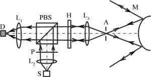
设计的收发隔离光学系统由发射和接收两路组成,其结构示意图如图 1所示。
该系统由探测器D、聚光镜L1、准直镜L2、扩束镜L3、偏振分束镜(polarization beam splitter, PBS)、起偏器P、信号发射源S、半波片H、光阑A、光学天线M等部分组成。信号发射源发出的光经过准直镜准直,再经过起偏器,变为偏振方向为y方向的线偏振光。偏振分束镜反射y反向偏振光,透射x方向偏振光。发射信号光通过偏振分束器反射后,再通过一个半波片,其中,半波片快轴方向与发射信号光偏振方向夹角为22.5°,最后经过准直镜和光学天线输出。接收信号依次通过光学天线、准直镜、半波片后透射过偏振分束镜,再经准直镜到达探测器。
-
设发射信号为单色非偏振光,其琼斯矩阵为[10]:E =[Ex Ey]。起偏器、偏振分束镜反射、透射,半波片正向入射、反向入射的琼斯矩阵分别为[10]:
$ \left\{ \begin{array}{l} {\mathit{\boldsymbol{J}}_{\rm{p}}} = \left[ {\begin{array}{*{20}{c}} 0&0\\ 0&1 \end{array}} \right]\\ {\mathit{\boldsymbol{J}}_{{\rm{PBS, r}}}} = \left[ {\begin{array}{*{20}{c}} 0&0\\ 0&1 \end{array}} \right]\\ {\mathit{\boldsymbol{J}}_{{\rm{PBS, t}}}} = \left[ {\begin{array}{*{20}{c}} 1&0\\ 0&0 \end{array}} \right]\\ {\mathit{\boldsymbol{J}}_{{\rm{h + }}}} = {\rm{i}}\left[ {\begin{array}{*{20}{c}} {1/\sqrt 2 }&{1/\sqrt 2 }\\ {1/\sqrt 2 }&{ - 1/\sqrt 2 } \end{array}} \right]\\ {\mathit{\boldsymbol{J}}_{{\rm{h}} - }} = {\rm{i}}\left[ {\begin{array}{*{20}{c}} {1/\sqrt 2 }&{ - 1/\sqrt 2 }\\ { - 1/\sqrt 2 }&{ - 1/\sqrt 2 } \end{array}} \right] \end{array} \right. $
(1) 发射光经过起偏器后可以被偏振分束镜反射,通过光学天线出射,不被探测器接收。同时,接收光信号到达探测器的光矢量可以表示为:
$ {\mathit{\boldsymbol{E}}_{\rm{r}}} = {\mathit{\boldsymbol{J}}_{{\rm{PBS, t}}}}{\mathit{\boldsymbol{J}}_{{\rm{h - }}}}{\mathit{\boldsymbol{J}}_{{\rm{h + }}}}{\mathit{\boldsymbol{J}}_{{\rm{PBS, r}}}}{\mathit{\boldsymbol{J}}_{\rm{p}}}\mathit{\boldsymbol{E}} = \left[ {\begin{array}{*{20}{c}} {{E_{\rm{y}}}}&0 \end{array}} \right] $
(2) 结果表明,接收信号光可以完全透过偏振分光片到达信号探测器,实现收发隔离。
由于偏振分束镜、半波片、扩束镜等表面存在的反射光有可能进入探测器,利用琼斯矩阵分析半波片及透镜的前后表面反射光。其中反射面和透镜的琼斯矩阵为[10]:
$ \left\{ \begin{array}{l} {\mathit{\boldsymbol{J}}_{\rm{r}}} = \left[ {\begin{array}{*{20}{c}} 1&0\\ 0&{ - 1} \end{array}} \right]\\ {\rm{ }}{\mathit{\boldsymbol{J}}_{{\rm{lens}}}} = \left[ {\begin{array}{*{20}{c}} 1&0\\ { - 1/f}&1 \end{array}} \right] \end{array} \right. $
(3) 式中, f为扩束镜焦距。则偏振分束镜后表面及半波片前表面的反射光到达探测器的琼斯矩阵为:E1=JPBS, tJrJPBS, rJpE=[0 0]。半波片后表面及扩束镜前表面反射光到达探测器的琼斯矩阵为:E2=JPBS, tJh-·JrJh+JPBS, rJpE=[0 0]。扩束镜后表面反射光到达探测器的琼斯矩阵为:E3=JPBS, tJh-JlensJrJlensJh+JPBS, r·JpE=[0 0]。由此可知,在理想的偏振分束情况下,偏振片及透镜前后表面反射光均不会进入信号探测器。扩束镜组其它镜片的反射光到达探测器的琼斯矩阵与第1片扩束镜后表面反射光到达探测器的琼斯矩阵一致,也不会进入信号探测器。但是由于发射光束偏振度、分束镜偏振性能及其造成的影响,难以实现绝对收发隔离。
-
假设在收发端调节半波片快轴与信号偏振方向的夹角误差为θ,则半波片正向入射、反向入射的琼斯矩阵分别为:
$ \left\{ \begin{array}{l} {J_{{\rm{h + }}}}\prime = {\rm{i}}\left[ {\begin{array}{*{20}{c}} {{\rm{cos}}\left( {\frac{{\rm{ \mathsf{ π} }}}{4} + 4\theta } \right)}&{{\rm{sin}}\left( {\frac{{\rm{ \mathsf{ π} }}}{4} + 4\theta } \right)}\\ {{\rm{sin}}\left( {\frac{{\rm{ \mathsf{ π} }}}{4} + 4\theta } \right)}&{ - {\rm{cos}}\left( {\frac{{\rm{ \mathsf{ π} }}}{4} + 4\theta } \right)} \end{array}} \right]\\ {J_{{\rm{h}} - }}\prime = {\rm{i}}\left[ {\begin{array}{*{20}{c}} {{\rm{cos}}\left( {\frac{{\rm{ \mathsf{ π} }}}{4} + 4\theta } \right)}&{ - {\rm{sin}}\left( {\frac{{\rm{ \mathsf{ π} }}}{4} + 4\theta } \right)}\\ { - {\rm{sin}}\left( {\frac{{\rm{ \mathsf{ π} }}}{4} + 4\theta } \right)}&{ - {\rm{cos}}\left( {\frac{{\rm{ \mathsf{ π} }}}{4} + 4\theta } \right)} \end{array}} \right] \end{array} \right. $
(4) 此时,信号探测器接收到的光矢量变为:Er′=JPBS, tJh-′Jh+′JPBS, rJpE=Ey[cos(4θ) 0]。若存在角度偏差时,偏振分束镜后表面及半波片前表面反射光到达探测器的琼斯矩阵为:E1′=JPBS, tJrJPBS, rJpE=[0 0]。半波片后表面及透镜前表面反射光到达探测器的琼斯矩阵可以表示为:E2′=JPBS, tJh-′JrJh+′·JPBS, rJpE=[0 0]。透镜后表面反射光到达探测器的琼斯矩阵可以表示为:E3′=JPBS, tJh-′JlensJrJlensJh+′·JPBS, rJpE=[0 0]。由此可知,半波片快轴与信号偏振方向夹角误差不会影响偏振片、透镜反射信号光到达信号探测器的光强,即收发隔离性能不会受到影响。
同时,存在调节误差与不存在调节误差时探测器接收光强不同,它们的比值为cos2(4θ)。由此可知,半波片快轴与信号偏振方向的夹角为22.5°时,探测器接收到的信号最强,当两者方向夹角偏离22.5°、并且偏离角为θ时,信号探测器接收到的光强按cos2(4θ)减小。因此,存在调节误差时会影响接收到的信号光光强,但是不会影响光学系统的偏振隔离度。
-
为了进一步提高系统隔离度,对偏振分束器的前表面进行楔角处理,由此可以达到更高的收发隔离度[11-12]。收发隔离度定义为在接收光敏面上,发射光功率中的后向反射、散射及光路系统后向散射光多次散射等后向接收光功率Pb和传输功率Pt的比值[3, 13-15],即:R=10lg(Pt/Pb)。为了得到系统收发隔离度,建立模型对所设计系统进行分析。
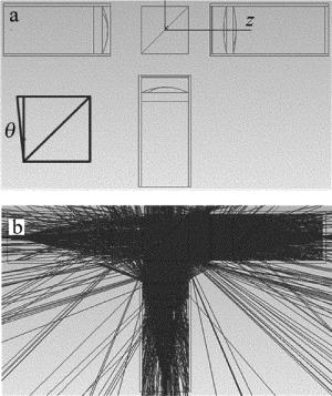
模拟光路模型如图 2a所示,信号发射光源波长采用1550nm,发射信号总功率为1W。图 2中各个元件表示意义与图 1相同,并假设各个透镜、起偏器、半波片透射率为99.5%,反射率为0.5%,直径为20mm。偏振分束镜对p光反射率为99.9%,透射率为0.1%,对s光透射率为99.9%,发射率为0.1%,镜筒为完美吸收体,探测器直径为100μm。图 2a中小图所示为偏振分束镜前表面的楔角θ。图 2b为系统模拟时的光路图。由于接收信号可以实现自动跟踪,在改变偏振分束镜角度的过程中可以保证接收信号光斑始终位于探测器中心,回波信号则会因为偏振分束镜角度的增大逐渐偏离探测器中心,从而在保证接收信号功率不变的同时增加系统收发隔离度。
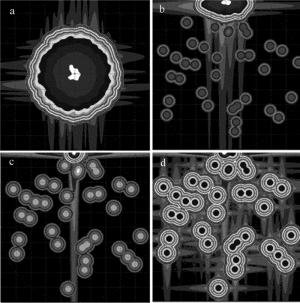
图 3所示为探测器上接收回波光强分布在不同参量,尤其在不同偏振分束镜楔楔角时的情况。图 3a中楔角为0mrad,接收光功率为1.8×10⁻⁵W,隔离度为47.3dB;图 3b中楔角为3.5mrad,接收光功率为3.01× 10⁻⁷W,隔离度为65.21dB;图 3c中楔角为3.98mrad,接收光功率为1.07× 10⁻⁹W,隔离度为89.70dB;图 3d中楔角为3.99mrad,接收光功率为5.06×10⁻¹³W,隔离度为122.96dB。本文中探测器的探测尺寸为0.1mm,因此它存在一定的视场范围,由于透镜前聚光镜的焦距为34.92mm,可得探测器全视场为:FFOV=arctan(0.1/34.92)=2.9mrad。随着楔角度的增加,探测器接收到的信号回波功率越来越小,偏振隔离度越来越大,在倾角大约为3.99mrad时超出探测器视场。可以看出, 在某一楔角度时,系统可以达到100dB的隔离度。对于不同的光学系统,该楔角与探测器光敏面尺寸及聚光镜的焦距有关。
在试验过程中, 由于遮光罩不可能完全遮挡所有外界杂散光,加上探测器自身噪声的影响、各种器件的制造公差影响,以及探测器的灵敏度影响等因素, 还不能达到如此高的隔离度,只有不断提升实验环境及器件来达到预期。
-
针对收发同轴光学系统设计了一种了偏振收发隔离光学系统。计算结果表明,该系统可以实现收发隔离,存在半波片角度误差时会降低接收的信号功率而不会影响收发隔离性能。系统偏振隔离度主要由偏振分束镜的消光比、反射面反射率以及偏振分束镜表面楔角决定。模拟探测器接收发射光回波功率随偏振分束镜楔角的变化,得出在消光比为1000: 1、反射面反射率为0.5%时,存在一定楔角,可以实现100dB的隔离度。对于高收发隔离度要求的系统,可以对偏振分束镜进行表面进行楔角处理来提高系统的收发隔离性能。
一种收发隔离光学系统的设计
Design of a transmitting-receiving isolation optical system
-
摘要: 为了实现高隔离度的收发隔离,采用一种偏振收发隔离光学系统,利用琼斯矩阵进行了理论分析,验证了偏振隔离在收发同轴光学系统中的可行性。采取空间隔离来抑制回波进入接收系统,研究了模拟系统中偏振分束镜前表面楔角大小对收发隔离度的影响。结果表明,在达到一定楔角时,可取得100dB收发隔离度。这一结果对收发同轴光学系统的设计具有一定指导意义。Abstract: In order to achieve high-degree isolation in a transceiver system, an isolation optical system was put forward based on polarization and analyzed by means of Jones matrix. The feasibility of polarization isolation in a coaxial optical transceiver was verified. The space separation was used to suppress the echo into the receiving system. The influence of the wedge angle of polarization beam splitter on transmitting-receiving isolation was studied. The results show that, the transmitting-receiving isolation of 100dB is achieved with a certain wedge angle. The results will be of guiding significance for the design of transmitting-receiving coaxial optical systems.
-
Key words:
- optical design /
- transmitting-receiving isolation /
- polarization beam splitter /
- isolation degree /
- echo
-
[1] YAN X B, YAN W P. Vertical multi-layer LED-induced fluorescence detection system[J]. Instrument Technique and Sensor, 2015(3):66-68(in Chinese). [2] WANG L, ZHAO H B, YU J Z, et al. Passive and active combined LADAR system design and simulation[J]. Infrared and Laser Engineering, 2015, 44(s1):68-72(in Chinese). [3] MANSOUR A, MESLEH R, ABAZA M. New challenges in wireless and free space optical communications[J]. Optics and Lasers in Engineering, 2017, 89:95-108. doi: 10.1016/j.optlaseng.2016.03.027 [4] LÜ J, MA X L, HE Y H, et al. Simulation test and inhibit method of forward scattered stray light of polarized beam split optical antenna[J]. Acta Photonica Sinica, 2015, 45(4):406002(in Chinese). [5] GAO P, HU Y H, ZHAO N X, et al. Laser ranging precision in sending and receiving coaxial optical system in indoor instance[J]. Infrared and Laser Engineering, 2014, 43(3):915-919(in Chinese). [6] TAO H R, ZHANG F M, QU X H. Experimental study of backscattering signals from rough targets in non-cooperative laser measurement system[J]. Infrared and Laser Engineering, 2014, 43(s1):95-100(in Chinese). [7] CHEN H Y, HAN Y B. Overview of free space optical communication technology[J]. Guangxi Communication Technology, 2010(1):39-42(in Chinese). [8] SONG Y L, NI R G. Research into transmitter-receiver isolation technique of radar countermeasure system[J]. Shipboard Electronic Countermeasure, 2012, 35(1):20-24(in Chinese). [9] WANG J M, WU F Q, KONG W J, et al. Analysis of isolation performance of wave type optical isolator[J]. Acta Photonica Sinica, 2004, 33(7):830-834(in Chinese). [10] YAN J X, WEI G H, HA L Z. Matrix optics[M]. Beijing:Ordnance Industry Press, 1995:51-100(in Chinese). [11] YE D M, XIE L M, CHEN J. Ground simulation analysis of satellite-ground optical communication based on tracking error compensation[J]. Laser Technology, 2012, 36(3):346-348(in Chinese). [12] LIU B, WANG J Sh, YANG Z H, et al. Study on non-line-of-sight infrared laser scattering communication in atmosphere[J]. Laser Technology, 2014, 38(6):854-858(in Chinese). [13] WANG B, FEI J Ch, CUI Zh F, et al. Research of degree of polarization of PCELG beam progagation through a circular aperture[J]. Laser Technology, 2013, 37(5):672-678(in Chinese). [14] YANG J, WANG H, ZHANG X. Influence of atmospheric turbulence on Rayleigh range of partially coherent laser[J]. Laser Technology, 2016, 40(3):456-460(in Chinese). [15] YAO M, ZHANG L, XU C W, et al. Modeling and simulation of slant path scattering of 1.064μm laser in atmosphere[J]. Laser Technology, 2012, 36(3):394-397(in Chinese). -


 网站地图
网站地图


 下载:
下载:


