 网站地图
网站地图


-
近年来,光纤激光器由于具有小抽运阈值、高传输光束质量、高波长灵活性、小体积等优势和特点[1-2],尤其是单波长、高单色性的光纤激光器,在光纤传感、光通信、激光切割、光谱测量等领域得到广泛研究与应用[3-4]。当前,主要通过控制光纤激光器谐振腔的长度[5-6]或在腔内引入窄带光纤滤波器[7-8]来实现光纤激光器的窄带选模输出。光纤谐振腔主要分为线性和环形两种类型[9],线性谐振腔光纤激光器通常采用在增益光纤上引入光栅或者采用将二者对接等方式构成短直腔[10-12],增大输出纵模之间的间隔以实现单模输出,但是具有成本高、封装技术复杂等不足; 环形谐振腔激光器由于腔长较长,导致输出模式较多,需要加入如光纤光栅[13-14]、饱和吸收体[15-16]、级联法布里-珀罗(Fabry-Perot, F-P)腔[17-18]、有源注入复合腔[9, 19]等光纤滤波器件以实现单波长输出。2015年,YEH等人将光纤布喇格光栅作为光纤滤波器置于环形腔中,实现了线宽小于0.02 nm的单波长输出[13]。2020年,WAN等人提出了一种基于Er3+、Yb3+掺杂增益光纤花生结结构的光纤滤波器,实现了线宽小于0.02 nm的窄线宽单波长激光输出[20]。2022年,GAO等人提出一种基于保偏光纤布喇格F-P腔的滤波器,实现了稳定的双波长输出[18]。
然而,光纤光栅、F-P腔等窄带滤波器在制备工艺和封装方式等方面有较高的要求。因此,提高系统紧凑性和性价比的同时还要使激光输出带宽减小且能保证系统具有较高的稳定性, 成为当前单波长光纤激光器的研究重点。本文作者提出一种基于单模石英-掺铒-单模石英结构混合介质光纤干涉仪(hybrid fiber interfero-meter, HFI)的单波长光纤激光器。基于熔融错位熔接法制备获得全光纤结构HFI,通过控制中间段有源铒掺杂光纤(erbium-doped fiber, EDF)的长度和错位量优化HFI光谱特性。搭建全光纤环形激光器实验系统,基于HFI中间段EDF的饱和吸收效应以及HFI的窄带光谱进行腔内选模,实现单波长、稳定的窄带激光输出。该激光器结构紧凑、稳定性和单色性好,在光纤传感和相干通信系统等领域具有实际应用价值。
-
HFI结构如图 1所示。图中,d为第1段无源单模光纤(single-mode fiber, SMF)与EDF的光纤错位量,L为中间段EDF长度。入射光从SMF1左端(8 μm/125 μm)进入,光场沿着光纤纤芯(LP01模式)传输至中间段有源EDF光纤(5.5 μm/125 μm)处。LP(line-ar polarization)表示线偏振。光传输到SMF1和EDF交界面处,由于纤芯失配而激发包层模(LP1m模式),部分光场进入包层传播从而形成包层模,另一部分则继续在纤芯中传输。在SMF1和EDF接触处引入适当的错位量d,激发更多的包层模与纤芯模产生模式干涉。由于纤芯与包层具有不同的折射率,光在EDF中传输一段距离之后,纤芯模与包层模之间会产生一定的相位差。当光传播到EDF和第2段单模光纤SMF2(8.2 μm/125 μm)交界面处,包层模和纤芯模将汇聚并同时进入SMF2中进行传输,从而形成模间干涉[10]。
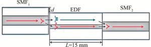
图 1 混合介质光纤干涉仪结构及光场模式传输示意图
Figure 1. Schematic diagram of mixed medium optical fiber interferometer structure and optical field mode transmission
根据光场干涉叠加原理,干涉光谱强度为[20]:
$ I=I_{\text {core }}+I_{\text {clad }}+2 \sqrt{I_{\text {core }} I_{\text {clad }}} \cos (2 {\rm{\mathsf{π}}} \delta / \lambda+\Delta \phi) $
(1) 式中,λ为入射光波长,Icore和Iclad分别为LP01模式和LP1m模式的传输光强度,δ为LP01模式和LP1m模式的光程差,Δϕ为初始的相位差,这里认为Δϕ=0,Δφ是LP01模式和LP1m模式之间的相位差,可表示为:
$ \Delta \varphi=\frac{2 {\rm{\mathsf{π}}} \delta}{\lambda}+\Delta \phi=\frac{2 {\rm{\mathsf{π}}} \Delta n_{\text {eff }} L_{\text {eff }}}{\lambda} $
(2) 式中,Δneff是光纤纤芯和包层两种传输介质的有效折射率差,Leff为有效干涉长度,此处等于中间段错位光纤的长度L。干涉的极大值即为干涉谱的峰值处,干涉的极小值即为干涉谱的谷底处。
当LP01模式和LP1m模式的相位差为π的奇数倍(2N+1)时,即Δφ=2πΔneffLeff/λ=(2N+1)π,有cos(2πδ/λ+Δϕ)=-1,I取最小值Imin,干涉相消,对应的干涉波谷中心波长λmin可表示为:
$ I_{\min }=I_{\text {core }}+I_{\text {clad }}-2 \sqrt{I_{\text {core }} I_{\text {clad }}} $
(3) $ \lambda_{\text {min }}=2 \Delta n_{\text {eff }} L_{\text {eff }} /(2 N+1) $
(4) 当LP01模式和LP1m模式的相位差为π的偶数倍2N时,即Δφ=2πΔneffLeff/λ=2Nπ,有cos(2πδ/λ+Δϕ)=1,I取最大值Imax,干涉相长,对应的干涉波峰中心波长λmax可表示为:
$ I_{\max }= I_{\text {core }}+I_{\text {clad }}-2 \sqrt{I_{\text {core }} I_{\text {clad }}} $
(5) $ \lambda_{\text {max }}=\Delta n_{\text {eff }} L_{\text {eff }} / N $
(6) 由此可以得出两个相邻波谷(波峰)之间的波长差为:
$ \Delta \lambda=\lambda^2 /\left(2 \Delta n_{\text {eff }} L_{\text {eff }}\right) $
(7) 相邻两个波峰(波谷)的波长间距为自由光谱范围(free spectral range, FSR)RFSR由干涉区域的长度Leff来控制,当EDF长度越长,RFSR越小,可表示为:
$ R_{\mathrm{FSR}}=\lambda^2 / \delta $
(8) $ \delta=2 \Delta n_{\text {eff }} L_{\text {eff }} $
(9) 干涉光谱的消光比Re可表示为:
$ R_{\mathrm{e}}=\frac{2 \sqrt{I_{\text {core }} I_{\text {clad }}}}{1+I_{\text {core }} / I_{\text {clad }}} $
(10) 由(10)式可知,Re的大小主要由干涉光的光强决定,当通过LP01模式和LP1m模式的光强相等时,干涉光谱的Re最高。利用相关软件仿真计算得到模式干涉光谱的归一化谱线, 如图 2所示。图 2a为EDF长度(L=15 mm)固定不变,改变错位量(d变化范围为0 μm~16 μm)得到的HFI干涉光谱变化规律; 图 2b为错位量固定不变(d=14 μm),改变中间段EDF长度(L变化范围为10 mm~25 mm)得到的HFI干涉光谱变化规律。由图 2a可知,当L=15 mm时,存在最佳错位量(d=14 μm),干涉光谱Re最大可达34 dB;由图 2b可知,当d=14 μm时,干涉光谱的RFSR随着L的增加而变小,与(8)式相一致。
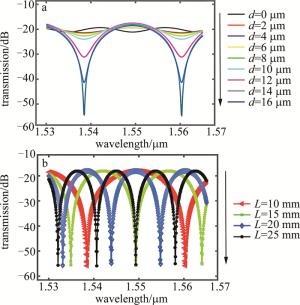
图 2 不同d和L下仿真计算得到的HFI干涉光谱
Figure 2. HFI interference spectra obtained by simulation calculation under different d and L
-
预制棒为Er3+、Al3+离子掺杂SiO2玻璃材料,经过高温熔缩、沉积纤芯,再浸泡于Er3+、Al3+离子溶液等流程制备。通过拉丝装置[21]将EDF预制棒拉制成光纤,具体过程为:首先将预制棒放置在送棒装置上,置于加热炉口中心处且垂直于地面,加热炉中的电阻丝被用来加热预制棒;然后通过拉丝塔控制台和热电偶将温度范围升高至1900 ℃~2000 ℃,步长为20 ℃~30 ℃,保温10 min使拉丝温度稳定;最后调整送棒速率和最大送棒长度的同时控制拉丝滚轮转速调整拉丝速率(1.5 m/min~20 m/min)以保证制备光纤的直径大小,得到的EDF光包层约125 μm, 模场直径在1550 nm时为5 μm~6 μm,抽运功率吸收系数在980 nm时大于3 dB/m,在1530 nm时为5 dB/m~7 dB/m。
-
图 3为使用错位熔接法制备的HFI中间段EDF与SMF1的实物照片图。中间段EDF长度为15 mm, 两端无源SMF长度之和小于50 cm; 光纤对准错位d变化范围为0 μ~10 μm,错位控制精度为0.1 μm。图 3a展示了用于控制两端光纤之间的错位量的程序;改变错位量之后两光纤位置如图 3b所示;通过放电将两端光纤错位熔接,熔接后的图片即为图 3c。为研究并获得最佳HFI光谱,向SMF1通入宽带光源,改变d以及中间段EDF的长度,通过光谱仪(optical spectrum analyser, OSA)实时观察干涉仪光谱的变化情况。
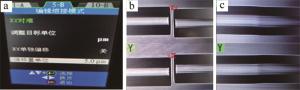
图 3 a—用于控制光纤错位量程序图b—光纤错位图c—错位熔接后的实物图照片
Figure 3. a—program diagram for controlling optical fiber misalignment b—optical fiber dislocation diagram c—picture of the real object after dislocation welding
图 4为L=15 mm、不同错位量d时测得的HFI干涉光谱变化规律。

图 4 L=15 mm、不同错位量d时的HFI干涉光谱图
Figure 4. HFI interference spectrum measured experimentally with L=15 mm and different dislocation d
表 1中列出了在L=15 mm时、不同错位量d时的RFSR和Re实验数值特性。实验测试结果表明,干涉光谱的RFSR随着错位量d的增加而减小,损耗随着错位量d的增加而增加。可以看出存在一个最佳值,当d=14 mm时,使得干涉光谱Re最大可达34.66 dB。实验变化规律与上述理论仿真结果相一致。
表 1 L=15 mm、不同错位量d时的RFSR和Re
Table 1. RFSR and Re under different dislocation d obtained with L=15 mm
d/μm Re/dB RFSR/nm loss/dB 0~6 — — — 7 3.3 16.23 -12.36~-9.03 8 4.3 16.5 -15.41~-11.13 9 5.4 16.23 -18.66~-13.23 10 6.6 16.23 -21.98~-15.43 11 7.7 16.1 -24.82~-17.12 12 14 16.91 -33.99~-19.95 13 27.5 14.81 -49.81~-22.28 14 34.66 14.84 -62.11~-27.45 15 26.9 14.6 -55.64~-28.75 16 21.8 14 -52.04~-30.26 当L=20 mm、错位量d变化范围为10 μm~16 μm时, 对应的HFI干涉光谱实验测试结果如图 5所示。可以看出, 当d=13 μm时,Re最大为24.35 dB。与L=15 mm相比较,L=20 mm时损耗更高,RFSR和Re都更低, 即当EDF的长度较长时,HFI的光场传输损耗更高。
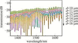
图 5 L=20 mm、不同错位量d时的HFI干涉光谱图
Figure 5. HFI interference spectrum measured experimentally with L=20 mm and different dislocation d
当L分别为7 mm和10 mm时,实验测得的干涉光谱分别如图 6a和图 6b所示。当L < 15 mm时, HFI的损耗降低,但是获得的Re最大值(30.02 dB)小于L=15 mm时的Re最大值(34.66 dB),并且可以看出, RFSR随着L的减小而增加,与上述理论仿真结果相一致。
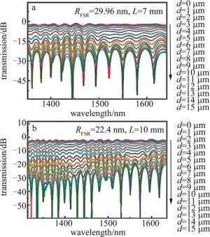
图 6 当L=7 mm和L=10 mm时, 实验测得的干涉光谱图
Figure 6. Interference spectrum of experimental test results when L=7 mm and L=10 mm
当d=12 μm时,EDF长度L变化规律如图 7所示。实验测试结果表明,干涉光谱的Re随着L的增加呈现出先增加再减小的趋势,当L=15 mm时达到最大,处于最佳。
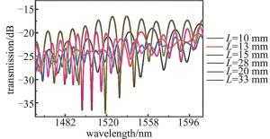
图 7 d=12 μm、L不同时的HFI干涉光谱图
Figure 7. HFI interference spectrum with different L and d=12 μm
-
图 8为基于HFI的单波长光纤激光器实验系统结构示意图。该激光器具有全光纤、环形腔结构。980 nm抽运激光(输出功率0 mW~200 mW)经过一个980 nm/1550 nm波分复用器(wavelength division multiplexing, WDM)注入一段长度为3 m的EDF,然后相继通过一个偏振相关光纤隔离器(polarization dependent isolator, PDI)和偏振控制器(polarization controller, PC), PDI用于控制激光腔内光的单向传输,防止光在光纤传播过程中的后向散射干扰系统, PC用于控制光场偏振状态;最后通过一个90 ∶10光纤耦合器将光反馈输入环形腔内和激光功率输出到OSA。通过HFI结构的选模作用以及EDF的饱和吸收效应实现稳定的单波长窄带激光输出。
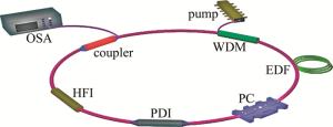
图 8 光纤激光器结构示意图
Figure 8. Structure diagram of fiber laser
结合仿真结果以及HFI光谱变化趋势,为了获得最佳选模效果,选择L=15 mm的HFI作为环形光纤激光器腔内选模器件。整个光纤激光器实验系统置于气浮式光学平台上以增加激光器系统的稳定性。图 9为激光3 dB线宽小于0.02 nm、L=15 mm和不同d时, 实验测得的单波长光纤激光器光谱测试结果。图中小插图为激光光谱放大视图。可以看出,当d=7.9 μm(见图 9a)时获得单波长激光输出光谱最高信噪比(signal-to-noise ratio, SNR)为38 dB; 当d>8.1 μm时,错位熔接带来的损耗将大大降低激光器的输出效率。图 10为L=15 mm和d=7.9 μm时,输出功率和抽运功率的关系。此时激光功率阈值为50 mW。
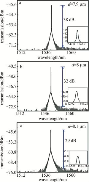
图 9 当L=15 mm和不同d时的单波长激光
Figure 9. Single wavelength laser when L=15 mm and different displacement d
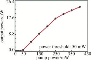
图 10 当L=15 mm和d=7.9 μm时,输出功率和抽运功率的关系
Figure 10. Relationship between output power and pump power when L=15 mm and d=7.9 μm
图 11为实验测得的激光器输出稳定性测试结果。将整个光纤激光器实验系统置于恒温和隔振光学平台上, 向光纤环腔内引入HFI(d=7.9 μm,L=15 mm)后,将带宽压缩,滤除了多余的激光模式,中间段EDF饱和吸收效应有利于进一步抑制跳模,实现单波长激光输出。由于增益光纤长度较短,获得的激光发射波长位于光通信C波段1545 nm附近, 单波长激光输出光谱较为稳定。

图 11 单波长光纤激光器2 h输出稳定性测试结果
Figure 11. Test results of 2 h output stability of single wavelength fiber laser
-
提出了一种基于HFI的单波长光纤激光器。利用熔融错位熔接法制备了SMF-EDF-SMF结构的HFI。理论仿真计算了HFI干涉光谱随错位量d和EDF长度L的变化规律。实验结果和理论结果一致:当EDF长度L=15 mm、最佳错位量d=14 μm时,HFI内光场干涉谱Re最大为34.66 dB。选择中间段EDF长度为15 mm的HFI作为环形光纤激光器的单波长全光纤选模器件,搭建了光纤激光器实验系统,当d达到7 μm~ 8 μm左右,基于HFI的窄带选模特性以及中间段EDF的饱和吸收效应实验获得了具有较高稳定性的单波长光纤激光器输出。该激光器在光纤传感和光纤通信系统具有潜在的应用价值。
基于混合介质光纤干涉仪的单波长光纤激光器
Single wavelength fiber laser based on hybrid fiber interferometer
-
摘要: 为了实现单波长输出, 提出了一种基于单模石英-掺铒-单模石英结构混合介质光纤干涉仪(HFI)的单波长光纤激光器。基于混合介质光纤波导内的光场干涉原理及光波导理论, 分析了HFI的模式干涉理论, 研究了HFI内干涉光特性随中间段铒掺杂光纤(EDF)长度以及错位量的变化规律; 采用熔融错位法制备HFI, 优化了EDF的长度和单模光纤与EDF之间的偏移量。结果表明, 最佳EDF长度为15 mm, 单模光纤与EDF之间的最佳偏移量为7.9 μm; 选择长度为15 mm的EDF HFI作为环形光纤激光器谐振腔的选模器件, 可获得较高稳定性的单波长光纤激光器输出。这一结果对该激光器在光纤传感和光纤通信系统的应用是有帮助的。Abstract: To achieve single wavelength output, a single wavelength fiber laser based on a single-mode quartz-erbium-doped single-mode quartz hybrid fiber interferometer (HFI) was proposed. Based on the optical field interference principle and optical waveguide theory in hybrid dielectric fiber waveguides, the mode interference theory of HFI was analyzed, and the variation of the interference optical characteristics in HFI with the length and dislocation amount of the intermediate erbium-doped fiber (EDF) was studied. HFI was prepared using a melt dislocation method, which optimized the length of the EDF and the offset between the single-mode fiber and the EDF. The results show that, the optimal EDF length is 15 mm, and the optimal offset between the single-mode fiber and the EDF is 7.9 μm. Selecting an EDF HFI with a length of 15 mm as a mode selector for the resonator of a ring fiber laser can achieve a relatively stable single wavelength fiber laser output. This result is helpful for the application of the laser in optical fiber sensing and communication systems.
-
图 1 混合介质光纤干涉仪结构及光场模式传输示意图
Figure 1. Schematic diagram of mixed medium optical fiber interferometer structure and optical field mode transmission
图 2 不同d和L下仿真计算得到的HFI干涉光谱
Figure 2. HFI interference spectra obtained by simulation calculation under different d and L
图 3 a—用于控制光纤错位量程序图b—光纤错位图c—错位熔接后的实物图照片
Figure 3. a—program diagram for controlling optical fiber misalignment b—optical fiber dislocation diagram c—picture of the real object after dislocation welding
图 4 L=15 mm、不同错位量d时的HFI干涉光谱图
Figure 4. HFI interference spectrum measured experimentally with L=15 mm and different dislocation d
图 5 L=20 mm、不同错位量d时的HFI干涉光谱图
Figure 5. HFI interference spectrum measured experimentally with L=20 mm and different dislocation d
图 6 当L=7 mm和L=10 mm时, 实验测得的干涉光谱图
Figure 6. Interference spectrum of experimental test results when L=7 mm and L=10 mm
图 7 d=12 μm、L不同时的HFI干涉光谱图
Figure 7. HFI interference spectrum with different L and d=12 μm
图 9 当L=15 mm和不同d时的单波长激光
Figure 9. Single wavelength laser when L=15 mm and different displacement d
图 10 当L=15 mm和d=7.9 μm时,输出功率和抽运功率的关系
Figure 10. Relationship between output power and pump power when L=15 mm and d=7.9 μm
图 11 单波长光纤激光器2 h输出稳定性测试结果
Figure 11. Test results of 2 h output stability of single wavelength fiber laser
表 1 L=15 mm、不同错位量d时的RFSR和Re
Table 1. RFSR and Re under different dislocation d obtained with L=15 mm
d/μm Re/dB RFSR/nm loss/dB 0~6 — — — 7 3.3 16.23 -12.36~-9.03 8 4.3 16.5 -15.41~-11.13 9 5.4 16.23 -18.66~-13.23 10 6.6 16.23 -21.98~-15.43 11 7.7 16.1 -24.82~-17.12 12 14 16.91 -33.99~-19.95 13 27.5 14.81 -49.81~-22.28 14 34.66 14.84 -62.11~-27.45 15 26.9 14.6 -55.64~-28.75 16 21.8 14 -52.04~-30.26  下载: 导出CSV
-
[1] 陈龙辉, 谢芳, 郭晓蕾, 等. 可调谐单纵模多波长光纤激光器的研究[J]. 激光技术, 2021, 45(6): 681-685. CHEN L H, XIE F, GUO X L, et al. Study on tunable single longitudinal mode multiwavelength fiber laser[J]. Laser Technology, 2021, 45(6): 681-685(in Chinese). [2] YU L Q, LU D, PAN B W, et al. Widely tunable narrow-linewidth lasers using self-injection DBR lasers[J]. IEEE Photonics Technology Letters, 2015, 27(1): 50-53. doi: 10.1109/LPT.2014.2361833 [3] 朱志坚, 薛竣文, 王玉珂, 等. 基于MOPA结构的1064 nm单频光纤激光器[J]. 激光技术, 2019, 43(6): 800-803. ZHU Zh J, XUE J W, WANG Y K, et al. 1064 nm single frequency fiber laser based on MOPA structure[J]. Laser Technology, 2019, 43(6): 800-803(in Chinese). [4] 王婉琳, 王蓟, 徐廉伟, 等. 基于半导体可饱和吸收镜的可调谐光纤激光器[J]. 激光技术, 2019, 43(5): 672-675. WANG W L, WANG J, XU L W, et al. Tunable fiber laser with semiconductor saturable absorption mirror[J]. Laser Technology, 2019, 43(5): 672-675(in Chinese). [5] ZHANG Y N, LI C, XU Sh H, et al. A broad continuous temperature tunable DBR single-frequency fiber laser at 1064 nm[J]. IEEE Photonics Journal, 2016, 8(2): 1-7. [6] HUANG Zh P, DENG H Q, YANG Ch Sh, et al. Self-injection locked and semiconductor amplified ultrashort cavity single-frequency Yb3+-doped phosphate fiber laser at 978 nm[J]. Optics Express, 2017, 25(2): 1535-1541. doi: 10.1364/OE.25.001535 [7] 魏兴春, 欧攀, 张春熹, 等. 单频单偏振窄线宽光纤激光器及其放大研究[J]. 激光技术, 2010, 34(1): 5-7. WEI X Ch, OU P, ZHANG Ch X, et al. Study on single frequency single polarization narrow linewidth fiber laser and its amplification[J]. Laser Technology, 2010, 34(1): 5-7(in Chinese). [8] XU X, YOU Y J, HOU J X, et al. Ultra-narrow bandwidth and large tuning range single-passband microwave photonic filter based on bri-llouin fiber laser[J]. Optics & Laser Technology, 2022, 157: 108735. [9] WAN H D, WU Zh W, LU Zh M, et al. A watts-level single-longitudinal-mode kHz-linewidth fiber laser based on a gain-controlled active compound cavity[J]. Laser Physics, 2014, 24(10): 105114. doi: 10.1088/1054-660X/24/10/105114 [10] GAO Y, SUN J Q, CHEN G D, et al. Single-longitudinal-mode BEFL incorporating a Bragg grating written in EDF[J]. Optics Communications, 2015, 345: 125-128. doi: 10.1016/j.optcom.2015.02.007 [11] YIN B, LIU Zh B, FENG S Ch, et al. Stable single-polarization single-longitudinal-mode linear cavity erbium-doped fiber laser based on structured chirped fiber Bragg grating[J]. Applied Optics, 2015, 54(1): 6-11. doi: 10.1364/AO.54.000006 [12] RAZAK N F, AHMAD H, ZULKIFLI M Z, et al. Single mode EDF fiber laser using an ultra-narrow bandwidth tunable optical filter[J]. Optik—International Journal for Light and Electron Optics, 2015, 126(2): 179-183. doi: 10.1016/j.ijleo.2014.08.150 [13] YEH Ch H, CHEN H Zh, CHEN J Y, et al. Use of fiber Bragg grating(FBG) for stable and tunable erbium-doped fiber ring laser with single-longitudinal-mode(SLM) output[J]. Laser Physics, 2015, 25(11): 115101. doi: 10.1088/1054-660X/25/11/115101 [14] WAN H D, LI H Y, WANG Ch L, et al. An injection-locked, single-longitudinal-mode fiber ring laser with cylindrical vector beam emission[J]. IEEE Photonics Journal, 2017, 9(1): 7100608. [15] CHEN J W, ZHAO Y, ZHU Y N, et al. Narrow line-width ytterbium-doped fiber ring laser based on saturated absorber[J]. IEEE Photonics Technology Letters, 2017, 29(5): 439-441. [16] 杨敬, 瞿荣辉, 孙国勇, 等. 一种新型结构的单纵模光纤激光器[J]. 中国激光, 2005, 32(4): 441-444. YANG J, QU R H, SUN G Y, et al. A novel single longitudinal mode fiber laser[J]. Chinese Journal of Lasers, 2005, 32(4): 441-444(in Chinese). [17] WAN H D, JIANG W F, GONG Y, et al. Single-longitudinal-mode fiber ring laser stabilized by tandem all-fiber Fabry-Pérot micro-cavities[J]. IEEE Photonics Technology Letters, 2012, 24(5): 404-406. [18] GAO M Q, YIN B, LV Y Zh, et al. Tunable and switchable dual-wavelength SLM narrow-linewidth fiber laser with a PMFBG-FP filter cascaded by multi-ring cavity[J]. Photonics, 2022, 9(10): 9100756. [19] 刘天山, 任浩, 赵玺蛟, 等. 级联复合腔对光纤激光模式的抑制影响[J]. 半导体光电, 2010, 31(2): 199-201. LIU T Sh, REN H, ZHAO X J, et al. Suppression effect of cascaded composite cavities on fiber laser modes[J]. Semiconductor Optoelectronics, 2010, 31(2): 199-201(in Chinese). [20] WAN H D, CHEN Y F, ZHOU Q, et al. Tunable, single-wavelength fiber ring lasers based on rare earth-doped, double-peanut fiber interferometers[J]. Journal of Lightwave Technology, 2019, 38(6): 1501-1505. [21] 陈彧芳, 沈骁, 万洪丹, 等. 基于磷酸盐玻璃微球腔的全光调谐光纤滤波器[J]. 中国激光, 2021, 48(1): 0106003. CHEN Y F, SHEN X, WAN H D, et al. All-optical tunable fiber filter based on phosphate glass microsphere cavity[J]. Chinese Journal of Lasers, 2021, 48(1): 0106003(in Chinese). -

 点击查看大图

计量
- 文章访问数: 3732
- HTML全文浏览量: 2805
- PDF下载量: 19
- 被引次数: 0
