 网站地图
网站地图


-
激光凭借着方向性好、亮度高、单色性好、相干性高等特点,在加工领域有着广泛的应用,包括激光切割、激光打孔、激光焊接、激光标刻等[1-3]。激光振镜加工利用高能量密度激光束与材料的作用,结合高速转动的振镜[4]进行光束路径进行规划,极大提高打标速度和定位精度,成为激光打标、激光内雕、激光打孔等主要技术手段。
激光振镜加工输入图形可为位图或矢量图,位图一般通过二值化[5]后,根据像素值0或1,进行点阵扫描;矢量图则是通过路径信息,输出图像的轮廓,具有更高的分辨率和无放大失真等特点[6]。PLT文件[7]是激光矢量加工中常用的交互图形文件,由于其结构简洁,处理效率高,被广泛运用于激光振镜加工领域中。但另一方面,由于数据全为线段点集,只能根据标刻幅面进行等比例放大取整,输出缺少灵活性: 当放大比例较小时,高密集数据点集的标刻步距很小甚至为0,数据点过多上位机数据发送速率与振镜速率不匹配,激光在某一点停滞时间过长,导致激光烧蚀[8];放大比例较大时,相应的标刻步距变大,稀疏数据点集线段化明显,标刻精度和质量降低。贝塞尔曲线作为计算机图形学中常用参量曲线,通过改变参量t增量控制标刻步距大小,可适应各种标刻放大比例,具有更高的标刻精度和质量[9], 并且存储形式为贝塞尔曲线的文件具有数据量更小、放缩不变等优点。所以将线段点集拟合成少量控制点的贝塞尔曲线可解决加工PLT文件中点集分布过于密集或稀疏的问题。
点集拟合成B样条[10]或非均匀有理B样条曲线(non-uniform rational B-splines, NURBS)[11],最常用的方法是渐进迭代逼近法(progressive iterative approximation, PIA)[12],在点集中根据曲率大小选取主特征点,将其作为控制点并根据生成的曲线与点集误差进行控制点迭代,最终达到误差要求。但PIA迭代计算量大,当拟合误差要求较小时,迭代次数大,添加的控制点多,后面由曲线计算标刻路径更加复杂,并且矢量文件中曲线类型多为3阶贝塞尔曲线,表达更加简易。Potrace算法[13-14]可以将位图经过二值化、轮廓提取[15]、最优多边形和光滑处理,转换成只有直线和3阶贝塞尔曲线的矢量图,可用来消除放大位图带来的锯齿效应,但其不适用点集拟合曲线,具有较大拟合误差。因此,为了解决密集点集在激光振镜加工中由于放大比例差异引起的激光烧蚀及锯齿化问题,作者设计出三角二分法用于点集的曲线拟合,将点集转成由直线和贝塞尔曲线组成的控制点集,再根据标刻放大比例进行统一的步距规划,减少数据量的同时保证标刻的精度和质量。
-
如图 2所示,为初始点集,分布密集且不均匀,短线段可以合并成更长的线段。首先使用尽可能少的直线来替代直线点集,再在简化点集中找到曲线点集。
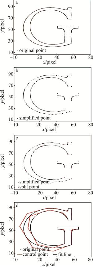
Figure 2. The process of point set fitting
-
在保证转换精度前提下,尽可能将点集使用更少的直线替代。如图 3所示,现假设直线P1Qi-1在满足转换精度条件下可替代P1和Qi-1之间所有的点,下一点为P2,分析直线P1P2是否可以替代P1Qi-1。首先直线P1P2表达式为:
$ \left\{\begin{array}{l} A x+B y+C=0 \\ A=y_{P_{2}}-y_{P_{1}} \\ B=x_{P_{1}}-x_{P_{2}} \\ C=x_{P_{2}} y_{P_{1}}-x_{P_{1}} y_{P_{2}} \end{array}\right. $
(1) 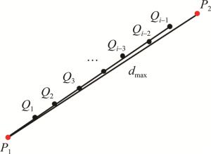
Figure 3. Line thinning
依次计算P1和P2之间的点Qi到直线P1P2的距离d:
$ d=\frac{\left|A x_{Q_{i}}+B y_{Q_{i}}\right|}{\sqrt{A^{2}+B^{2}}} $
(2) Qj(1≤j≤i-1)到P1P2的最大距离dmax即该点集用直线拟合的最大误差,假设直线拟合的允许误差为εline, 分为两种情况:当最大误差小于εline时,点集P1~P2间的点可用直线P1P2代替,取P2后一点作为新的P2,重复以上流程;当误差大于εline时,P2无法与前面点集共直线,P1Qi-1为满足误差的最长拟合直线,可将P1Qi-1的点全部去除,并将点Qi-1和P2作为下一点集,取P2后一点作为P2,Qi-1则作为点集起始点P1重复以上流程。
如图 2b所示,εline=0.02pixel,通过将每一个封闭点集进行直线稀疏化,减少了直线点集中间的点及一些曲线点集相离很近且接近于直线的点,便于后面对直线进行统一的步距规划。
-
便于后续的求解,选用3阶贝塞尔曲线,有4个控制点,所以对于拟合的点集来说,点个数不小于4才能对点集简化。如图 4a所示, 假设点P0, P1, P2属于曲线点集,判断P3是否属于曲线点集。由向量公式:
$ \cos \beta=\frac{\overrightarrow{P_{1} P_{2}} \overrightarrow{P_{2} P_{3}}}{\left|\overrightarrow{P_{1} P_{2}}\right|\left|\overrightarrow{P_{2} P_{3}}\right|} $
(3) 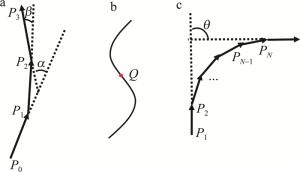
Figure 4. Curve point set criterion and segmentation
式中,β为曲线当前点切向方向和前一点切向方向的夹角。连续曲线点集向量夹角变化很小,所以这里满足曲线判据初始要求为cosβ>0.95,保证曲线切向改变的连续性。另要排除一些极端情况:比如3点满足 $|\overrightarrow{P_{2} P_{3}}|>3| \overrightarrow{P_{1} P_{2}} \mid, P_{2} P_{3} $ 是一条稀疏后的直线,P3不属于曲线点集;如图 4b中Q点所示,曲线的3阶拐点也作为曲线分段的标志点,和(3)式相同,求出cosα(α为曲线当前点切向方向和前两点切向方向的夹角),保证cosα>cosβ, 若不满足,说明曲率方向改变,将曲线以该点一分为二。若P3属于曲线集,取P3下一点作为新的点P3继续对下一点判据; 若P3不属于曲线集,则判断当前曲线集点的个数是否不小于4,满足则作为一组曲线点集,否则该点集作为常规线段点集。
为了便于控制曲线形状,将连续的曲线点集进行分段,保证每一段的拐角都小于90°,首尾控制点切线连线可构成三角形包裹整个曲线点集,如图 4c所示, P1作为起始点,PN作为终点,两点切向向量夹角θ<π/2,两点间点集作为贝塞尔曲线拟合的基本单位,再将PN作为起点,寻找下一终点。连续曲线点集的最终剩下的若干点,若点个数小于4,则直接归于前一段点集,否则作为新的一段。如图 2c所示, 红色点为分段曲线分界点,可看出每段曲线点集角度偏转不超过90°。
-
由于前面的曲线点集的分段保证了首尾点的夹角不会超过90°,且贝塞尔曲线的首尾控制点正好为曲线上的点,折线与曲线相切。根据这一特性,通过求取估算点集两端切线,两切线相较于点Q,B1和BN即为控制点P0和P3, 且P1和P2分别位于切线B1Q和BNQ上,所以如何调整P1和P2的位置得到的拟合曲线与点集间的误差最小,算法流程见下。
(1) 如图 5a所示, 需要对点集进行拟合,求出首尾端点的切线相交于Q点, $ t=\frac{\left|\overrightarrow{P_{0} P_{1}}\right|}{\left|\overrightarrow{P_{0} Q}\right|}=\frac{\left|\overrightarrow{P_{3} P_{2}}\right|}{\left|\overrightarrow{P_{3} Q}\right|}$ ,t为点P1和P2在三角形边上的位置参量,范围为0~1,由二分法求取,t初始左边界为tleft=0(P1P2对应P0P3), 初始右边界为tright=1(P1P2对应Q),求出两条贝塞尔曲线C1和C2,根据两点距离最小值求出每个点对应在贝塞尔曲线上的位置,距离即为单点绝对误差ei,并得到单点误差最大值emax。原始点集将三角形一分为二,拟合曲线位于上半部分时,实际误差εi=-ei, 拟合曲线位于下半部分时, 实际误差εi= ei。
$ {\varepsilon _{{\rm{sum}}}} = \sum\limits_{i = 0}^n {{\varepsilon _i}} $
(4) 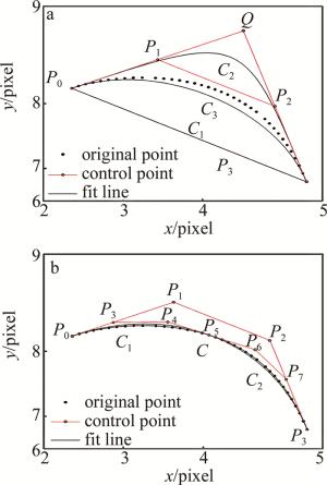
Figure 5. Triangular dichotomy
式中,εi为每点的实际误差,εsum为所有拟合点实际误差的和。
假设εsum最大允许误差为εs, 若abs(εsum)<εs, 跳到步骤(3);不满足则到步骤(2)。
(2) tleft对应的误差和εsum, C1>0, tright对应的误差和εsum, C2<0, 由二分法求出中间位置参量tmid=(tleft+tright)/2=0.5, P1和P2位置在QP0和QP3中点,C3即为新的曲线,求出abs(εsum, C3)>εs且εsum, C3>0,则tmid替代tleft,求取下一个tmid,直到满足abs(εsum)<εs。
(3) 如图 5b所示, C为第1次满足条件的贝塞尔曲线。假设单点所允许的最大误差为eper, 若emax<eper, 该部分拟合完成;否则需要将进一步拟合。取出原始点集和拟合曲线C的交点P5(误差小于两端的点),将点集以P5为分界点分成两个点集再进行拟合,分别得到C1和C2,经计算均满足最大误差,不用进行下一步拆分,否则继续进行拆分。
经过上述步骤,可将点集中所有点的误差控制在eper以下,拟合成3阶贝塞尔曲线,如图 2d所示,红色控制点计算得到的黑色曲线与初始点集的最大误差不超过0.02pixel,并且可根据实际加工误差需求进行换算调整当前误差值。
-
经过上述两个步骤,线段点集拟合成仅由直线和贝塞尔曲线组合成的实体,根据不同的标刻分辨率,采用不同的步距进行统一分割。除此之外,经过曲线化后,具备了另一个性质,即曲率。如图 6a所示,在选择下一个插入点Ti时,计算TiTi-1中点P与贝塞尔曲线上两点的参量t的中点T的距离,作为误差值δ[18]:
$ \delta=\mid \frac{T_{i-1}+T_{i}}{2}-P\left(\frac{u_{i-1}+u_{i}}{2}\right)| $
(5) 
Figure 6. Chord height error segmentation
式中, ui为对应点的贝塞尔参量值,中间值u=(ui-1+ui)/2,P通过n阶贝塞尔曲线公式[19]计算:
$ \left\{ {\begin{array}{*{20}{l}} {P(u) = \sum\limits_{j = 0}^n {{b_j}} {B_{j,n}}(u),(0u1)}\\ {{B_{j,n}}(u) = C_n^j{u^j}{{(1 - u)}^{n - j}},(j = 0,1, \cdots ,n)} \end{array}} \right. $
(6) 式中,bj为控制点。
经过迭代计算使得最终误差δ满足需求,如图 6b所示,对于曲率大的位置,同一误差会求出更小的步距,最终完成实体中所有曲线和直线的插补[20]。将数据以曲线方式保存,标刻时根据放大比例大小、曲率大小以不同步距进行适应性插补,图 6c和图 6d中分别是低高放大倍数下的选取的标刻点。
-
振镜标刻幅面大小110mm×110mm,对应的分辨率65535×65535,以图 2a和图 2d作为输入,激光参量为:频率50kHz,平均功率20W,标刻速率500mm/s,分别在36×和72×放大倍数下在黑色相纸上进行标刻,1pixel对应实际加工距离分别为0.06mm和0.12mm,故0.02pixel的拟合误差换算成加工幅面下实际误差分别约为1μm和2μm,其中拟合曲线的标刻点在图 6中计算得出。使用工业相机下进行观察,如图 7a所示,在低放大倍数下,原始点由于分布过密,导致在对应标刻点出现了激光烧蚀现象,标刻线为黄色,且刻蚀线变粗,在图 7c中,则是在高放大倍数下加工,放大后相邻点间距变大,烧蚀现象有所减轻,但仍然存在。图 7b和图 7d中,拟合控制点在低、高放大倍数下,标刻点都会进行适应性分布,没有出现激光烧蚀或者锯齿现象,标刻线均匀,都具有良好的标刻效果。
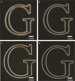
Figure 7. Image which marked by original point set and fitted control points at different resolutions
表 1中分别从标刻点数、加工时间、加工质量和有无激光烧蚀等方面对4组数据及标刻图作出对比。拟合误差不超过2μm,并且在不同分辨率下标刻点随之改变,保证标刻质量,解决了由数据点过密引起的激光烧蚀问题,也一定程度上减少了加工时间。
Table 1. Comparison of marking quality between original point set and fitted control points at different magnification
original point set fitted point set low magnification (36×) high magnification (72×) low magnification (36×) high magnification (72×) number of control point none none 40 40 mark point 1181 1181 207 288 fitting error/μm 0 0 1 2 processing time/ms 19 18 4 5 has laser ablation yes yes no no processing quality low low high high -
针对振镜激光加工中原始数据点集过密造成激光烧蚀的问题,提出了一种将原始点集经过稀疏化、曲线点集选取分段、三角二分贝塞尔曲线拟合生成曲线控制点集,在加工时根据放大倍数大小和曲率大小进行适应性分割的方法,拟合后的加工误差不超过2μm,数据量大幅度压缩,解决了低放大倍数下激光烧蚀问题,高放大倍数下也保证了加工质量,并提高了加工效率。研究结果为一些高密集数据激光加工优化提供了参考。
基于点集贝塞尔曲线优化的激光振镜加工算法
Laser galvanometer processing algorithm based on Bezier curve optimization of point set
-
摘要: 为了解决激光振镜加工中由于数据点集过于密集导致激光在单点停滞时间过长引起激光烧蚀问题,将原始数据点集经过稀疏化、曲线点集分段、三角二分法贝塞尔曲线拟合数据处理,转换成由少量直线和曲线构成的实体,在激光路径输出时,根据输出放大倍数的大小及曲线曲率大小对曲线进行整体的适应性插补,从而解决因放大倍数不同引起的数据点过密或过疏的问题,并通过对前后数据以不同的标刻分辨率进行标刻。结果表明,在保证拟合后的加工误差不超过2μm下,解决了数据过密引起的激光烧蚀问题;在高放大倍数下也具有平滑的加工效果,具有更高的加工效率和质量。此研究为高密集数据激光加工提供了参考,在高质量激光加工领域如激光精密刻蚀有良好的应用前景。Abstract: In order to solve the problem of laser ablation due to the long time laser stop at the single point caused by the excessive density of the data point set in laser galvanometer processing, the original data point set was processed by thinning, curve point set segmentation, and triangular dichotomy Bezier curve fitting data processing, which was converted into an entity composed of a few line and curve. When laser marking, the curve was adaptively interpolated according to the output resolution and curve curvature to solve the problem of too dense or too sparse data points caused by different magnification. By marking the original and processed data with different marking magnification, the results show that the fitted data eliminates the laser ablation phenomenon caused by over-density of the data under the guaranteed 2μm accuracy of the original data. It also has a smoother marking effect at high magnification, as well as a higher marking efficiency and quality. It provides a reference for high density laser processing and has a good application prospect in the field of high quality laser processing such as laser precision etching.
-
Figure 2. The process of point set fitting
a—original point set b—point set thinning c—point set split d—final fitted curve
Figure 4. Curve point set criterion and segmentation
a—angle criterion b—third-order inflection point c—curve segment
Figure 6. Chord height error segmentation
a—schematic diagram of chord height error segmentation b—segmentation diagram c—marking points at low magnification times d—marking points at high magnification times
Figure 7. Image which marked by original point set and fitted control points at different resolutions
a—original point set at 36× b—fitted control point at 36× c—original point set at 72× d—fitted control point at 72×
Table 1. Comparison of marking quality between original point set and fitted control points at different magnification
original point set fitted point set low magnification (36×) high magnification (72×) low magnification (36×) high magnification (72×) number of control point none none 40 40 mark point 1181 1181 207 288 fitting error/μm 0 0 1 2 processing time/ms 19 18 4 5 has laser ablation yes yes no no processing quality low low high high  下载: 导出CSV
-
[1] LIU J J, YAN P, LI G Zh, et al. Laser processing technology[J]. Physics Bulletin, 2009(8): 54-56(in Chinese). [2] XU K K. Research on high-speed galvanometer scanning laser 3-D printing control system[D]. Wuhan: Huazhong University of Science and Technology, 2017: 4-55(in Chinese). [3] WANG B, LIU X D, LI J H, et al. Research on dot laser drilling location algorithm based on neighborhood features[J]. Laser Technology, 2019, 43(5): 1-6(in Chinese). [4] LUO X, LI J, LUCAS M. Galvanometer scanning technology for laser additive manufacturing[J]. Proceedings of the SPIE, 2017, 10095: 1009512. [5] GAO X L. Binarization of image processing in laser engraving[J]. Laser Journal, 2004, 25(4): 76-78(in Chinese). [6] WANG J P, LI Zh J, FAN X H. Analysis of laser marking system and process parameters[J]. Optics and Optoelectronic Technology, 2005, 3(3): 32-35(in Chinese). [7] XU L P, HU B. A conversion method from JPG image to PLT file[J]. Laser Journal, 2005, 26(6): 50-51(in Chinese). [8] LIU T L, HU B, YING H Sh, et al. Experimental research on laser marking error[J]. Laser Journal, 2007, 28(1): 33-34(in Chinese). [9] LIAO P, YANG D Y, LIU R X. An optimization algorithm of truetype font contour line approximation in laser marking[J]. Laser Technology, 2016, 40(4): 483-486(in Chinese). [10] HAN X L, LIU Sh J. Extension of cubic uniform B-spline curve[J]. Journal of Cofmputer Aided Design and Graphics, 2003, 15(5): 576-578(in Chinese). [11] PIEGL L, TILLER W. The NURBS book[M]. 2th ed. New York, USA: Springer, 1997: 410-419. [12] LIU M Z, GUO Q J, WANG S Q. Adaptive B-spline curve fitting based on regular asymptotic iterative approximation[J]. Journal of Graphics, 2018, 39(2): 287-294(in Chinese). [13] SELINGER P. Potrace: A polygon-based tracing algorithm[DB/OL]. (2003-9-20)[2020-10-16]. http://potrace.sourceforge.net/potrace.pdf. [14] YAO P P, FAN Zh, ZHANG S L. Improved Potrace jacquard image vectorization algorithm[J]. Sensors and Microsystems, 2014, 33(4): 125-127(in Chinese). [15] YU X J, PENG L Zh. A new algorithm for curve contour extraction in binary image[J]. Journal of Image and Graphics, 2002, A7(3): 272-275(in Chinese). [16] ZHANG Ch C, SUN X M, ZHU T Y. Research on AutoCAD's DXF file format and its conversion interface[J]. Microcomputer Applications, 2001, 17(8): 54-55 (in Chinese). [17] HETAL N F, AKASH B P, DIVYANG D P, et al. A review on approaches for handling bezier curves in CAD for manufacturing[J]. Procedia Engineering, 2014, 97: 1155-1166. doi: 10.1016/j.proeng.2014.12.394 [18] YANG J. Research and implementation of key algorithms for forward-looking direct interpolation of NURBS curves in high-speed machining numerical control systems[D]. Hangzhou: Zhejiang University, 2019 : 4-32(in Chinese). [19] XU Y M, WEN Sh Ch. Study on Bezier curve recursive algorithm[J]. Journal of Hengyang Normal University, 2007, 28 (6): 113-115(in Chinese). [20] KUANG Y, WU Y F, WU B, et al. Extraction and optimization of marking path in laser marking system[J]. Laser Technology, 2012, 36(1): 131-133(in Chinese). -

 点击查看大图

计量
- 文章访问数: 6657
- HTML全文浏览量: 4998
- PDF下载量: 33
- 被引次数: 0
