 网站地图
网站地图


-
汽车保有量的大幅增加导致了能源消耗和环境污染等诸多问题,而汽车轻量化是解决全球环境负担的关键环节[1-2]。铝-钢异种金属连接的复合结构件,充分结合了铝合金优异的轻质、耐腐蚀性能、易于加工性和钢的高强度、高延展性、韧性等优势,在汽车轻量化的研究进程中成为一个热点[3-4]。激光传输焊接作为一种新兴的特种加工技术,具有焊接速度快、精度高、热影响区小和可精确控制工艺参量及作用时间等优势,已被广泛应用于铝-钢异种金属的连接中[5-6]。然而,铝钢两种金属的物理、化学性能差异较大,相互溶解度也较低,因此在焊接冷却过程中极易在反应界面形成如FeAl, FeAl2, Fe2Al5和Fe4Al13等硬脆的Al-Fe金属间化合物,降低焊接接头的韧性和延展性。若工艺参量不当甚至出现焊接裂纹,还会严重影响其强度[7]。
激光熔钎焊结合了熔焊和钎焊的优点,可有效控制铝-钢反应层金属间化合物厚度,提高连接强度。焊接过程中由于铝合金的光反射率较高,会导致激光能量利用率降低。选择送粉的方式进行激光熔钎焊的优势在于,一方面粉末颗粒落到铝合金表面可增加其粗糙度,提高工件对激光束的吸收率; 另一方面,部分激光束经工件表面反射作用于粉末束流中,会被粉末再次反射重新作用于工件,从而进一步提高了焊接过程中对激光能量的利用率。LIU等人[8]进行了铝-钢激光送粉熔钎焊试验,通过调控激光工艺参量实现了铝钢连接,将反应层金属间化合物厚度控制在6μm~7μm,强度达到174N/mm。ZHANG等人[9]研究了不同填充粉末对铝-钢激光送粉熔钎焊接头性能的影响。研究发现,采用AlSi12填充粉末时有效改善了接头成形质量,若将反应层金属间化合物厚度控制在4μm左右,接头强度可达到铝合金母材的67.6%。
铝-钢搭接激光焊接过程中,由于两材料的熔点、导热性及熔体粘性存在较大差异,因此焊接时激光束焦点位置需要设定一定偏移量,才能使得铝合金和填充粉末合理熔化,提高接头整体质量[10-11]。激光偏移量可有效改变激光束的作用位置和能量分布,从而对焊缝整体成形、金属间化合物及力学性能产生较大影响[12-13]。本文中采用纯铝粉末作为送粉填充粉末,进行铝-钢激光熔钎焊试验,研究了添加钎剂对接头成形和激光偏移量对铝-钢钎焊接头润湿铺展效果、金属间化合物厚度和力学性能等的影响,并对铝-钢钎焊接头进行了机理研究。
-
试验材料选用尺寸为100mm×50mm×1.5mm的2024铝合金和100mm×50mm×1.5mm的08Al钢。焊前将铝合金浸泡在饱和氢氧化钠溶液中去除表面氧化膜,然后用HF(质量分数为0.03)+HCl(质量分数为0.07)混合溶液进行中和,最后用丙酮对铝合金和钢表面进行清洗。试验中采用的填充材料是粒度为70μm~110μm的纯铝粉末,纯铝粉末作为本实验中的钎料。为提高钎料的润湿铺展效果,采用Nocolok钎剂,主要由KAlF4和K3AlF6组成。材料的化学成分如表 1和表 2所示。
Table 1. Chemical composition of 2024 aluminum alloy (mass fraction)
Si Fe Cu Mn Mg Cr Zr Zn Ti Al 0.50 ≤0.50 3.80~4.90 0.30~1.00 1.20~1.80 ≤0.10 — ≤0.25 — balance Table 2. Chemical composition of 08Al steel (mass fraction)
C Si Mn Cr Ni P S Al Fe 0.05~0.11 ≤0.03 0.25~0.65 ≤0.10 ≤0.30 ≤0.035 ≤0.035 ≤0.07 balance -
采用德国Trumph公司生产的HL4006D型Nd:YAG激光器与KUKA机器人组成的智能焊接系统,激光波长λ=1064nm,光束质量因子为25mm·mrad,焦点位置光斑直径D=0.6mm,焦点处的激光能量分布如图 1所示。送粉设备为PFL-2A型送粉器,激光焊接头与送粉头采用旁轴连接方式,呈30°夹角。图 2所示为激光焊接设备实物图。图 3所示为焊接过程示意图。
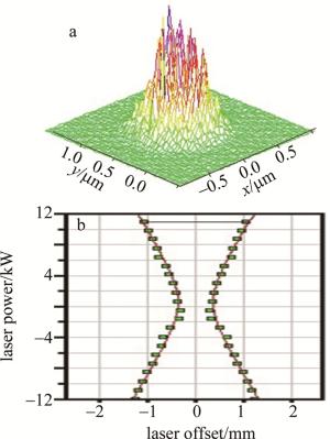
Figure 1. Energy distribution map of laser beam
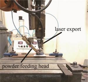
Figure 2. Physical drawing of laser welding equipment
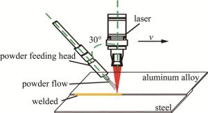
Figure 3. Schematic diagram of the welding process
本试验中采用铝上钢下的搭接焊接方式,在焊接前将钎剂与酒精的混合物均匀涂抹于钢表面,激光束采用垂直入射方式,送粉头旁轴送粉。试验的具体工艺参量如表 3所示。
Table 3. Laser fusion-brazing conditions
processing parameters value laser power P 3.5kW laser offset Δd 0mm~1.6mm speed of welding v 1.2m/min powder feeding speed Qp 0.47g/min defocusing distance Δf +12mm Ar shielding gas flow rate fg 6L/min 焊后用线切割制取金相试样和拉伸试样,采用体式显微镜对焊缝的宏观形貌进行观测,并测量焊缝的润湿角和连接宽度,润湿角的测量方法如图 4所示。采用Keller试剂(HNO3(质量分数为0.025)+HCl(质量分数为0.015)+HF(质量分数为0.01)水溶液)对铝侧进行腐蚀,用硝酸酒精溶液(质量分数为0.04)对钢侧进行腐蚀,然后用金相显微镜和扫描电镜对焊缝微观形貌进行观测,并测量金属间化合物厚度以及各元素的分布情况;采用拉伸试验机测量焊缝的力学性能。
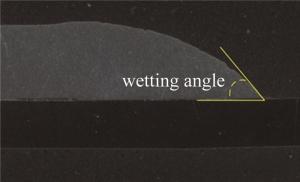
Figure 4. Method of measurement of wetting angle
-
图 5中对比了有无添加钎剂对铝-钢激光熔钎焊焊缝成形的影响。由图中可看出,未添加钎剂时,焊缝连接宽度较小,焊缝出现咬边和塌陷等缺陷,且润湿角已经超过90°,焊趾区域未实现有效连接,在承受拉伸剪切作用力时,易在缺陷处和焊趾处应力集中而发生脆断,其连接强度非常低。在添加钎剂之后,焊缝连接宽度显著增加,焊缝成形均匀饱满,咬边和塌陷等缺陷得到改善,且润湿角减小,焊趾区域未见开裂现象。这是因为铝钢两种金属物理化学性能差异较大,且铝表面附着一层氧化铝,使得铝熔体在钢侧的润湿铺展性较差。然而,添加钎剂之后,由于钎剂熔点较低,焊接时钎剂首先熔化,熔化的钎剂会有效去除母材表层氧化膜,促进表面活化,减小表面张力,提高熔融钎料在钢表面的润湿铺展性,有效实现铝-钢异种金属连接。
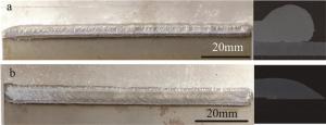
Figure 5. Effect of brazing flux on brazing seam forming of aluminum-steel a—with brazing flux b—without brazing flux
-
激光偏移量是指激光束焦点的中心位置偏离焊缝中心一定的距离。激光偏移量的选择与设定可有效调控作用在焊件上的激光能量分布和焊缝中的热输入量,从而影响焊缝的整体性能。本试验为填粉熔钎焊,要保证铝合金与填充粉末充分熔化并与钢反应,因此以激光束向铝合金侧偏移为正偏移量。激光偏移量的示意图如图 6所示。

Figure 6. Schematic diagram of laser offset
图 7所示为激光偏移量Δd=0mm~1.6mm时焊缝的宏观形貌和截面形貌。图 8所示为激光偏移量对焊缝润湿角的影响。随着偏移量的增加,润湿角整体呈增大趋势。图 9所示为激光偏移量对焊缝力学性能的影响。焊缝的平均机械抗力随偏移量增加呈先增大后减小的趋势。
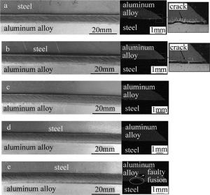
Figure 7. Effect of laser offset on macro-morphology of welded a—Δd=0mm b—Δd=0.4mm c—Δd=0.8mm d—Δd=1.2mm e—Δd=1.6mm
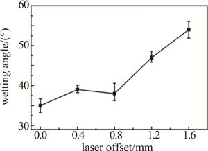
Figure 8. Effect of Laser offset on weld wetting angle
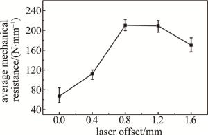
Figure 9. Effect of laser offset on mechanical properties of weld
由图中可看出,在偏移量为0mm和0.4mm时,钢侧吸收大量的激光能量而发生熔化,铝合金母材和钎料熔体在高温作用下粘性系数和表面张力减小,使其在钢母材的润湿性提高,因此润湿角较小。然而由于钢母材大量熔化导致Fe与Al在钎焊界面产生大量硬脆金属间化合物,当反应层的金属间化合物的厚度达到一定值时便会出现裂纹[14],本试验中偏移量为0mm和0.4mm时,在铝-钢熔钎焊界面出现开裂现象,因此其连接强度非常低。通过调整激光偏移量可直接决定钢和铝的熔化量,在偏移量为0.8mm时,焊缝成形均匀,无明显缺陷,此时焊缝的抗拉性能最好,平均机械抗力达到210N/mm。随着激光偏移量继续增加,热源中心位置偏离焊趾区,由于激光能量为高斯热源分布,四周能量分布较低,导致焊趾区吸收热量不足,此时铝熔体粘性系数相对较大,发生团聚,致使在钎焊界面发生局部未熔合现象,且铝熔体流动性较差,在钢表面的润湿铺展性较差,润湿角达到55°左右,出现咬边和塌陷等缺陷,其连接强度明显降低。
图 10所示为不同激光偏移量对铝-钢熔钎焊界面金属间化合物厚度及分布的影响。由图中可发现,激光偏移量为0mm和0.4mm时,界面存在裂纹并未完全熔合发生连接。随着激光偏移量的增大,钎焊界面的“条状”金属间化合物逐渐均匀平缓且厚度减小,由激光偏移量为0.8mm时的8μm减小到激光偏移量为1.6mm时的6.3μm,金属间化合物厚度在该范围时接头的整体力学性能较好[15],且弥散于铝合金中的“针状”金属间化合物的数量和尺寸逐渐减小,这是因为当激光偏移量增加时,钢母材直接接收的激光能量减少,使得钢基材料中的铁元素和锰元素向铝合金熔体中的溶解扩散过程减缓,导致金属间化合物厚度和数量减少。
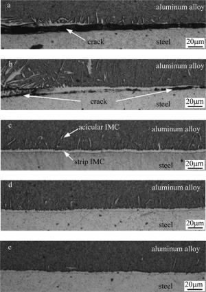
Figure 10. Effect of laser offset on thickness and distribution of intermetallic compounds in welds a—Δd=0mm b—Δd=0.4mm c—Δd=0.8mm d—Δd=1.2mm e—Δd=1.6mm
-
图 11所示为激光功率3.5kW、激光偏移量0.8mm、离焦量+12mm、焊接速率1.2m/min、送粉速率0.47g/min时,铝-钢激光熔钎焊接头的微观组织形貌。熔合区主要由铝合金和填充的纯铝粉末组成,以柱状枝晶组织为主;熔钎焊界面分布着厚度为8μm左右均匀连续的条状金属间化合物以及清晰可见“针状”金属间化合物。
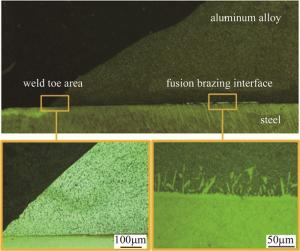
Figure 11. Effect of laser offset on thickness and distribution of intermetallic compounds in welds
为了观测钎焊界面Al元素和Fe元素的分布情况,对铝-钢激光熔钎焊界面进行能量透射光谱(energy dispersive spectroscopy, EDS)面扫描分析,得到如图 12所示的结果。从图中可明显看出, 界面中间反应层分布着Al元素和Fe元素,共同组成了“条状”金属间化合物,焊接过程中Fe元素向熔融铝合金和钎料中溶解扩散,在凝固后的熔合区形成“针状”金属间化合物。
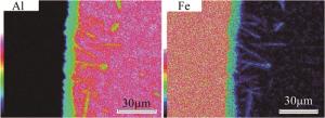
Figure 12. Scanning results of EDS of laser brazing interface between aluminum and steel
图 13所示为铝-钢激光熔钎焊界面扫描电镜照片以及进行EDS点扫位置图。分别对钢母材与“条状”金属间化合物的过渡区A点,“条状”金属间化合物区B点,“条状”金属间化合物与“针状”金属间化合物过渡区C点和“针状”金属间化合物区D点进行EDS点扫描,得到如表 4所示的各测量点的Al, Fe元素的质量分数。根据Al-Fe二元相图,铝-钢异种金属焊接时可形成FeAl, FeAl2, Fe2Al5和Fe4Al13等金属间相,其中FeAl2是一种亚稳定相,在熔体凝固后将会消失[16]。
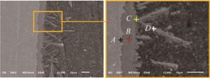
Figure 13. EDS spot scanning position of laser brazing interface between aluminum and steel
Table 4. EDS spot scanning results of laser brazing interface between aluminum and steel
point element(mass fraction) atom ratio of Al-Fe Al Fe A 0.0184 0.9816 0.02 B 0.6134 0.3867 1.59 C 0.7315 0.2685 2.72 D 0.8328 0.1673 4.98 根据金属间相形成过程中吉布斯自由能的变化规律,当Fe2Al5的吉布斯自由能变化小于Fe4Al13时,Fe2Al5相会先于Fe4Al13相的形成,然后随着温度的降低,Fe元素在铝熔体中的溶解度逐渐降低,Fe原子会在向铝熔体扩散溶解过程中逐渐沉淀下来,最终在铝基材料一侧形成“针状”金属间相[8, 17]。
为了进一步验证铝-钢异种金属激光熔钎焊界面各相的种类,将拉伸断裂后无残留钢基体的铝合金一侧(将拉伸剥离断裂后的铝合金一侧浸泡在硝酸酒精溶液中以去除残留的钢基体)进行X射线衍射(X-ray diffraction, XRD)物相分析,得到如图 14所示的物相分析结果。由图中可知, 在铝-钢钎焊界面区主要存在3种Al-Fe金属间相,分别是FeAl, Fe2Al5和Fe4Al13,综合EDS和XRD的数据结果可得知,A点的物相主要为α-Fe固溶体,B点的物相有FeAl和Fe2Al5,C点的物相主要为Fe2Al5,D点的物相主要有Fe4Al13和α-Al固溶体。
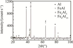
Figure 14. X-ray diffraction diagram of brazing interface of aluminum steel
图 15为铝-钢激光钎焊拉伸断裂形貌。拉伸断裂失效形式为典型的剥离断裂,在断裂面存在许多微小的气孔,该位置处于靠近钢母材侧的熔化区,气孔区域存在应力集中现象,导致拉伸过程中首先由此处断裂。图 16为铝-钢激光钎焊拉伸断口的扫描电子显微镜(scanning electron microscope, SEM)照片。由图中可看出,断裂形式为典型准解理断裂。
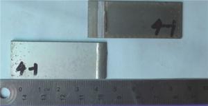
Figure 15. Macro morphology of tensile fracture of aluminum-steel laser brazing
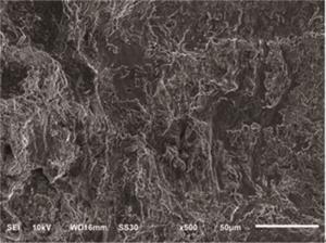
Figure 16. SEM photos of tensile fracture surface of aluminum-steel laser brazing
-
本文中采用激光填粉熔钎焊的方式成功实现了铝-钢异种金属连接。
(1) 钎剂的添加有效提高了铝合金和钎料熔体在钢母材表面的润湿铺展性,改善了接头的整体成形,减少焊接缺陷。
(2) 激光偏移量对钎焊接头成形和力学性能有重要影响,当激光偏移量为0.8mm时,焊缝表面缺陷明显得到改善,接头的润湿角较小,“条状”金属间化合物厚度为8μm,在最佳金属间化合物厚度范围之内,其抗拉性能最好,其平均机械抗力达到210N/mm。
(3) 对铝-钢钎焊界面进行EDS能谱分析和XRD物相分析,综合其测试结果,界面反应层由FeAl, Fe2Al5和Fe4Al13这3种金属间相组成;拉伸测试表明接头为典型的准解理断裂。
铝-钢异种金属激光熔钎焊工艺研究
Study on laser powder filling brazing technology of aluminum-steel dissimilar metals
-
摘要: 为了实现高强度铝-钢钎焊接头,以车用08Al钢和铝合金为试验对象,以填粉方式选用纯铝粉末作为钎料,进行了异种金属激光熔钎焊接试验研究。综合能量散射光谱能谱分析和X射线荧光衍射物相分析,接头界面处的金属间化合物主要有FeAl,Fe2Al5和Fe4Al13。研究了添加钎剂对接头整体成形及激光偏移量对接头形貌和力学性能的影响。结果表明,钎剂的添加改善了接头成形缺陷,提高了焊趾区的润湿性;当激光偏移量为0.8mm~1.6mm时,形成了有效的熔焊接头,且随着激光偏移量的增加,接头润湿角由35°增加到54°,反应层的金属间化合物厚度逐渐减小,抗拉性能呈先提高后降低的趋势;在激光偏移量为0.8mm时,接头润湿角为38°,反应层金属间化合物厚度8μm,平均机械抗力达到210N/mm,具有较高的工程应用价值;焊缝润湿角、连接宽度和反应层金属间化合物厚度共同决定了接头的机械抗力水平。该研究对于保证车身激光焊接质量提供了技术支持和重要的指导意义。Abstract: In order to realize the brazing joint of high strength aluminum-steel, took 08Al steel and aluminum alloy for automobile were taken as the experimental object, and pure aluminum powder was selected as solder by filling powder to carry on the experimental study of dissimilar metal laser fusion brazing. Based on energy dispersive spectroscopy energy spectrum analysis and X-ray diffraction phase analysis, the main intermetallic compounds at the interface of the joint are FeAl, Fe2Al5 and Fe4Al13. The effect of adding brazing flux on the whole forming of the joint and the effect of laser offset on the morphology and mechanical properties of the joint were studied. The results show that the addition of the bonding agent improves the joint forming defect and the wettability of the toe area. When the laser offset is 0.8mm~1.6mm, an effective fusion welding joint is formed. With the increase of laser offset, the wetting angle of the joint increases from 35° to 54°, while the thickness of intermetallic compounds in the reaction layer decreases gradually, and the tensile properties of the reaction layer increase at first and then decrease. When the laser offset is 0.8mm, the wetting angle of the joint is 38°, the thickness of the intermetallic compound in the reaction layer is 8μm, and the average mechanical resistance is 210N/mm, which has high engineering application value. The wetting angle of the weld, the width of the joint and the thickness of the intermetallic compound in the reaction layer determine the mechanical resistance level of the joint. The research will provide technical support and important guidance for ensuring the quality of laser welding of the body.
-
Key words:
- laser technique /
- laser fusion-brazing /
- laser offset /
- aluminum-steel dissimilar metals
-
Figure 5. Effect of brazing flux on brazing seam forming of aluminum-steel a—with brazing flux b—without brazing flux
Figure 7. Effect of laser offset on macro-morphology of welded a—Δd=0mm b—Δd=0.4mm c—Δd=0.8mm d—Δd=1.2mm e—Δd=1.6mm
Figure 10. Effect of laser offset on thickness and distribution of intermetallic compounds in welds a—Δd=0mm b—Δd=0.4mm c—Δd=0.8mm d—Δd=1.2mm e—Δd=1.6mm
Figure 11. Effect of laser offset on thickness and distribution of intermetallic compounds in welds
Figure 12. Scanning results of EDS of laser brazing interface between aluminum and steel
Figure 13. EDS spot scanning position of laser brazing interface between aluminum and steel
Table 1. Chemical composition of 2024 aluminum alloy (mass fraction)
Si Fe Cu Mn Mg Cr Zr Zn Ti Al 0.50 ≤0.50 3.80~4.90 0.30~1.00 1.20~1.80 ≤0.10 — ≤0.25 — balance  下载: 导出CSV
Table 2. Chemical composition of 08Al steel (mass fraction)
C Si Mn Cr Ni P S Al Fe 0.05~0.11 ≤0.03 0.25~0.65 ≤0.10 ≤0.30 ≤0.035 ≤0.035 ≤0.07 balance
下载: 导出CSV
Table 3. Laser fusion-brazing conditions
processing parameters value laser power P 3.5kW laser offset Δd 0mm~1.6mm speed of welding v 1.2m/min powder feeding speed Qp 0.47g/min defocusing distance Δf +12mm Ar shielding gas flow rate fg 6L/min
下载: 导出CSV
Table 4. EDS spot scanning results of laser brazing interface between aluminum and steel
point element(mass fraction) atom ratio of Al-Fe Al Fe A 0.0184 0.9816 0.02 B 0.6134 0.3867 1.59 C 0.7315 0.2685 2.72 D 0.8328 0.1673 4.98
下载: 导出CSV
-
[1] KOUADRI D A. Study of metallurgic and mechanical properties of laser welded heterogeneous joints between DP600 galvanised steel and aluminium 6082[J]. Materials & Design, 2014, 54: 184-195. [2] MILLER W S, ZHUANG L, BOTTEMA J, et al. Recent development in aluminium alloys for the automotive industry[J]. Materials Science & Engineering, 2000, A280(1): 37-49. [3] SCHUBERT E, KLASSEN M, ZERNER I, et al. Light-weight structures produced by laser beam joining for future applications in automobile and aerospace industry[J]. Journal of Materials Processing Technology, 2001, 115(1): 2-8. [4] HADDADI F, ABU-FARHA F. The effect of interface reaction on vibration evolution and performance of aluminium to steel high power ultrasonic spot joints[J]. Materials & Design, 2016, 89: 50-57. [5] CHEN Y Ch, LUO Z Y, HAN Sh G, et al. Study on microstructure and properties of 5mm thick copper laser welded joint[J]. Laser Technology, 2019, 43(2): 212-216(in Chinese). [6] ZHOU J, LIU Sh Y, ZHANG F L. Microstructure and formation mechanism of laser self-propagating bonding CFRTP/ aluminum joint[J]. Laser Technology, 2019, 43(2): 147-153(in Chinese). [7] MECO S, PARDAL G, GANGULY S, et al. Application of laser in seam welding of dissimilar steel to aluminium joints for thick structural components[J]. Optics and Lasers in Engineering, 2015, 67: 22-30. doi: 10.1016/j.optlaseng.2014.10.006 [8] LIU J, JIANG S, SHI Y, et al. Laser fusion-brazing of aluminum alloy to galvanized steel with pure Al filler powder[J]. Optics & Laser Technology, 2015, 66: 1-8. [9] ZHANG Y, LI F, GUO G, et al. Effects of different powders on the micro-gap laser welding-brazing of an aluminium-steel butt joint using a coaxial feeding method[J]. Materials & Design, 2016, 109: 10-18. [10] WELDING SOCIETY of CHINA MECHANICAL ENGINEERING SOCIETY. Welding manual (Vol.2): Welding of materials[M]. Beijing: Mechanical Industry Publishing House, 2009: 57-65(in Chinese). [11] WEN Zh, YU Zh H, YAN G H, et al. Effect of laser beam offset on microstructure and properties of dissimilar metal welded joints[J]. Welding Technique, 2017, 46(12):12-15(in Chinese). [12] QIAN W, CUI L, MA B, et al. Study on laser deep melting brazing technology of medium and heavy plate aluminum/steel dissimilar materials[J]. Application of Laser, 2015, 35(4):29-34(in Chin-ese). [13] SONG Zh H, WU A P, YAO W, et al. Effect of beam offset on microstructure and properties of titanium/aluminum dissimilar alloy laser welded joints[J]. Welding Journal, 2013, 34(1): 105-108(in Chinese). [14] SIERRA G, PEYRE P, BEAUME F D, et al. Galvanised steel to aluminium joining by laser and GTAW processes[J]. Materials Characterization, 2008, 59(12): 1705-1715. doi: 10.1016/j.matchar.2008.03.016 [15] SONG J L, LIN S B, YANG C L, et al. Spreading behavior and microstructure characteristics of dissimilar metals TIG welding-brazing of aluminum alloy to stainless steel[J]. Materials Science & Engineering, 2009, A509(1/2): 31-40. [16] MASSALSKI T B, OKAMOTO H, SUBRAMANIAN P R, et al. Binary alloy phase diagrams[M].Tokyo, Japan: ASM International, 1990: 17-56. [17] SHI Y, HE C, HUANG J, et al. Thermodynamic analysis of the forming of intermetallic compounds on aluminum-steel welding interface[J]. Journal of Lanzhou University of Technology, 2013, 39(4): 45-47. -

 点击查看大图

计量
- 文章访问数: 4626
- HTML全文浏览量: 2935
- PDF下载量: 18
- 被引次数: 0
