-
大气气溶胶是大气环境中组成复杂、危害较大的污染物之一, 一直是当今大气科学和环境科学等领域的重要研究内容[1-2]。激光雷达因为具有时空分辨率高以及测量精度高等特点,成为探测气溶胶分布的一种重要的主动遥感工具[3-5]。目前用于探测大气气溶胶的激光雷达主要是米散射激光雷达和偏振激光雷达,米散射激光雷达可以获得气溶胶粒子的空间相对分布[6-7],偏振激光雷达可以获得气溶胶粒子的非球形特征[8-9]。而多波长的激光雷达系统不仅可以获得不同波长的气溶胶消光系数,并且可以依据不同波长的气溶胶消光系数算出表征粒子特性的Ångström指数等特性。
CHI等人用研制的532nm和1064nm的双波长米散射激光雷达探测大气气溶胶消光特性[10]。DI等人利用多波长激光雷达(355nm, 532nm, 1064nm)探测多种天气气溶胶光学特性[11]。本文中所介绍的污染气体探测激光雷达是中国科学院安徽光学精密机械研究所从2012年开始研发的新一代测污雷达[12-14],利用该激光雷达对安徽淮南上空的大气进行探测,然后分析安徽淮南大气的气溶胶消光特性、能见度和Ångström指数变化规律。
-
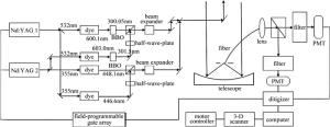
该测污激光雷达系统包含4个激光发射波长,分别是300.05nm, 301.5nm, 448.1nm和446.6nm,其中探测二氧化硫的波长对为λ1, on=300.05nm和λ1, off=301.5nm,探测二氧化氮的波长对为λ2, on=448.1nm和λ2, off=446.6nm。系统主要由激光发射、信号接收和信号采集及系统控制三大主要部分组成,其具体系统结构框图如图 1所示。图中BBO(barium boron oxide)为偏硼酸钡, PMT(photomultiplier)是光电倍增管。
系统采用2台固体Nd: YAG激光器抽运4台染料激光器方式产生所需波长,2台Nd: YAG激光器交替产生10Hz基频1064nm激光束, 基频光1064nm激光束经过倍频晶体产生532nm的激光,然后,532nm激光与剩余的1064nm激光同时穿过三倍频晶体产生355nm的激光,这样,2台固体Nd: YAG激光器产生了4束激光。其中两束交替出射的355nm激光分别去抽运两台染料激光器,分别产生446.6nm作为弱吸收波长λ2, off和448.1nm作为强吸收波长λ2, on,用来测量边界层大气二氧化氮浓度的分布。另外两束交替出射的532nm激光分别去抽运两台染料激光器,分别产生600.1nm和603nm的激光束,600.1nm和603nm的激光束, 再分别经过BBO晶体进行倍频,产生300.05nm作为强吸收波长λ1, on和301.5nm作为弱吸收波长λ1, off,用来测量边界层的大气二氧化硫。这样探测二氧化硫和二氧化氮的激光束已经获得。
446.6nm的激光经过半波片后和448.1nm激光经合束和伽利略式扩束器6倍扩束,导入45°转向镜。301.5nm的激光也经过半波片后和300.05nm激光经合束和伽利略式扩束器6倍扩束,也导入45°转向镜。然后这4束激光一起经过3维扫描子系统的两块大口径平面镜射向大气中,4束波长的光经过传输路径上的大气分子和大气气溶胶所吸收和散射,大气后向散射光被350mm的3维近牛顿式扫描望远镜接收。通过计算机改变3维扫描系统的电机转动位置,可以改变激光发射的方向,从而实现对大气的水平、垂直和不同角度空间的探测。为了减小大气背景噪声的干扰, 在望远镜后面采用小孔光阑限制视场角为0.2mrad~2mrad。然后通过一根芯径为1.5mm的传能光纤导入准直透镜进行准直,准直后的光经过分光系统将信号分成SO2通道和NO2通道,两个通道上分别加有相对应的滤光片和衰减片,两通道的信号分别被对应的PMT转换为电信号,然后由模/数(analog/digital, A/D)数据采集卡记录并将数据储存在计算机中,最后由计算机进行处理和显示,系统的主要参量如表 1所示。
Table 1. Specification of monitoring pollutants lidar
transmitter(SO2) waelength 300.05nm(on), 301.5nm(off) laser class USA continum 8010 Nd:YAG laser(532nm) pump, Germany radiant dye laser(600.1nm, 603nm) repetition 10Hz energy 8mJ transmitter(NO2) waelength/nm 448.1nm(on), 446.6nm(off) laser class USA continum 8010 Nd:YAG laser(355nm) pump, Germany radiant dye laser(446.6nm, 448.1nm) repetition 10Hz energy 5mJ receiver telescope near newtonian,focus length 750mm,diameter 350mm,field of view 0.2mrad~2mrad optical filter central wavelength 300.75nm, band width 3.0nm(SO2), block OD5(200nm~1100nm), Φ=25.4mm; central wavelength 447.50nm, band width 3.0nm(NO2), block OD5(200nm ~1100nm), Φ=25.4mm detector (PMT) 9142QB,Φ=25mm,185mm~650mm, rise time <50ns,gains 105~106,voltage 750V~1200V A/D PCI-9826H, 20MS/s,channel number 4(16bit) -
激光脉冲经过大气传输后,接收到的散射信号Pz符合激光雷达方程,其一般形式如下所示:
$ \begin{array}{l} {P_z}(z, {\lambda _0}) = \frac{{C\beta (z, {\lambda _0})}}{{{z^2}}} \cdot \\ {\rm{exp}}\left[ { - \int_0^z {2\alpha (z, {\lambda _0}){\rm{d}}z} } \right] \end{array} $
(1) 式中,Pz(z, λ0)为激光雷达接收距离z处的大气后向散射回波信号(W);C为激光雷达系统常数(W·km3· sr);α(z, λ0), β(z, λ0)分别为距离z处大气总的消光系数(km-1)和后向散射系数(km-1·sr-1),若将大气中气体分子和气溶胶粒子分开加以考虑,则α(z, λ0)= αm(z, λ0)+αa(z, λ0),β(z, λ0)=βm(z, λ0)+βa(z, λ0),其中αm(z, λ0)和βm(z, λ0)分别为距离z处空气分子的消光系数(km-1)和后向散射系数(km-1·sr-1),αa(z, λ0)和βa(z, λ0)分别为z处大气气溶胶的消光系数(km-1)和后向散射系数(km-1·sr-1)。该测污激光雷达主要是探测大气中的SO2和NO2,因此在测量大气污染气体的情况下,大气的消光系数可写成表达式α(z, λ0)=αg(z, λ0)+N(z)σ(λ0),其中N(z)为待测气体的分子数密度,σ(λ0)为待测气体的吸收截面,N(z)σ(λ0)为待测气体对激光的消光系数,αg(z, λ0)大气中除待测气体外的其它大气成分对激光的消光系数。若N(z)σ(λ0)小于或远小于αg(z, λ0),则大气波动带来的影响就很大。在这种情况下,大气的微小波动就会引起污染物浓度的很大变化。但从另外一方面考虑,如果N(z)σ(λ0)≥αg(z, λ0),则污染气体的消光系数不能忽略。在该测污激光雷达中,假设3种气体的体积分数都为40×10-9,则二氧化硫和二氧化氮以及臭氧相对应波长的吸收截面和消光系数如表 2所示。
Table 2. Molecular extinction coefficient of three kinds of atmospheric pollutants at the corresponding wavelength
pollutant NO2 SO2 O3 waelength/nm 301.5 446.6 301.5 301.5 N(z)σ(λ0)/km-1 0.014 0.043 0.025 0.034 从表中可以看出, 当3种气体体积分数都为40×10-9时,SO2, NO2和O3对301.5nm的激光消光比较接近,而实际情况是SO2的体积分数低于40×10-9,NO2的体积分数接近40×10-9,O3的体积分数高于40×10-9,因此在算气溶胶消光系数时,SO2和NO2的影响可以忽略不计,而O3需要依据实际体积分数去考虑其影响。
-
由于该系统进行水平探测时,气溶胶的消光系数远大于其他分子的消光系数,在进行数据处理的时候可以用斜率法,则消光系数可表示为[15]
$ {\alpha _{\rm{h}}} = - \frac{1}{2}\frac{{{\rm{d}}[{\rm{ln}}X(z)]}}{{{\rm{d}}z}} $
(2) 式中, X(z)=Pz(z, λ0)z2。斜率法忽略了激光雷达接收的回波信号中的小尺度的起伏,算出的是一段均匀大气的消光系数。确定了水平大气消光系数αh, 则可以求得大气水平能见度Vm。根据能见度理论,均匀大气条件下的大气能见度方程为:
$ {V_{\rm{m}}} = \frac{{3.912}}{{{\alpha _{\rm{h}}}}}{\left( {\frac{{0.55}}{\lambda }} \right)^q} $
(3) 式中,q是系数,其取值取决于不同的能见度Vm,常用的是KRUSE等人给出的值。当能见度良好时, q=1.6;当能见度一般时, q=1.3;当能见度较差时; q=0.585Vm1/3。
-
对于垂直的大气消光系数的探测,由于不同高度上气溶胶的消光系数变化很大,当达到一定高度后,气溶胶消光系数和大气空气分子的消光系数在同一个数量级上,此时气溶胶和空气分子的后向散射系数、消光系数要分开处理,可以使用Fernald积分法处理数据。Fernald积分法是激光雷达方程各种反演方法中具有代表性也是最常用的一种方法。
在激光雷达方程(1)式中,空气分子的后向散射系数βm(z,λ0)和消光系数αm(z, λ0)可由标准大气模式通过瑞利散射理论计算得到。在利用Fernald方法反演大气气溶胶后向散射系数时,需要假设空气分子消光后向散射比为S2和气溶胶消光后向散射比S1, 其S2=αm(z, λ0)/βm(z, λ0)=8π/3[16],气溶胶消光后向散射比S1=αa(z, λ0)/βa(z, λ0),假设S1为一不随高度变化的常数,中国大气气溶胶雷达比在40~55[17]间变化,这里取S1=50sr。
由于Fernald方法的前向积分比较发散,一般使用后向积分,其后向积分分解式如下式所示[14],对于标定高度zc的选取,一般在对流层顶附近,可通过选取近乎不含气溶胶的清洁大气层所在的高度来确定。
$ {\alpha _1}\left( z \right) = - \frac{{{S_1}}}{{{S_2}}}{\alpha _2}\left( z \right) + \frac{{X(x){\rm{exp}}\left[ {{\rm{ - }}2({S_1}/{S_2} - 1)\int_{{z_{\rm{c}}}}^z {{\alpha _2}(z){\rm{d}}z} } \right]}}{{\frac{{X({z_{\rm{c}}})}}{{{\alpha _1}({z_{\rm{c}}}) + \left( {{S_1}/{S_2}} \right){\alpha _2}({z_{\rm{c}}})}} - 2\int_{{z_{\rm{c}}}}^z {X(x){\rm{exp}}\left[ {2\left( {{S_1}/{S_2} - 1} \right)\int_{{z_{\rm{c}}}}^z {{\alpha _2}(z){\rm{d}}z} } \right]} }} $
(4) -
Ångström指数是最常用的大气污染指数,其与大气气溶胶的平均半径有着密切的关系。一般情况下,Ångström指数在0~4.0之间变化,当Ångström指数接近于4时,气溶胶粒子半径很小,激光与气溶胶作用接近分子散射的情况;当Ångström指数接近于0时,气溶胶粒子半径很大,此时气溶胶粒子的半径远远大于入射的激光波长。对于多波长系统,依据算出的不同波长的后向散射系数可以算出Ångström指数,其表达式如下所示:
$ A\left( z \right) = - \frac{{{\rm{ln}}\left[ {{\beta _{{\rm{a}},{\lambda _1}}}(z)/{\beta _{{\rm{a}},\lambda 2}}(z)} \right]}}{{{\rm{ln}}({\lambda _1}/{\lambda _2})}} $
(5) 式中, βa, λ1(z)和βa, λ2(z)分别表示不同波长λ1, λ2对应的气溶胶的后向散射系数。
-
该测污激光雷达目前位于安徽淮南大气科学研究院内,自建成以来,长期坚持对污染气体的常规监测,积累了大量的数据,利用该激光雷达在同一天既进行水平测量又进行垂直测量。对于获取的信号,为了提高信噪比,每组信号各6000个脉冲(对应的采集时间为10min)平均而成。对采集的数据进行处理可以得到水平大气消光系数及大气能见度,同时也可得到垂直气溶胶消光系数及Ångström指数的分布。
-
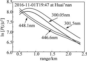
2016-11-01T19:47~20:36利用该激光雷达对安徽淮南大气研究院内的大气进行了水平观测实验。图 2中给出了2016-11-01T19:47,测污激光雷达测量的大气水平后向散射回波信号ln[P(z)z2]和距离z的关系曲线。从图 2中可以看出,在0.8km到2.4km的范围内, ln[P(z)z2]与z呈现很好的线性关系。由于300.05nm和448.1nm分别对应二氧化硫和二氧化氮的强吸收线,为了尽量减小二氧化氮和二氧化硫的影响,因此选择301.5nm和446.6nm来反演水平的大气消光系数。从图 3中的拟合曲线可以看出,在0.8km~ 2.4km的范围内, ln[P(z)z2]与z呈现很好的线性关系,拟合直线斜率的一半即为301.5nm和446.6nm波长对应的大气水平消光系数α301.5=0.520km-1和α446.6=0.383km-1。通过计算得到301.5nm和446.6nm两波长对应的大气水平能见度Rv分别为16.47km和13.39km。
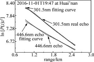
Figure 3. The fitting curve of echo signal ln[P(z)z2] and distance z of atmospheric horizontal at 301.5nm and 446.6nm
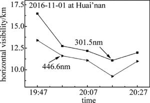
图 4中给出了2016-11-01T19:47~20:36用该激光雷达所测量的数据计算出的301.5nm和446.6nm两个波长对应的大气水平能见度。从图中可以看出,随着大气的波动,虽然两个波长对应的大气水平能见度变化幅度不一样,但是两个波长对应的大气水平能见度在一定程度上保持一致性。根据当时气象站发布的19:00和20:00两个时刻能见度分别为14.8km和11.4km,说明反演结果的准确性,本文中所介绍的激光雷达能够实时监测能见度的变化。
-
2016-11-01T21:10~22:20利用该激光雷达对安徽淮南大气研究院内的大气进行了垂直观测实验。图 5a为根据21:10~22:20所得数据反演出的301.5nm波长气溶胶的垂直消光系数廓线,图 5b为根据21:10~22:20所得数据反演出的446.6nm波长气溶胶的垂直消光系数廓线。从图中可以看出,随时间的变化,301.5nm和446.6nm分别反演出的气溶胶垂直消光廓线变化趋势基本一致,说明这段时间3km以下大气趋于平稳。另外,对于同一时刻,301.5nm和446.6nm相对应的气溶胶垂直消光廓线变化趋势也基本相同,说明反演出的数据比较准确。图 5c为根据21:10~22:20所得数据算出的Ångström指数,从图中可以看出Ångström指数随着时间的推移有所变化,但其空间变化趋势相同。
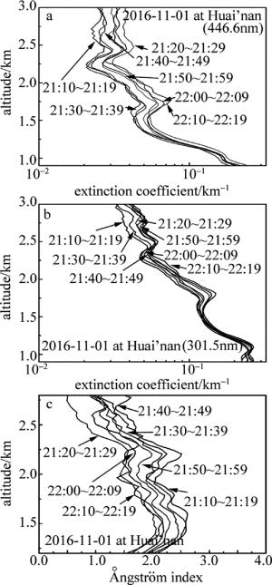
Figure 5. Spatial and temporal distribution of aerosol extinction profile and corresponding Ångström index
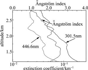
图 6为2016-11-01T21:10所得数据反演出的301.5nm和446.6nm波长的气溶胶消光系数和对应的Ångström指数。从图中可以看出,两波长的消光系数趋势基本一致,用两波长算出来的Ångström指数在1.2km~2.8km的范围内波动较大,从1.2km~1.5km之间Ångström指数逐渐增大,气溶胶粒子半径逐渐减小,从1.5km~2.3km之间Ångström指数比较稳定在2附近波动,气溶胶粒子半径在这一段区间内比较稳定。从2.3km~2.8km之间Ångström指数逐渐减小,气溶胶粒子变大,可能有两个因素造成的,首先由于3km以下左右的近地面层,受人为源和自然源影响最大,以及风的影响,活跃的对流层会使得部分气溶胶粒子向更远的高度蔓延,另外随着高度增加,激光雷达的回波信号信噪比减小,而Ångström指数对于信噪比比较敏感,在高处会存在一定的误差。
-
利用中国科学院安徽光学精密机械研究所研制的污染气体探测激光雷达回波数据,以斜率法反演了301.5nm和446.6nm在水平方向上的大气消光系数及能见度,以Fernald方法反演了301.5nm和446.6nm在垂直方向上的气溶胶消光系数和Ångström指数。结果表明,水平方向上,301.5nm和446.6nm的大气消光系数和能见度随时间变化均保持一致性;垂直方向上,301.5nm和446.6nm气溶胶消光系数随时空变化趋势相同,Ångström指数随着时间的推移有所变化,但空间变化趋势相同。在接下来的工作中需要将O3对气溶胶消光系数的影响考虑进去,更准确地反演出气溶胶消光系数和Ångström指数的分布,进一步可以修正气溶胶对反演SO2和NO2的影响。
测污激光雷达探测气溶胶消光特性和Ångström指数
Detection of aerosol extinction characteristics and Ångström index by monitoring pollutants lidar
-
摘要: 为了研究测污激光雷达对水平能见度和垂直气溶胶消光系数变化趋势的探测,采用污染气体探测激光雷达,以斜率法和Fernald方法,反演了301.5nm和446.6nm在水平及垂直方向的消光系数,以及波长的Ångström指数。结果表明,水平方向上,301.5nm和446.6nm的消光系数和能见度随时间变化均保持一致性;垂直方向上,301.5nm和446.6nm气溶胶消光系数随时空变化趋势相同,Ångström指数随着时间的推移有所变化,但空间变化趋势相同。该结果对分析差分吸收激光雷达修正气溶胶的影响是有所帮助的。
-
关键词:
- 激光技术 /
- 气溶胶消光系数 /
- 激光雷达 /
- Ångström指数
Abstract: In order to study the detection of horizontal visibility and vertical aerosol extinction coefficient by monitoring pollutants lidar, the extinction coefficients of 301.5nm and 446.6nm in horizontal and vertical directions and wavelength Ångström index were retrieved by the slope method and the Fernald method. The result shows that, in the horizontal direction, the extinction coefficients and visibility of 301.5nm and 446.6nm vary with time consistently. In the vertical direction, the extinction coefficients of 301.5nm and 446.6nm follow the same trend in time and space. The Ångström index has changed with the change of time. But the spatial change trend is the same. The results are helpful to correct the effect of analytical differential absorption lidar on aerosol.-
Key words:
- laser technique /
- extinction coefficient of aerosol /
- lidar /
- Ångström index
-
Table 1. Specification of monitoring pollutants lidar
transmitter(SO2) waelength 300.05nm(on), 301.5nm(off) laser class USA continum 8010 Nd:YAG laser(532nm) pump, Germany radiant dye laser(600.1nm, 603nm) repetition 10Hz energy 8mJ transmitter(NO2) waelength/nm 448.1nm(on), 446.6nm(off) laser class USA continum 8010 Nd:YAG laser(355nm) pump, Germany radiant dye laser(446.6nm, 448.1nm) repetition 10Hz energy 5mJ receiver telescope near newtonian,focus length 750mm,diameter 350mm,field of view 0.2mrad~2mrad optical filter central wavelength 300.75nm, band width 3.0nm(SO2), block OD5(200nm~1100nm), Φ=25.4mm; central wavelength 447.50nm, band width 3.0nm(NO2), block OD5(200nm ~1100nm), Φ=25.4mm detector (PMT) 9142QB,Φ=25mm,185mm~650mm, rise time <50ns,gains 105~106,voltage 750V~1200V A/D PCI-9826H, 20MS/s,channel number 4(16bit) Table 2. Molecular extinction coefficient of three kinds of atmospheric pollutants at the corresponding wavelength
pollutant NO2 SO2 O3 waelength/nm 301.5 446.6 301.5 301.5 N(z)σ(λ0)/km-1 0.014 0.043 0.025 0.034 -
[1] ZHANG Ch G, ZHANG Y J, HAN D W, et al. Monitoring for the particlesemitted by vehicle with lidar[J]. Laser Technology, 2009, 33(2):130-133(in Chinese). [2] YAN Sh Sh, LI H H. Determination of geometrical form factor of a lidar by means of Raman-Mie method[J]. Laser Technology, 2013, 37(4):511-514(in Chinese). [3] CHI R L, WU D Ch, LIU B, et al. Dual-wavelength mie lidar for measuring the whole tropospheric aerosols[J]. Journal of Atmospheric and Environmental Optics, 2008, 3(3):179-186(in Chinese). [4] MAO M J, WU Y H, QI F D, et al. Mobile dual-wavelength mie lidar[J]. High Power Laser and Particle Beams, 2005, 17(5):677-680(in chinese). [5] WANG Q M, ZHANG Y M. Development of meteorological lidar[J]. Meteorological Science and Technology, 2006, 34(3):246-249(in Chinese). [6] ZHOU J, YUE G M, JIN Ch J, et al. Two-wavelength mie lidar for monitoring of tropospheric aerosol[J]. Acta Optica Sinica, 2000, 20(10):1412-1417(in Chinese). [7] LIU J, HUA D X, LI Y, et al. Design of a compact Mie lidar system[J]. Journal of Xi'an University of Technology, 2007, 23(1):1-5(in Chinese). [8] IWASAKA Y, HAYASHIDA S. The effects of the volcanic eruption of St. Helens on the polarization properties of stratospheric aerosols-lidar measurement at Nagoya[J]. Journal of the Meteorological Society of Japan, 1981, 59(4):611-614. doi: 10.2151/jmsj1965.59.4_611 [9] LIU D, QI F D, JIN Ch J, et al. Polarization lidar observations of cirrus clouds and asian dust aerosols over Hefei[J]. Chinese Journal of Atmospheric Sciences, 2003, 27(6):1093-1100(in Chinese). [10] CHI R L, WU D Ch, LIU B, et al. Dual-wavelength Mie lidar observations of tropospheric aerosols spectroscopy and spectral analysis[J]. Spectroscopy and Spectral Analysis, 2009, 29(6):1468-1472(in Chinese). [11] DI H G, HOU X L, ZHAO H, et al. Detrctions and analyses of aerosol optical properties under different weather conditions using multi-wavelength mie lidar[J]. Acta Physics Sinica, 2014, 63(24):248-255(in Chinese). [12] HUANG J, HU Sh X, CAO K F, et al.Design of three dimensional scanning control system for air pollution monitoring Lidar based on LabVIEW[J].Journal of Atmospheric and Environmental Optics, 2013, 8(2):124-129(in Chinese). [13] LIN J M, CAO K F, HU Sh X, et al. The experiment study of SO2 measurement by differential absorption lidar[J]. Infrared and Laser Engineering, 2015, 44(3):872-879(in Chinese). [14] LIU Q W, WANG X B, CHEN Y F, et al. Detection of atmospheric NO2 concentration by differential absorption lidar based on dye lasers[J]. Acta Optica Sinica, 2017, 37(4):338-345(in Chinese). [15] CHEN M, SUN D S, LI H J, et al. Detective method and analysis of atmospheric slant visibility for lidar[J]. Infrared and Laser Engineering, 2006, 35(2):156-160(in Chinese). [16] FERNALD F G. Analysis of atmospheric lidar observation[J].App-lied Optics, 1984, 23(5):652-653. [17] ZHANG Zh Y, SU L, CHEN L F. Retrieval and analysis of aerosol lidar ratio at several typical regions in China[J]. Chinese Journal of Lasers, 2013, 40(5):513002(in Chinese). doi: 10.3788/CJL -


 网站地图
网站地图

 下载:
下载:
