-
微型投影技术是一种新型的现代投影显示技术,它凭借自身的小型化、便捷化而逐步渗入到人们的日常生活中,在当今飞速发展的信息化年代越来越受到人们的青睐,成为投影显示的一大发展潮流。作为一种新兴固态光源,发光二极管(light-emitting diode, LED)具有体积小、寿命长、亮度高、色域广等特点[1-6];结合数字光处理系统(digital light processing, DLP)投影具有高对比度、高分辨率的特点,实现小型化的便携式微型投影,满足人们对投影显示随身化的需求。
在投影显示领域,DLP技术由美国德州仪器公司开发,核心器件是数字微镜元件(digital micromirror device, DMD)[7]。基于DLP投影原理,人们进行了大量的科学研究,如ZHAO等人提出的一种针对个人用户使用的微型投影机光学引擎[8];CHEN等人研制出了一种具有较小视场的条纹投影系统[9];AN等人针对传统投影光栅相位法的光学三角法模型进行了改进,提出了一种新的光栅投影相位法系统模型及标定方法[10];然而现有投影仪的整机体积、光斑均匀性和光能利用率还有待提高,而这也是照明光学中的重要评价指标[11]。
传统单片式DLP投影系统具有一个照明光路和一个投影光路,包括光源、反光碗、色轮、导光管、中继透镜、反射镜、DMD、吸收体和投影透镜[12]。光源发出的光线经过椭圆反射器汇聚后,经过高速旋转的色轮分光,在任何一瞬间,白光经过色轮后,只有一种颜色的光透过,其它颜色的光被阻挡和吸收,透过的光线与导光管耦合入射到中继透镜上,经过中继透镜汇聚后入射到反射镜上,在反射镜表面改变一次光路方向后入射到DMD表面,DMD表面众多的微镜在±12°两个方向高速翻转,当微镜处于+12°时光线进入投影透镜,反之被吸收体吸收。这种传统的单片式投影系统的缺陷是:一方面,使用的元器件较多、结构复杂,体积较大,难以降低整机的体积,过多的元器件也导致了整机的电光转换效率低,不仅对光能的损耗较为严重,更主要的是损耗的光能使整个投影系统的温度升高,对整个投影系统的散热造成了一定的影响,同时,过多的元器件也导致了整机的成本较高; 另一方面,考虑到投影光斑均匀性的要求,光线经过中继透镜时难免会产生像差,对光源的均匀性也造成了一定的影响。
-
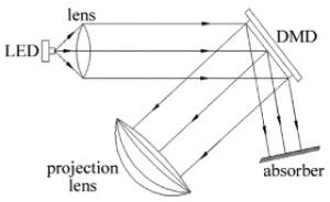
为了解决上述问题,本文中提出了一种基于LED和透镜的低成本微型投影系统光路设计,如图 1所示。包括光源、透镜、数字微镜元件、投影透镜、吸收体;投影系统中不含色轮、不含二向色镜、不含导光管。解决了现有的投影系统结构复杂、元器件较多、体积较大、成本较高、散热困难等问题,简化了投影系统的光学结构,缩小了整机的体积,降低了成本,提高了光能的利用率。
-
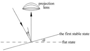
数字微镜元件由美国德州仪器公司于1987年发明,本质是一个反射式数字半导体光分布调制器,在CMOS存储芯片上构建数以百万计的微反射镜面,DMD通过精确控制每个微镜的偏转角度来实现图像成像,生成动态图像信息[13]。在没有通电时,数字微镜上所有的反射镜都静止在平衡位置,该位置称为平板状态,数字微镜元件通电后每个反射镜都可以绕着自己的转轴旋转,每个反射镜至少有两个稳定的工作状态。在第1个稳定的工作状态时,如图 2所示。反射镜的镜面与该反射镜平板状态时的镜面的夹角为θ,在本文中设计的光路中,反射镜处于第一稳定状态下,大部分入射到反射镜上的光线在反射镜上的入射角接近于反射镜相对其自身平板状态的角度,大部分被反射镜反射的光线的方向几乎垂直于平板状态,并被投影透镜接收后投射到屏幕上,经过屏幕漫反射以后进入用户眼中,用户看到清晰的图像。
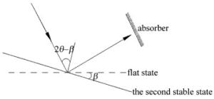
在反射镜处于第2个稳定的工作状态时,如图 3所示。反射镜的镜面与该反射镜平板状态时的镜面的夹角为β,绝大部分被反射镜反射的光线不能进入投影透镜,而是被吸收体所吸收,大部分入射到反射镜上的光线在反射镜上的入射角接近于2θ-β。
LED光源发出的光线经过透镜后,入射到数字微镜表面,数字微镜元件反射的光线近似是平行光,在保证LED发出的光线不被遮挡的前提条件下,数字微镜元件不需要在投影透镜的物平面附近,数字微镜元件和投影透镜之间的距离可以任意设置,屏幕到投影透镜之间的距离可以在较大范围内自由设定。
为了保证投影仪的体积小巧,选择了TI公司的DLP5500型号的DMD芯片,该芯片的分辨率为1024pixel× 768pixel,封装尺寸为22.30mm×32.20mm,具体的参量如表 1所示。
Table 1. DMD chip of DLP5500 type
chip size 0.55inch(1inch=2.54cm) micromirror pitch 10.8μm length to width 11.059mm×8.294mm(4:3) tilt angle ±12° reflectivity 88% broadband visible light 420nm~700nm -
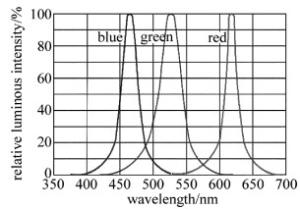
三色LED可以同时发出红、绿、蓝3种颜色的光线,可以满足投影仪照明的需要。选用CREE公司的CLMVB-FKA型号的LED灯珠。该灯珠的相对发光强度光谱图如图 4所示。与选用的DMD芯片表面宽带波长匹配。发光强度为:红(224mcd~450mcd)@ 20mA;绿(180mcd~450mcd)@10mA;蓝(56mcd~ 140mcd)@ 10mA。该LED的封装尺寸为2mm×2mm× 0.9mm,非常适合微型投影仪的光路设计。
-
为了满足LED发出的光线经过透镜后完全的入射到数字微镜的表面,选用了YJM-Ø18mm光学玻璃凸透镜,该透镜的具体参量如表 2所示。透镜的内径是16mm,数字微镜元件阵列的对角线长度是13.8mm,保证了经过透镜后的光线可以入射到数字微镜的整个表面。该透镜的焦距f=14.5mm,光源在透镜的光轴上,与透镜之间的距离为f,确保LED光源发出的光线经过透镜后,平行于透镜的主轴入射到数字微镜表面。
Table 2. Specific parameters of lens
outside diameter 18mm inside diameter 16mm height 7mm thick side 2mm focal length 14.5mm -
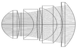
考虑到投影仪本身的体积紧凑以及与DMD的尺寸匹配,在镜头库中选择了一组五片式的投影镜头,有4个球面透镜和1个非球面透镜,其中镜头的入瞳直径为20.8mm。如图 5所示,得到ZEMAX软件进行仿真的光线追迹图。
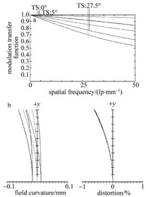
为了降低成本,球面透镜材料为普通玻璃,非球面透镜材料为有机玻璃(polymethyl methacrylate, PMMA),有效地控制了成本。结合ZEMAX软件,修改镜头的焦距、工作距离、视场角等参量,达到:(1)镜头的视场角控制在60°左右;(2)在50lp/mm处,镜头的调制传递函数(modulation transfer function, MTF)值大于0.5;(3)畸变小于1%。利用ZEMAX软件进行优化,优化结果如图 6所示,图中TS代表子午弧矢(tangential sagittal)。
根据投影镜头的技术指标以及投影镜头的具体参量,对镜头库中选中的模型进行优化,对镜头的视场角、焦距、工作距离进行了限制。利用ZEMAX软件优化后该投影镜头的焦距为14.6mm,镜头的入瞳直径为20.2mm,镜头的总长度为76.8mm,视场角为50°,具体的镜头系统结构参量如表 3所示,表中, ri为曲率半径,di为系统前后组之间主面的间隔。从优化结果的调制传递函数曲线中明显可以看出,在50lp/mm处,镜头的MTF值大于0.5,从畸变图可以看出,镜头的畸变小于1%,因此优化的结果达到了预期的目标。
Table 3. Optical parameters of lens
i ri/mm di/mm material 1 39.93 1.86 PMMA 2 8.268 14.54 3 57.683 1.63 H-LAF3A 4 18.809 4.27 5 20.867 13.16 ZF7L 6 -87.862 3.33 7 infinity 6.95 8 -22.955 1.21 ZF7L 9 16.444 7.00 H-LAK50A 10 -34.823 0.16 -
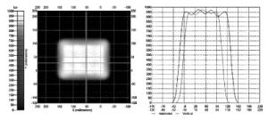
根据以上选择的模型和利用ZEMAX仿真得到的参量,在TRACEPRO软件中建立了一个3维模型,包括LED、透镜、DMD、投影镜头,整个光学系统的体积控制在76.8mm×32.2mm×25mm。使用厂家提供的LED模型,透镜和DMD也严格按照厂家标准设置尺寸、焦距、反射率、折射率;投影镜头按照ZEMAX软件优化后导入到TRACEPRO软件中。追迹300万条光线,得到照度图如图 7所示。
根据美国国家标准协会规定的9点照度均匀性公式[14]:
$ U = \left( {1 - \frac{{{E_{\max }} - {E_{{\rm{ave}}}}}}{{{E_{{\rm{ave}}}}}}} \right) \times 100\% $
(1) 式中,U代表均匀性,Emax是9个取样点的最大照度值,Eave是平均照度值。得到整个投影系统的照度均匀性为96.6%,满足了投影仪屏幕的照度均匀性要求。
投影距离为50cm~60cm,屏幕上至少需要光通量20lm,此时屏幕亮度与笔记本电脑的屏幕亮度基本相当[8]。在仿真过程中,将屏幕设置在距离投影镜头0.5m的位置,根据TRACEPRO软件追迹的光线结果,得到各个光学软件的光能利用率和表面光通量,如表 4所示。光能的利用率为60.1%,屏幕的光通量为21.7lm。
Table 4. Analysis of ray tracing results
light energy utilization/% luminous flux/lm LED 81.5 36 lens 93.5 29.3 DMD 88.0 27.4 projection lens 89.6 24.1 screen 60.1 21.7 -
提出了一种结构简单、体积紧凑的微型投影系统,目的是为了携带方便、节约成本, 满足个人用户使用需求。选用了特定的LED灯珠、透镜、DMD,单颗三色LED发出的光线经过透镜后直接形成平行光,入射到DMD的表面,整个光学系统的体积控制在76.8mm×32.2mm×25mm。利用ZEMAX软件对投影镜头进行了优化,将整个光路元器件导入到TRACEPRO软件中,进行光线追迹和结果分析。结果表明, 整个投影系统的光能利用率为60.1%,照度均匀性为96.9%,距离投影镜头0.5m处,屏幕表面的光通量为21.7lm,符合微型投影仪的设计指标。该设计方案大大简化了光学结构,减小了整机的体积,降低了成本,解决了后续的微型投影系统的设计难题,具有一定的市场前景。
微型投影系统光路设计
Design of optical path for miniature projection systems
-
摘要: 为了改善传统的数字光处理投影系统(DLP)体积较大、结构复杂、成本较高、对光源的利用效率较低的问题,采用一种基于单颗三色发光二极管作为照明光源,单颗透镜形成平行光的新型DLP投影光路结构的方法,对传统光路进行了改进与优化。无需传统光路中的色轮,透镜直接实现了传统投影光路中聚光和匀光的复杂结构,并利用TRACEPRO软件进行建模,通过光线追迹对该投影光路进行了光学分析。结果表明,整个光学系统的体积控制在76.8mm×32.2mm×25mm,光能利用率达到了60.1%,光斑均匀性达到了96.6%,屏幕表面的光通量为21.7lm。该研究减小了投影光路体积,简化了光学结构,提高了光能利用率。Abstract: In order to improve the problems of traditional digital light processing (DLP) projection system, such as, large volume, complex structure, high cost, and low utilization efficiency of light source, using single three-color light emitting diode as light source and using a novel DLP projection optical structure of forming parallel light by a single lens, the traditional optical path was improved and optimized. Without colorwheel in the traditional optical path, the complex structures of light gathering and light distribution in the traditional projection light path were realized by lens directly.After using TRACEPRO software to model, the projection light path was analyzed by ray tracing. The results show that, the volume of whole optical system is controlled at 76.8mm×32.2mm×25mm, utilization rate of light energy reaches 60.1%, spot uniformity reaches 96.6%, and luminous flux on screen surface is 21.7lm. The research reduces the volume of projection light path, simplifies the optical structure and improves the utilization ratio of light energy.
-
Key words:
- optical design /
- projector /
- light-emitting diode /
- lens
-
Table 1. DMD chip of DLP5500 type
chip size 0.55inch(1inch=2.54cm) micromirror pitch 10.8μm length to width 11.059mm×8.294mm(4:3) tilt angle ±12° reflectivity 88% broadband visible light 420nm~700nm Table 2. Specific parameters of lens
outside diameter 18mm inside diameter 16mm height 7mm thick side 2mm focal length 14.5mm Table 3. Optical parameters of lens
i ri/mm di/mm material 1 39.93 1.86 PMMA 2 8.268 14.54 3 57.683 1.63 H-LAF3A 4 18.809 4.27 5 20.867 13.16 ZF7L 6 -87.862 3.33 7 infinity 6.95 8 -22.955 1.21 ZF7L 9 16.444 7.00 H-LAK50A 10 -34.823 0.16 Table 4. Analysis of ray tracing results
light energy utilization/% luminous flux/lm LED 81.5 36 lens 93.5 29.3 DMD 88.0 27.4 projection lens 89.6 24.1 screen 60.1 21.7 -
[1] JIANG X M, ZHU X Y, LIU T, et al. Design and implementation of LED indoor visible lightvoice communication system[J]. Laser Technology, 2014, 38(6):807-812(in Chinese). [2] CHANG F, SUN Zh Y, WANG R G, et al. Improvement method of non-uniformity correction of LED display image[J]. Optics and Precision Engineering, 2011, 19(4):929-937(in Chinese). doi: 10.3788/OPE. [3] LIANG H J, DENG J, WANG G, et al. Design and application of synchronous trigger light sources for high-speed photography[J]. Laser Technology, 2016, 40(3):331-334(in Chinese). [4] ZHOU Q Ch, BAI Z L, LU L, et al.Remote phosphor technology for white LED applications:advances and prospects[J]. Chinese Optics, 2015, 8(3):313-328(in Chinese). doi: 10.3788/co. [5] FENG Q B, LI Y N, LI Q G, et al. Design of free-form surface lens based on light-emitting diode light distribution curve[J]. Optics and Precision Engineering, 2016, 24(8):1884-1893(in Chinese). doi: 10.3788/OPE. [6] LIU Q, LIU Q N. Divergence characteristics of light spot of a circular LED array[J]. Laser Technology, 2015, 39(6):858-862(in Ch-inese). [7] WANG Ch, HAO W L, TIAN L W, et al. Design of miniature DLP projective optical path based on new type light guide tube[J].Infrared and Laser Engineering, 2015, 44(8):2472-2477(in Chinese). [8] ZHAO X, FANG Zh L, CUI J Ch, et al. Research on micro-projector optical Engine[J].Acta Optical Sinica, 2007, 27(5):913-918(in Chinese). [9] CHEN Ch, YU Y Q, HUANG Sh J, et al. 3-D small-field imaging system[J]. Infrared and Laser Engineering, 2016, 45(8):0824002(in Chinese). doi: 10.3788/IRLA [10] AN D, CHENG L, DING Y F, et al. Optical system model and calibration ofgrating projection phase method[J]. Chinese Optics, 2015, 8(2):248-254(in Chinese). doi: 10.3788/co. [11] HOU Y. Design of lens to realize small angle lighting for LED[J]. Infrared and Laser Engineering, 2016, 45(5):0518004(in Ch-inese). doi: 10.3788/irla [12] GÜNTHER A. Optical concept for an active headlamp with a DMD array[J].Proceedings of the SPIE, 2008, 7003:70032D. doi: 10.1117/12.782071 [13] LI Zh, MOU D, LÜ Sh L, et al. Design of zoom LWIR projection system based on DMD[J].Infrared and Laser Engineering, 2016, 45(12):1218003(in Chinese). doi: 10.3788/IRLA [14] ZHEN Y, YE Z, YU F. Ultrahigh-performance lamp illumination system with compound parabolic retroreflector for a single liquid-crystal-on-silicon panel display[J]. Optical Engineering, 2007, 46(5):054001. doi: 10.1117/1.2736310 -


 网站地图
网站地图

 下载:
下载:
