-
激光熔覆技术是激光先进制造技术中最重要的支撑技术之一。该技术把快速原型制造技术和激光熔覆表面强化技术相结合,采用高能量激光在金属基体上形成熔池,将通过送粉装置和送粉喷嘴输送到熔池的合金粉末或预先置于基体上的涂层熔化,快速凝固后与基体形成冶金结合的表面涂层,也可以在金属基体上逐层堆积而成形为金属零件[1-3]。与传统的零件成形方法和其它表面工程技术相比,激光熔覆技术具有热变形小、熔覆层形状和性能可控等诸多优点,广泛应用于各种复杂零件的快速成形制造、增材修复和改性等方面。目前,随着再制造与增材制造产业的发展,激光熔覆技术在航空航天、汽车模具和武器等行业的制造与再制造领域也具有良好的应用前景[4-5]。
针对一些对表面修复质量要求越来越高的大型工件,如大型船舶齿轮曲轴、汽车车身模具、大型武器装备等零件表面的修复场合,传统小光斑的激光熔覆设备由于制造效率问题变得不再适用,而利用大功率宽带激光设备,其扫描一次的面积能增加10倍到几十倍,可以大大提高激光熔覆的修复制造效率。同时,由于显著地减少了搭接次数,使得熔覆层的质量也相应得到提高[6]。但由此带来的问题是,激光熔覆过程中合金粉末如何准确均匀地输送到激光熔覆产生的熔池中。目前,国内外设计应用的同轴送粉喷嘴多适用于圆形小光斑的多路环向或孔式送粉[7-9],而对于大宽带矩形光斑的激光熔覆送粉喷嘴的设计较少,主要以侧向宽带送粉为主[10-11]。由于宽带同轴送粉在设计与制造工艺上存在较大困难,因此较少有机构对此进行开发。苏州大学LEI等人开发了一款激光宽带熔覆光内送粉装置[12],通过光路转换,将激光束分为左右两束,粉束从中间竖直送入熔池。浙江工业大学HU等人设计了一款可调式侧向送粉装置,结构简单易行,但粉末利用率很低[13-14],同时侧向送粉存在熔覆质量方向不一致的问题。为了实现粉末以矩形形式高效地送入熔池,提高粉末利用率,QIN等人设计了一款宽带激光熔覆用同轴送粉喷嘴装置,该喷嘴装置在实心宽带激光束的两侧,同步地以矩形出口的形式将狭长形的粉束送进熔池[15]。作者利用FLUENT软件中的气固耦合离散相模型,分析宽带激光熔覆同轴送粉喷嘴的送粉道在不同倾角和不同出口间隙条件下的粉末汇聚特性,以及外层保护气速度对粉末汇聚性的影响,为宽带激光熔覆用同轴送粉喷嘴装置的设计提供参考依据,并采用所选参量方案,设计出宽带激光熔覆用同轴送粉喷嘴装置,通过送粉与熔覆实验验证了送粉喷嘴的合理性。
-
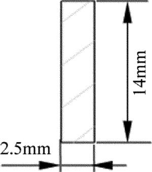
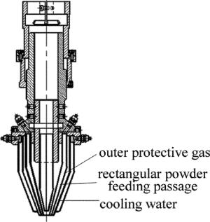
图 1为一般的激光熔覆同轴送粉喷嘴结构示意图,主要由送粉道、保护气道和激光束通道构成[7]。作者所设计的送粉喷嘴适用于大功率半导体激光器,激光束为矩形光斑,其形状如图 2所示,尺寸为2.5mm×14mm。因此,在设计喷嘴时,必须为激光束预留足够的空间,以免将喷嘴烧坏,并且要求粉束汇聚形式与光斑相适应。
根据结构要求,初步设计出该喷嘴的结构图,如图 3所示。该喷嘴装置采用同轴送粉方式实现对宽带激光熔覆的送粉。与目前大部分机构所设计的环形或孔式同轴送粉所不同的是,该送粉喷嘴的送粉通道为与激光光斑相适应的矩形流道。所设计的内层保护气与激光通道为同一通道,能够在加工过程中形成惰性气体氛围,防止熔覆层氧化。外层保护气主要用于对粉束的扩散抑制作用,从而对粉斑进行整形,使得粉斑汇聚更加均匀[15]。
-
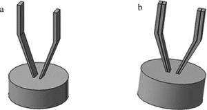
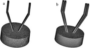
根据参考文献[16]中的分析可知,送粉通道采用收缩出口时,载气气体和粉末不断被压缩,气流和粒子加速,粒子所受到气流的拽力增大,使得粉末在出口处的发散角更小,其粉末汇聚特性远远好于平行出口。因此所设计的送粉通道采用收缩出口的形式。为了对喷嘴进行分析,需要对结构图进行物理模型的简化,将最主要部分的粉道和气道单独提出来进行分析。图 4为简化的单粉道和气-粉通道3维流场模型。送粉喷嘴的下方为大气流场计算域,其尺寸相对于粉末出口足够大。对所建的模型进行网格划分,见图 5。
为了研究送粉喷嘴的粉末汇聚特性,针对送粉道在不同倾角和不同出口间隙的条件下,利用FLUENT软件分析其对粉末汇聚宽度和汇聚焦距的影响,如图 6所示。根据实践经验,送粉通道的倾角α不宜小于60°[16],因而倾角α分别选取60°, 65°, 70°和75°进行分析。对于出口间隙δ的取值,假设不考虑重力、气流和压强等影响,粉末从粉道喷出后均匀分布且粉末无发散现象时,粉末在焦点处的聚焦范围为Δ。设计时,Δ取值应尽量靠近激光宽带的宽度2.5mm,根据结构尺寸,通过纯几何计算分析,出口间隙δ应在3mm左右,因而出口间隙δ分别选取2.5mm, 3.0mm, 3.5mm。送粉道倾角α和出口间隙δ的取值如表 1所示,各组组合编号如表 2所示。
Table 1. Values of feeding angle and exit gap
angle α/(°) 60 65 70 75 exit gap δ/mm 2.5 3.0 3.5 Table 2. Numbers of each group
α /(°) 60 65 70 75 δ/mm 2.5 3.0 3.5 2.5 3.0 3.5 2.5 3.0 3.5 2.5 3.0 3.5 number D11 D12 D13 D21 D22 D23 D31 D32 D33 D41 D42 D43 -
将应用FLUENT软件对离散相模型的多相流工况进行数值模拟,分析同轴送粉喷嘴的粉末汇聚特性。在FLUENT软件中,当颗粒相的体积分数小于0.10时,可以把颗粒作为离散相处理;当颗粒相体积分数大于0.10时,颗粒按连续相处理,此时为多相流模型[17]。在本文研究的离散相模型中,粒子被看成是一个个离散的颗粒,首先计算连续相的流场,再打开离散相模型,结合连续相流场和相应物理模型来对每一个离散的颗粒进行求解,进而计算得到每一个颗粒的轨迹和速度。本文中运用标准k-ε(k为紊流脉动动能,ε为紊流脉动动能的耗散率)湍流模型对气相进行求解,而离散相的求解在气相的基础上,通过所建立的随机粒子轨道模型、结合气相流场分布求解粒子运动学方程来获得。为简化计算模型,须做如下假设[18-19]:(1)颗粒运动是稳态的,气、粉具有相同的速度流场;(2)忽略激光的热辐射影响;(3)只考虑影响较大的惯性力和重力,忽略附加质量力、升力等;(4)不考虑颗粒之间的碰撞和粘性作用。
然后在injection中添加离散相的两个入口,分别为power inlet 01和power inlet 02,设置粒子的直径、流量、速度等参量即可。各相材料在fluent database中进行加载,调用相应的材料。其中气体相为氩气,粒子相为镍粉,各边界power inlet 01, power inlet 02, wall, up, sides, down分别设置边界物理条件为velocity inlet, velocity inlet, wall(reflect), pressure outlet, pressure outlet, wall(trap)。
-
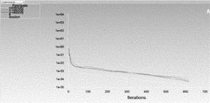
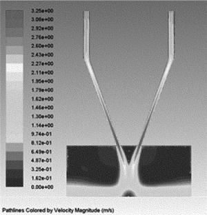
实际中的粉末由送粉器在载气气体的带动下进行输送,故假设在喷嘴入口处粉末粒子的速度与载气气体的速度分布相同,且速度的方向垂直于入口平面[13]。设置载气速率为1.5 m/s,离散相粉末的速率为1.5m/s,送粉量为8×10-4kg/s、平均粒径取为9×10-5m,各监视变量的迭代残差值小于10-6且计算追踪到的粒子进出口流量稳定,可认为整个计算过程收敛,计算收敛曲线如图 7所示。图 8为气体速度分布图。
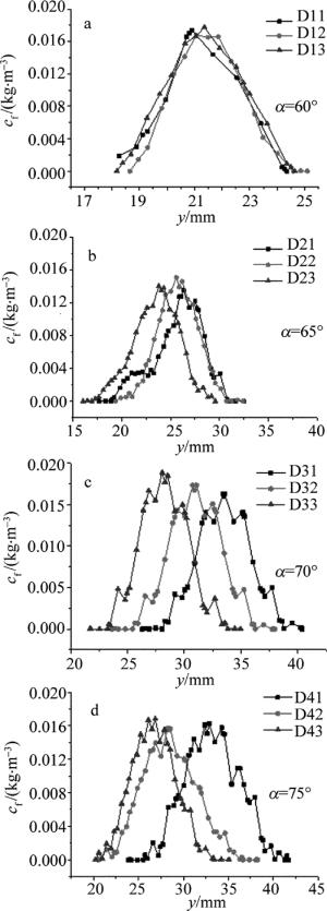
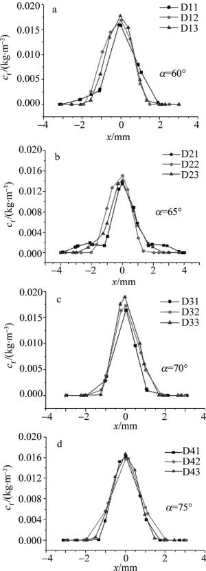
粉末浓度分布的计算机的仿真结果如图 9和图 10所示。图中y方向为以喷嘴出口为原点的沿轴线距离,x方向为以喷嘴对称平面上粉末最大浓度点为原点与左右两侧的距离[18]。可见,x, y方向上的浓度分布均近似服从高斯分布。由图 9可知,在y方向上,出口间隙δ对汇聚点的最大浓度影响不大,其最大浓度点的各浓度差均在6%以内。另外,随着倾角α的增大,出口间隙δ对焦距的影响也越来越大,且δ越小,焦距越大。由图 10可知,出口间隙δ越大,浓度越高,且当倾角为70°时,汇聚点的浓度cf最高。
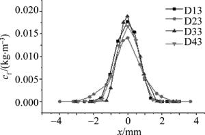
在x方向上,将粉末浓度值降低到汇聚点最大浓度值的1/e2时所对应的距离定义为粉末汇聚直径[20-21]。表 3为倾角为70°时的汇聚直径对比。由表 3可知,倾角为α=70°时,出口间隙为3.5mm时的汇聚直径小于激光宽度2.5mm,且较为接近2.5mm,粉末利用率较高。图 11为δ=3.5mm时不同倾角下x方向上的粉末浓度分布。由图可知,倾角为α=70°时的粉末浓度最大,汇聚点浓度cf=0.01882kg/m3。综上综合对比,选择D33作为最终设计结果。
Table 3. Powder convergent diameter while α=70°
number exit gap δ/mm convergent diameter/mm D31 2.5 2.2294 D32 3 2.5410 D33 3.5 2.4291 -
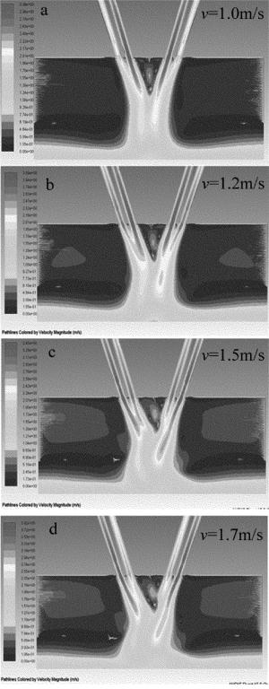
取外层保护气速率v分别为1.0m/s, 1.2m/s, 1.5m/s, 1.7m/s进行分析,分析结果如图 12所示。对比图 12a~图 12d,随着保护气速度的增大,载气气流会流向外层保护气气流方向的一侧,根据伯努利效应,流体的流速越大,压强越小,流体的流速越小,压强越大。当外层保护气速率过小时,无法起到对粉末的整形约束作用[22]。而当外层保护气速率过大时,则保护气气流会对载气气流产生影响,在伯努利效应作用下,使粉末向外扩散,不利于粉末的汇聚。综合分析考虑,选取v=1.0m/s作为外层保护气的速率参量。
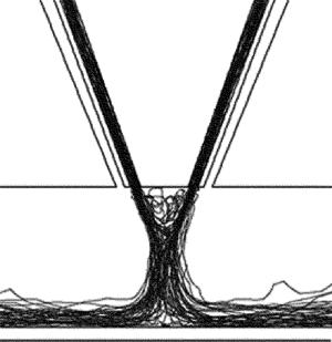
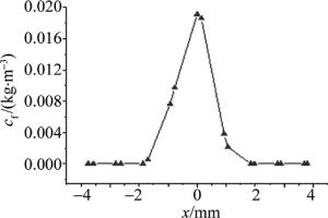
图 13和图 14分别为外层保护气速率v=1.0m/s时粉末粒子的轨迹图和x方向上的粉末浓度分布情况。由图可知,汇聚点浓度cf=0.01913kg/m3,粉末汇聚直径为2.4915mm,较无保护气时最高浓度有所提升,且提高了粉末利用率。
-
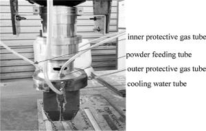
根据上述模拟分析,采用α=70°,δ=3.5mm设计制造同轴送粉喷嘴,考虑到激光熔池热辐射的影响,前端送粉头采用紫铜材料,能快速地将送粉喷嘴前端热量向外扩散,提高送粉喷嘴的工作稳定性, 上部连接与调节机构采用铝合金以减小整体质量, 将送粉喷嘴与送粉器、水泵、高纯氩气瓶相连。图 15为宽带激光熔覆同轴送粉喷嘴的实物图。
-
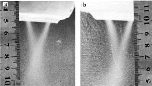
实验中利用高纯氩气作为载气和保护气体,采用镍基合金粉末,粉末直径范围为70μm~120μm,送粉流量为0.8g/s,载气速率为1.5m/s,保护气速率为1.0m/s,粉末汇聚效果如图 16所示。图 16a为无外层保护气时的粉束形态,图 16b为有外层保护气时的粉束形态。
从图 16可以看出,对称式粉末流从出口射出后,成一矩形形式在喷嘴下方汇聚,无外层保护气时的汇聚点距喷嘴出口约26mm,有外层保护气时的汇聚点距喷嘴出口约28mm,有外层保护气较无外层保护气气时的粉末发散稍小,粉末汇聚点的距离增大[23]。
-
采用德国某公司的3kW高功率半导体激光器系统进行单道熔覆实验。光路经整形透镜转换后光斑尺寸为14mm×2.5mm,保护镜镜头距激光光斑焦点330mm。根据上述参量,设定激光功率2.4kW,在45#钢基材上分别进行铺粉、侧向送粉和同轴送粉(有内层保护气)的单道熔覆实验(送粉时机器人扫描速率为4mm/s),实验结果如图 17所示。由图 17b可知,侧向送粉表面粘粉较多,同时熔覆层表面氧化较严重,粉末利用率低,飞溅严重。对比图 17c和图 17b可知,内层保护气可明显减小熔池熔渣的飞溅和改善表面氧化,熔覆层厚度比侧向送粉厚,提高了粉末利用率,但还有部分的粘粉和氧化问题。由图 17d可知,同轴有外层保护气送粉的表面熔覆质量接近铺粉的表面质量,内外双重保护气有效解决了氧化和粘粉问题,降低熔池熔渣的飞溅,宽带激光熔覆表面质量达到了预期要求。
-
(1) 根据宽带激光熔覆的激光光斑特点与设计要求,设计除了与之相适应的同轴送粉喷嘴装置。
(2) 采用FLUENT软件的离散相模型,重点分析了激光同轴送粉喷嘴粉送粉道在α为60°, 65°, 70°, 75°这4种倾角下的粉末分布情况。由数值分析可知,粉末浓度在x, y方向上均近似服从高斯分布。随着倾角α的增大,出口间隙δ对焦距的影响也越来越大,且δ越小,焦距越大。当倾角α=70°时,汇聚点浓度最高; 当倾角α=70°、出口间隙δ=3.5mm时,粉末的汇聚直径为2.429mm,略小于激光带宽2.5mm,粉末利用率较高。
(3) 对保护气的速率分析结果表明,随着保护气速率的增大,载气气流会向保护气气流方向一侧,当保护气速率过小时,无法起到对粉末的整形约束作用。而当保护气速率相对于载气速度过大时,则保护气气流会对载气气流产生影响,使粉末流向外扩散,不利于粉末的汇聚。
(4) 实验表明,外层保护气能够有效地降低熔覆层表面的氧化作用、提高加工表面质量,有利于后续多层多道的实验研究。
宽带激光熔覆同轴送粉喷嘴的设计与数值模拟
Design and numerical simulation of broad coaxial powder feeding nozzles for laser cladding
-
摘要: 为了设计一种适用于大功率的宽带激光熔覆同轴送粉喷嘴,采用FLUENT软件中的离散相模型,对送粉喷嘴的送粉道在不同倾角和不同出口间隙条件下的粉末汇聚特性和浓度分布特性进行了研究。分析了其它条件不变时,外层保护气流速对粉末汇聚的影响,得到了较优的结构尺寸,并利用设计研制的宽带同轴送粉喷嘴装置,进行了送粉和熔覆实验。结果表明,宽带激光同轴送粉喷嘴的焦点浓度在汇聚中心的径向和轴向都近似服从高斯分布;随着倾角的增大,出口间隙对焦距的影响也越来越大,且出口间隙越小,焦距越大;当倾角为70°; ,出口间隙为3.5mm时粉末汇聚性较好,粉末利用率较高;在其它条件不变时,外层保护气体流速过大或过小均不利于粉末汇聚,当外层保护气体流速略小于载气速率时,送粉喷嘴的粉末汇聚特性最佳。表面熔覆质量达到了预期要求,验证了该结构的合理性。所设计的宽带同轴送粉喷嘴对后续宽带激光熔覆的研究与应用具有重要意义。Abstract: In order to design a coaxial powder feeding nozzle for high power broad laser cladding, powder convergence property and concentration distribution for broad laser coaxial powder feeding nozzles were analyzed at different inclination angles and exit gap of the powder feeding channel by using the discrete phase model in FLUENT software. And when other conditions were fixed, the effect of outer protective gas velocity on powder convergence was analyzed and the better structure size was obtained. The experiments of powder feeding and cladding were carried out by using the designed and developed broad coaxial powder feeding nozzle. The experimental results show that, the focal point concentration of the coaxial powder nozzle is approximately obeyed by Gaussian distribution in radial direction and axial direction. With the increase of feeding angle, the effect of exit gap on focal length becomes more and more important.The smaller the exit gap, the greater the focal length. When feeding angle is 70° and exit gap is 3.5mm, powder convergence is better and utilization ratio of powder is high.When the other conditions are constant, the fact that outer protective gas velocity is too fast or too slow is not beneficial to powder convergence. When outer protective gas velocity is slightly less than carrying gas velocity, the characteristics of powder convergence of powder feeding nozzle is the best. The quality of surface cladding reaches the expected requirement, and the rationality of the structure is verified. The designed nozzle has a great significance for the research and application of subsequent broad laser cladding.
-
Table 1. Values of feeding angle and exit gap
angle α/(°) 60 65 70 75 exit gap δ/mm 2.5 3.0 3.5 Table 2. Numbers of each group
α /(°) 60 65 70 75 δ/mm 2.5 3.0 3.5 2.5 3.0 3.5 2.5 3.0 3.5 2.5 3.0 3.5 number D11 D12 D13 D21 D22 D23 D31 D32 D33 D41 D42 D43 Table 3. Powder convergent diameter while α=70°
number exit gap δ/mm convergent diameter/mm D31 2.5 2.2294 D32 3 2.5410 D33 3.5 2.4291 -
[1] ZHANG A F, LI D Ch, LU B H. Research progress in laser direct metal rapid prototyping technology[J]. Ordnance Material Science and Engineering, 2007, 30(5):68-72(in Chinese). [2] LU Q P, ZHANG A F, LI D Ch, et al. Numerical simulation and experimental research on gas-carrier coaxial powder nozzle[J]. Chinese Journal of Lasers, 2010, 37(12):3162-3167(in Chinese). doi: 10.3788/CJL [3] ZHANG D Y, WANG R Z, ZHAO J Zh, et al. Latest advance of laser direct manufacturing of metallic parts[J]. Chinese Journal of Lasers, 2010, 37(1):18-25(in Chinese). doi: 10.3788/JCL [4] SONG J L, LI Y T, DENG Q L, et al. Research progress of laser cladding forming technology[J]. Journal of Mechanical Engineering, 2010, 46(14):29-39(in Chinese). doi: 10.3901/JME.2010.14.029 [5] ZHONG M L, NING G Q, LIU W J. Fundamental aspects on laser rapid & flexible manufacturing of metallic components[J]. Applied Laser, 2011, 21(2):76-78(in Chinese). [6] SHI J J. Research on laser wide-band cladding device and process[D].Suzhou: Soochow University, 2007: 1-2(in Chinese). [7] XUE F, WANG Y M, LIU Sh Y. Research on coaxial powder feeding nozzle for laser cladding[J]. Machine Building & Automation, 2015, 44(3):46-49(in Chinese). [8] LAMIKIZ A, TABERNERO I, UKAR E, et al. Current designs of coaxial nozzles for laser cladding[J]. Recent Patents on Mechanical Engineering, 2011, 4(1):29-36. [9] YAN J, BATTIATO I, FADEL G. Design of injection nozzle in direct metal deposition (DMD) manufacturing of thin-walled structures based on 3-D models[J]. International Journal of Advanced Manufacturing Technology, 2016, 91(4):605-616. [10] GRIGORYANTS A G, TRETYAKOV R S, SHIGANOV I N, et al. Optimization of the shape of nozzles for coaxial laser cladding[J]. Welding International, 2015, 29(8):639-642. doi: 10.1080/01431161.2014.967043 [11] LIU S, ZHANG Y, KOVACEVIC R. Numerical simulation and experimental study of powder flow distribution in high power direct diode laser cladding process[J]. Lasers in Manufacturing & Materials Processing, 2015, 2(4):199-218. [12] LEI D Zh, SHI Sh H, FU G Y. Research on inside-laser powder feeding nozzle for broadband laser cladding[J]. China Mechanical Engineering, 2015, 26(22):3076-3081(in Chinese). [13] HU X D, ZHU L Q, YAO J H. Design of lateral powder nozzle for broad beam laser cladding[J]. Light Industry Machinery, 2014, 32(3):10-12(in Chinese). [14] ZHU L Q. Nozzle design and numerical optimization of laser broadband side feeding[D]. Hangzhou: Zhejiang University of Technology, 2013: 16-19(in Chinese). [15] QIN X P, LIU H M, HUA L, et al. Broadband laser cladding with coaxial powder feeding device and feeding method: China, 106521485A[P]. 2017-03-22(in Chinese). [16] WANG W, CAI L, YANG G, et al. Research on the coaxial powder feeding nozzle for laser cladding[J]. Chinese Journal of Lasers, 2012, 39(4):403003(in Chinese). doi: 10.3788/CJL [17] ZHENG L M. ANSYS Fluent 15.0 fluid computing from entry to mastery[M].Beijing:Electronics Industry Press, 2015:304-305(in Chinese). [18] ZHANG A F, LI D Ch, ZHANG L F, et al. 3-D numerical simulation of coaxial powder feeding nozzle powder convergence characteristics[J]. Infrared and Laser Engineering, 2011, 40(5):859-863(in Chinese). [19] DENG Zh B, MEI X Q, XIANG Zh W, et al. Numerical analysis of powder flow filed on coaxial feeding nozzle forced by gas in 3-D printing[J]. Journal of Sichuan University (Engineering Science Edition), 2016, 48(s2):165-172(in Chinese). [20] LIU J, LI L. Study on cross-section clad profile in coaxial single-pass cladding with a low-power laser[J]. Optics & Laser Technology, 2005, 37(6):478-482. [21] KOVALEVA I, KOVALEV O, ZAITSEV A V, et al. Modeling and numerical study of light-propulsion phenomena of particles acceleration in coaxial laser powder cladding[J]. Physics Procedia, 2014, 56:439-449. doi: 10.1016/j.phpro.2014.08.147 [22] LEI D Zh, SHI Sh H, FU G Y. Research of collimator hood of inside-laser powder feeding nozzle for broadband laser cladding[J]. Laser Technology, 2015, 39(5):590-593(in Chinese). [23] LIU H, HE X L, YU G, et al. Numerical simulation of powder transport behavior in laser cladding with coaxial powder feeding[J]. Science China (Physics, Mechanics & Astronomy), 2015, 58(10):34-43. -


 网站地图
网站地图


 下载:
下载:
