-
选区激光熔化(selective laser melting,SLM)是近年来快速发展的一种新兴成形技术。其工作原理是将零件的3维模型切片成为许多平面,通过在工作台平面铺粉,激光器在切片区域内进行熔融沉积,形成零件的切片形状,如此循环往复,逐层堆积成形。这一技术相比传统的减材制造,具有节省材料、可成形任意复杂形状的金属零件、适于小批量个性化生产等优点。目前已经在航空航天、汽车、医疗等方面得到了广泛应用[1-2]。
选区激光熔化成形设备的激光器一般可分为连续式激光器与脉冲式激光器。DEMIR等人对脉冲式激光器中曝光时间和点距等参量进行了研究,结果表明,相比连续式激光器,脉冲式激光器精度和灵活性更高[3]。在设置工艺参量时,脉冲式激光器中点距与曝光时间之比近似等于连续式激光器中扫描速率,两者在搭接率的设置也有所差异,搭接率是选区激光熔化成形过程中重要的工艺参量,对成形件的表面粗糙度和质量精度有直接影响[4]。到目前为止,大多数关于搭接率的研究主要针对连续式激光器,对于脉冲式激光器搭接率的研究还比较少,由于其具有曝光时间与点距等参量,因此, 对于脉冲式激光器单熔点之间与单熔道之间搭接的特点和合理的搭接率还有待研究。
本文中依照点线面体的基本成形思路,分别设计了单熔点、单熔道和多层块体实验,逐步进行参量优化,确定了较优的单熔点间与单熔道间的搭接率,并对多层块体的致密度、缺陷、微观组织和拉伸力学性能进行了检测与分析。
-
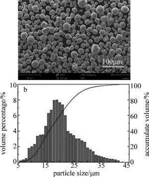
实验中选用材料为316L不锈钢粉末。该粉末由英国Renishaw公司提供,为气雾化技术制备球形粉末,其粒径范围为5μm~41μm,其粉末形貌与粒径分布如图 1所示。其元素含量组成如表 1所示。
Table 1. Content of 316L stainless steel elements
element Cr Ni Mo Mn Si N O P C S Fe mass fraction 0.16~0.18 0.10~0.14 0.02~0.03 0.02 0.01 0.001 0.001 0.00045 0.0003 0.0003 balance -
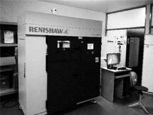
本文中采用的实验设备为英国Renishaw公司AM400机型,如图 2所示。该机采用功率最大为400W的光纤激光器,激光光斑直径为70μm,调制脉冲输出模式,振镜式激光扫描。系统工作舱最大成形尺寸为250mm×250mm×300mm,腔室采用保护气体为氩气。
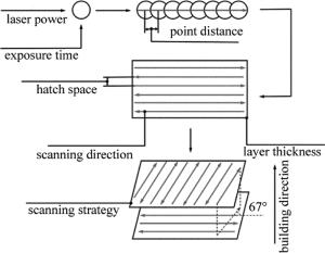
设备成形过程如图 3所示。通过设置不同的激光功率与曝光时间可以成形相应工艺参量条件下的单熔点,添加点距的设置可以成形单熔道,再添加线间距与扫描策略即可成形单层,通过点线面的成形方式最终构成块体。其可变参量分别为激光功率、曝光时间、点距、线间距、铺粉层厚、扫描策略[5-7]。
-
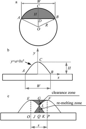
搭接理论模型如图 4所示,其中H为熔点或熔道熔高,W为熔宽,s为间距。由于假设重熔区内的熔液会进入间隙区,因此,如图 4c所示,当间距s设置合理时,面积SEFL=SJKL,此时熔道表面光滑平整,有SEFPO=2SEOK=2SPFJ=Hs,即当熔道截面积SABC=Hs时,其成形表面最好[8-13]。
在弓形模型中,如图 4a所示, 已知熔点的高和宽,则可知弓形模型的弦长AB和弦高CD,利用函数的泰勒级数可近似得出弓形面积Sb:
$ {S_{\rm{b}}} = \frac{2}{3}HW + \frac{8}{{15}}\frac{{{H^3}}}{W} - \frac{{32}}{{105}}\frac{{{H^5}}}{{{W^3}}} + \frac{{128}}{{315}}\frac{{{H^7}}}{{{W^5}}} - \cdots $
(1) 已知Hs=Sb时成形表面最好,则有间距$ {S_{\rm{b}}} = \frac{2}{3} \times HW + \frac{8}{{15}}\frac{{{H^3}}}{W} - \frac{{32}}{{105}}\frac{{{H^5}}}{{{W^3}}} + \frac{{128{H^7}}}{{315{W^5}}} - \cdots $。
在抛物线模型中,如图 4b所示, 可知A(-W/2, 0), B(W/2, 0), C(0, H) 3个点的坐标,将A, B, C 3个点的坐标带入抛物线公式y=a+bx2,有$ a = H, b = - \frac{{4H}}{{{W^2}}} $,可得熔点轮廓线的数学表达式:
$ y = H\left[ {1 - {{\left( {\frac{{2x}}{W}} \right)}^2}} \right] $
(2) 当SEFL=SJKL,即SEGL=SKQL时,有:
$ \int_0^{s/2} {(H - y){\rm{d}}x = \int_{s/2}^{W/2} {y{\rm{d}}x} } $
(3) $ \int_0^{s/2} {H{\rm{d}}x = \int_0^{W/2} {y{\rm{d}}x} } $
(4) 将(2)式带入(4)式可得Hs/2=HW/3,得出s=2W/3。综上所述,间距s的设置只与熔宽W有关,当间距设置为2W/3时,得出的熔道表面质量最佳。
-
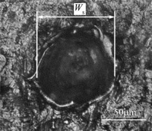
在单熔点实验中,设置激光功率为200W,铺粉层厚为50μm,曝光时间分别设为40μs, 60μs, 80μs, 100μs, 120μs,对不同曝光时间下成形的单熔点采用超景深显微镜(KEYENCE,VHX-600E,Japan)进行拍照,采用ImageJ软件对熔宽多次测量取平均值,其测量示意图如图 5所示。
-
单熔道实验中,固定激光功率为200W,铺粉层厚为50μm,分别对40μs, 60μs, 80μs, 100μs, 120μs这5个曝光时间设置5个不同的点距,Ws表示单熔点的熔宽,Ws的数值由单熔点实验中测量得出,实验设计数据如表 2所示,实验结果采用超景深显微镜进行表面形貌观测。
Table 2. Design of single cladding experiment under different exposure time and point distances
exposure time/μs point distance/μm Ws/5 Ws/3 Ws/2 2Ws/3 4Ws/5 40 16 26 39 52 62 60 16 27 41 55 66 80 18 30 45 60 72 100 20 33 49 65 78 120 21 35 52 69 83 -
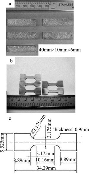
多层块体实验中选取了单熔道成形效果较好的一组数据,激光功率为200W,铺粉层厚为50μm,曝光时间为100μs,点距为65μm,此时单熔道宽度W=154μm,扫描线间距s分别设为31μm(W/5), 51μm(W/3), 77μm(W/2),103μm(2W/3), 138μm(4W/5)。成形样件尺寸为40mm×10mm×6mm。
多层块体的实验结果采用了扫描电镜(PHENOM XL, Netherlands)对样件表面形貌拍照,并观测表面形貌单熔道的搭接情况;对样件进行线切割制备出截面,经过磨抛和腐蚀,腐蚀液配比为4mL HF, 4mL HNO3和92mL C2H5OH,通过采用光学显微镜(DM4000M, Leica, Wetzlar, Germany)观察截面形貌,通过截面法计算样件的致密度并对样件缺陷进行了分析;将样件在金相显微镜(Leica, DM4000M, Germany)下进行光学照片拍摄,并分析了截面微观组织;最终将样件按照图 6c中尺寸进行线切割, 得出拉伸试样如图 6b所示,并对样件进行拉伸力学性能测试,拉伸设备为Instron 5966(Instron, Boston, USA),得出5个样件的屈服强度、抗拉强度、延伸率。
-
单熔点熔宽检测结果如表 3所示。可以看出,随着曝光时间增大,单熔点熔宽增大,这是由于随着曝光时间增大,激光能量密度增大,已熔化的熔池不断进行吸粉,从而使熔化的粉末量和重熔量较多,单熔点熔宽增大[13-14]。
Table 3. Width measurement of single melting point under different exposure time
exposure time/μs width of melting point Ws/μm 40 78 60 82 80 90 100 98 120 104 -
单熔道的成形质量对于多层块体的成形有直接影响,根据以往的研究,单熔道表面形貌连续稳定时,较易获得高致密度成形块体,因此通过单熔道实验可以为多层块体成形初步筛选出较好的工艺参量[5]。
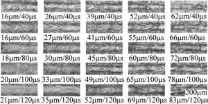
图 7为不同点距和曝光时间下的单熔道表面形貌。由图中可以观察到:(1)当曝光时间为40μs、点距为16μm~26μm时,单熔道形貌较为稳定,但当点距大于39μm时,单熔道表面凝固线开始变得不均匀,这可能是由于随着点距增大,单位长度上熔化的粉末减少,熔池中熔液较少,使得熔池中熔液整体冷却速度过快,因而无法形成连续均匀的凝固线,当点距达到52μm时,可以看出单熔道宽度明显变细;(2)当曝光时间为60μs、点距为16μm~27μm时,单熔道形貌较为稳定,当点距大于41μm时,单熔道粗细不均匀,这是可能是由于当激光能量输入一定时,熔液量一定,点距由小变大会使熔液量逐渐不足,特别是在熔点之间的搭接处熔液量容易出现不足,从而导致单熔道在搭接处收缩;(3)当曝光时间为80μs、点距为18μm~45μm时,单熔道较为稳定,随点距进一步增大,熔道明显变细;(4)当曝光时间为100μs、点距为20μm~65μm时,单熔道较为稳定,可以看出,随着曝光时间的增大,凝固线由锐角逐渐变为钝角,这是由于随着曝光时间的增大,熔池内熔液数量变多,其整体的冷却速度变慢,从而使凝固线呈现钝角;(5)当曝光时间为120μs、点距为21μm~69μm时,单熔道较为稳定,可以看出,随着曝光时间增大,单熔道形貌较好的对应的点距随之增大,这是因为曝光时间延长,会使熔池增大,熔池充分铺展,从而能够适当增大点距。
由以上分析可以看出,当曝光时间为40μs和60μs时,成形效率较高表面形貌较好的点距约为Ws/3,此时点距较为合理,搭接率约为30%;当曝光时间为80μs时,合理的点距约为Ws/2,搭接率约50%;当曝光时间为100μs和120μs时,合理的点距可取为2Ws/3,搭接率约为60%。可以看出,当曝光时间为40μs,60μs,80μs时,实验结果并没有完全符合搭接理论模型,这可能是由于在取不同的点距和曝光时间时,单熔道的截面形貌并不能完全符合弓形和抛物线模型,当取点距与曝光时间之比较大时,由于激光穿透深度较小,重熔区域较小,且由于熔池冷却速度较快、润湿性较差等因素,熔池内的熔液大部分为粉末熔化所得,少部分为重熔凝固层所得,造成大部分熔液位于凝固层表面,因此可能会造成熔池凸起面积较大,从而与搭接理论模型有所偏差[15-19]。
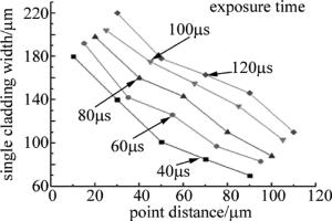
图 8为不同曝光时间和点距下的单熔道宽度,即对图 7采用ImageJ软件进行熔宽测量。由图中可以看出,单熔道宽度随着曝光时间的增大而增大,这是由于曝光时间的增加使得激光输入的能量密度增加,在单个熔点上熔化的粉末增加,从而使得单熔道变宽;此外,单熔道的宽度随着点距的增大而减小,这是由于在曝光时间一定时,点距增大使得熔池中的熔液一定的情况下,相邻两个熔池之间的搭接区域变小,从而导致单熔道宽度变小。激光能量密度E的定义为[5]:
$ E = \frac{{Pt}}{{hsd}} $
(5) 式中,E为激光能量密度,P为激光功率,t为曝光时间,s为扫描线间距,h为层厚,d为点距。
-
如图 9a和图 9b所示,当扫描间距s < W/3时,单熔道之间搭接较为密集,成形面整体凹凸不平,这是由于搭接重合区域过大,重熔区域的熔液溢出较多所导致,且由于单位面积内单熔道数量较多,形成的飞溅数量也多[8-9, 20]。
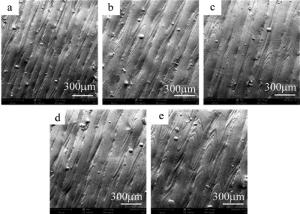
Figure 9. Scanning electron microscope figure of multilayer blocksurface under different scanning intervals
如图 9c和图 9d所示,当s为W/2~2W/3时,其飞溅的数量大大减少,成形平面也较为平整,此时扫描间距设置较为合理。
如图 9e所示,当s=4W/5时,成形平面又趋于凹凸不平,这是由于搭接区域较小,使得单熔道之间产生凹陷,且随着成形层数的增加,其表面的粗糙度也越大。
-
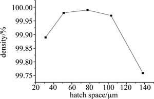
如图 10所示,通过ImageJ软件进行截面孔洞面积统计,可以计算的出样件的致密度曲线,由图可以看出样件致密度随着线间距的增大,呈现先增后减的趋势,线间距为W/3~2W/3时,致密度总体较高,其中致密度最高可达99.99%。
图 11为不同线间距下多层块体截面形貌。由图 11a和图 11b可以看出,截面中含有部分飞溅夹渣,这主要是因为线间距设置较小,使得单位面积内的单熔道过多,从而产生较多飞溅,较小的飞溅颗粒在下一层成形时,会被重熔而不会对样件的致密度造成影响,但较大的飞溅颗粒在下一层成形时可能无法被完全熔化,因而造成夹渣甚至会产生孔隙;由图 11c可以看出,其截面无明显缺陷,致密度较好;由图 11d和图 11e可以看出,截面中含有未熔合缺陷,图 11d中较少,而图 11e中较为严重,这可能是由于随着线间距的增大,单熔道之间的间隔逐渐增大,从而在部分单熔道之间熔液无法充分填充空隙,或在上下单层之间,激光未能充分重熔部分搭接区域,从而导致孔隙[21-23]。
-
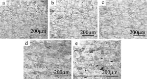
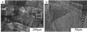
选择多层块体中致密度较高的(功率200W, 层厚50μm,曝光时间100μs,点距65μm,线间距77μm)部分进行微观组织观测,其截面微观组织如图 12所示。
316L不锈钢为低碳钢,其中C的质量分数不大于0.0003,由图中可以看出,其微观组织主要由残余奥氏体和铁素体构成,由晶体形态为等轴晶和柱状晶,由于采用的铺粉层厚较薄,激光能量输入适中,在激光扫描过后,熔池快速冷却,促使了熔池中未凝固熔液中游离晶体的择优长大,从而生成大量等轴晶,但也存在部分的柱状晶形成[5]。
-
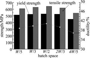
由图 13可知,当线间距为W/2时,其屈服强度为530MPa,拉伸强度为645MPa,延伸率为41%,高于316L不锈钢的锻件标准(ASTM A473-13),即屈服强度为170MPa,拉伸强度为450MPa,延伸率为40%[24-25]。当线间距分别为W/5, W/3, W/2时,块体强度与延伸率整体呈现上升趋势,这可能是由于随着线间距增大,样件单位面积内单熔道数量减少,其飞溅数量减少,样件中的飞溅造成的夹渣和气孔数量减少,使得其内部缺陷减小,从而使力学性能逐渐变好;而当线间距由W/2增大到4W/5时,由于线间距的增大,样件内部逐渐产生未熔合缺陷,这对样件的致密度和拉伸力学性能都造成了较大的影响[26-29]。
-
脉冲式激光选区熔化成形相比连续式,其点距与曝光时间之比近似等于连续式激光器中扫描速度,由于参量上的细化,使得其单熔点与单熔道的成形过程也可控,为多层块体成形提供了基础与保障,精度与灵活性也更高。
(1) 单熔点实验表明,当激光功率一定时,随着曝光时间增大,单熔点的熔宽也增大;当曝光时间为40μs时,单熔点熔宽为78μm; 当曝光时间增大至120μs时,单熔点熔宽为104μm。
(2) 单熔道实验表明,在功率为200W、层厚为50μm、其曝光时间为40μs~60μs时,合理的点距为Ws/3,搭接率约为30%;当曝光时间为80μs时,合理的点距为Ws/2,搭接率约为50%;当曝光时间为100μs~120μs时,合理的点距为2Ws/3,搭接率约为60%;搭接率随着曝光时间的增大而逐渐趋近于搭接理论模型。
(3) 在多层块体实验中,综合表面形貌、致密度、缺陷、微观组织与拉伸性能,单熔道的扫描线间距为W/2,即搭接率约为50%时,成形件的表面形貌最为平整,飞溅数量最少。
(4) 当功率为200W、层厚为50μm、曝光时间为100μs、点距为65μm、线间距为77μm时,得到的样件致密度达到最高为99.99%;微观组织中主要为残余奥氏体与铁素体,其中大部分为等轴晶和少量等轴晶;拉伸力学性能为屈服强度530MPa,拉伸强度645MPa,延伸率41%,高于316L不锈钢的锻件标准(ASTM A473-13)。
脉冲式激光选区熔化成形搭接率的研究
Study on overlap ratio of pulse laser selective melting forming
-
摘要: 为了探究脉冲式激光选区熔化成形过程中的搭接率与搭接特性,采用了弓形与抛物线形搭接理论模型,并设计了单熔点、单熔道和多层块体的成形实验,获得了不同条件下较优的搭接率。结果表明,单熔点熔宽随曝光时间增大而增大;单熔道实验中,曝光时间为40μs~60μs时,单熔点间较合理的搭接率约为30%;曝光时间为80μs时,搭接率约为50%;曝光时间为100μs~120μs时,搭接率约为60%;多层块体实验中,单熔道间的搭接率为50%时,块体表面形貌较好;通过对块体进行致密度、缺陷、微观组织和拉伸性能分析可知,当功率200W、层厚50μm、曝光时间100μs、点距65μm、线间距77μm时,可得到致密度最高为99.99%的样件。该研究对认识脉冲式激光选区熔化成形过程中的搭接特性和搭接率选取是有帮助的。Abstract: In order to study overlap ratio and overlap characteristics during pulse laser selective melting forming process, the overlap theoretical models of bow and parabola were adopted, and the forming experiments of single melting point, single cladding and multi-layer block were designed under different conditions to obtain the optimal overlap ratio. The results show that the width of single melting point increases with the increase of exposure time. The optimal overlap ratio between two melting tracks is 30% in the single cladding experiment when exposure time is 40μs~60μs. The overlap ratio is 50% when exposure time is 80μs. The overlap ratio is 60%, when exposure time is 100μs~120μs. The surface morphology of block is slat in the multi-layer block experiment when overlap ratio between two melting tracks is 50%. After the analysis of block density, defect, microstructure and tensile properties, sample density is up to 99.99%, when laser power is 200W, layer thickness is 50μm, exposure time is 100μs, point distance is 65μm and line spacing is 77μm. The research is helpful for understanding overlap characteristics and overlap ratio selection in pulse laser selective melting.
-
Key words:
- laser technique /
- overlap ratio /
- overlap theory model /
- density /
- microstructure /
- tensile property
-
Table 1. Content of 316L stainless steel elements
element Cr Ni Mo Mn Si N O P C S Fe mass fraction 0.16~0.18 0.10~0.14 0.02~0.03 0.02 0.01 0.001 0.001 0.00045 0.0003 0.0003 balance Table 2. Design of single cladding experiment under different exposure time and point distances
exposure time/μs point distance/μm Ws/5 Ws/3 Ws/2 2Ws/3 4Ws/5 40 16 26 39 52 62 60 16 27 41 55 66 80 18 30 45 60 72 100 20 33 49 65 78 120 21 35 52 69 83 Table 3. Width measurement of single melting point under different exposure time
exposure time/μs width of melting point Ws/μm 40 78 60 82 80 90 100 98 120 104 -
[1] STOPYRA W, KYRZAC J, GRUBER K, et al.Influence of laser power on the penetration depth and geometry of scanning tracks in se-lective laser melting[J]. Proceedings of the SPIE, 2016, 10159:101590R. doi: 10.1117/12.2262079 [2] ZHANG D Y, FENG Q H, LI Zh B, et al. Application of laser direct manufacturing of metallic part in aerospace industry[J].Aeronautical Manufacturing Technology, 2011(9):38-41(in Chinese). [3] DEMIR A G, COLOMBO P, PREVITALI B. From pulsed to continuous wave emission in SLM with contemporary fiber laser sources:effect of temporal and spatial pulse overlap in part quality[J].International Journal of Advanced Manufacturing Technology, 2017, 91(5/8):2701-2714. [4] LIU R Ch, YANG Y Q, WANG D. Research of upper surface roughness of metal parts fabricatedby selective laser melting[J]. Laser Technology, 2013, 37(4):425-430(in Chinese). [5] CHERRY J A, DAVIES H M, MEHMOOD S, et al.Investigation into the effect of process parameterson microstructural and physical properties of 316L stainless steel parts by selective laser melting[J].International Journal of Advanced Manufacturing Technology, 2015, 76(5/8):869-879. [6] WANG D, YANG Y Q, SU X B, et al. Study on energy input and its influences on single-track, multi-track, and multi-layer in SLM[J]. International Journal of Advanced Manufacturing Technology, 2012, 58(9/12):1189-1199. [7] WANG D, WU Sh B, MAI Sh Zh, et al.Mechanisms and characteristics of spatter generation in SLM processing and its effect on the properties[J].Materials & Design, 2017, 117:121-130. [8] GU D D, SHEN Y F. Balling phenomena in direct laser sintering of stainless steel powder:Metallurgical mechanisms and control methods[J]. Materials & Design, 2009, 30(8):2903-2910. [9] ZHANG G, WANG J H, ZHANG H. Research progress of balling phenomena in selective laser melting[J].Foundry Technology, 2017, 38(2):262-265(in Chinese). [10] WANG J H, BAI P K.Study on process parameters on surface quality of Ti6Al4V by selective laser melting[J]. Hot Working Technology, 2013, 42(15):13-15(in Chinese). [11] ZHOU X, LIU W. Melting and solidifying behavior in single layer selective laser of pure tungsten powder[J]. Chinese Journal of Lasers, 2016, 43(5):0503006(in Chinese). doi: 10.3788/CJL [12] SUN Zh J, TAN X P, TOR Sh B, et al.Selective laser melting of stainless steel 316L with low porosity and high build rates[J].Materials & Design, 2016, 104:197-204. [13] ZHANG Y Zh, LIU F R, CHEN J M, et al. Effects of surface quality on corrosion resistance of 316L stainless steel parts manufactured via SLM[J]. Journal of Laser Applications, 2017, 29(2):022306. doi: 10.2351/1.4983263 [14] LI R D, LIU J H, SHI Y S, et al. 316L stainless steel with gradient porosity fabricated by selective laser melting[J]. Journal of Materials Engineering & Performance, 2010, 19(5):666-671. [15] YASA E, KRUTH J P. Microstructural investigation of selective laser melting 316l stainless steel parts exposed to laser re-melting[J]. Procedia Engineering, 2011, 19(1):389-395. [16] BRANDL E, HECKENBERGER U, HOLZINGER V, et al.Additive manufactured AlSi10Mg samples using selective laser melting (SLM):Microstructure, high cycle fatigue, and fracture behavior[J]. Materials & Design, 2012, 34:159-169. [17] SUN T T, YANG Y Q, SU X B, et al.Research on densification of 316L stainless steel powder in selective laser melting process[J]. Laser Technology, 2010, 34(4):443-446(in Chinese). [18] LU J B, YANG Y Q, WANG D, et al. Analysis of affecting factors of overhanging surface quality by selective laser melting[J]. Laser Technology, 2011, 35(2):148-151(in Chinese). [19] WANG M Y, ZHU H H, QI T, et al. Selective laser melting Al-Si aluminum alloy and the crack formation mechanism[J]. Laser Technology, 2016, 40(2):219-222(in Chinese). [20] ZHANG X Y, FANG G, ZHOU J. Additively manufactured scaffolds for bone tissue engineering and the prediction of their mechanical behavior:A review[J]. Materials, 2017, 10(1):50-54. doi: 10.3390/ma10010050 [21] FRAZIER W E. Metal additive manufacturing:A review[J]. Journal of Materials Engineering and Performance, 2014, 23(6):1917-1928. doi: 10.1007/s11665-014-0958-z [22] YAN C, HAO L, HUSSEIN A, et al.Advanced lightweight 316L stainless steel cellular lattice structures fabricated via selective laser melting. Materials & Design, 2014, 55:533-541. [23] MA M, WANG Z, ZENG X. A comparison on metallurgical behaviors of 316L stainless steel by selective laser melting and laser cladding deposition[J]. Materials Science and Engineering, 2017, A685:265-273. [24] AHMADI A, MIRZAEIFAR R, MOGHADDAM N S, et al. Effect of manufacturing parameters on mechanical properties of 316L stainless steel parts fabricated by selective laser melting:A computational framework[J]. Materials & Design, 2016, 112:328-338. [25] LI P, WANG Z, PETRINIC N, et al.Deformation behaviour of stainless steel micro lattice structures by selective laser melting[J]. Materials Science and Engineering, 2014, A614(5):116-121. [26] GUNENTHIRAM V, PEYRE P, SCHNEIDER M, et al.Analysis of laser-melt pool-powder bed interaction during the selective laser melting of a stainless steel[J]. Journal of Laser Applications, 2017, 29(2):022303. doi: 10.2351/1.4983259 [27] ZHANG B, DEMBINSKI L, CODDET C. The study of the laser parameters and environment variables effect on mechanical properties of high compact parts elaborated by selective laser melting 316l powder[J]. Materials Science and Engineering, 2013, A584(6):21-31. [28] MIRZA F, CHEN D. A unified model for the prediction of yield strength in particulate-reinforced metal matrix nanocomposites[J]. Materials, 2015, 8(8):5138-5153. doi: 10.3390/ma8085138 [29] WANG D, YANG Y, HUANG Y L, et al.Impact of inter-layer scan strategy on quality of direct fabrication metal parts in SLM process[J]. Laser Technology, 2010, 34(4):447-451(in Chinese). -


 网站地图
网站地图

 下载:
下载:
