Analysis of the influence of pulse width and repetition frequency on damage threshold of HgCdTe detector
-
摘要: 为了研究脉宽及重频对HgCdTe探测器损伤阈值影响,采用有限元法对HgCdTe红外探测器进行2维建模,以及激光辐照探测器温度场的仿真,得到了波段内外脉宽从10ns~1000ns的单脉冲激光损伤阈值。由于采用实验测定所有脉宽激光损伤阈值的办法不现实,故通过仿真计算,给出了从ns~μs量级不同激光脉宽的单脉冲探测器损伤阈值公式。结果表明,波段外单脉冲损伤阈值为9MW/cm2~0.9MW/cm2,波段内为150MW/cm2~15MW/cm2,并且探测器单脉冲损伤阈值与激光脉冲宽度呈负指数关系;当采用重频激光辐照探测器时,在相同的重复频率下,因长脉冲激光比窄脉冲宽激的脉冲间隔小,故长脉冲激光辐照时更容易出现温度积累效应,从而出现大面积损伤。这为进一步研究探测器的热应力场热弹性波和激光防护等提供了重要的理论分析依据。Abstract: In order to study the influence of pulse width and repetition frequency on the damage threshold of HgCdTe detector, finite element method was used to build 2-D model of HgCdTe infrared detector and the temperature field of laser irradiation detector was simulated. Damage threshold of single pulse laser of off-band and in-band was obtained from the range of 10ns to 1000ns. Measurement of damage threshold of all pulse width was hard. After simulation and calculation, the damage threshold formula from the range of 10ns to 1000ns was concluded. The results show that, single pulse laser damage threshold of off-band laser is 9MW/cm2~0.9MW/cm2, and 150MW/cm2~15MW/cm2 for in-band laser. And single pulse damage threshold has the negative exponential relationship with laser pulse width. And then, repetition frequency laser was used to irradiate detector with the same repetition frequency. The temperature accumulation effect and damages of large area are more likely to occur under long pulse laser irradiation, because pulse separation of long pulse laser is smaller than narrow pulse laser. The research is useful for studying stress field distribution、thermoplastic wave and laser protection.
-
Keywords:
- laser technique /
- damage threshold /
- finite element /
- HgCdTe /
- pulse laser
-
引言
随着红外探测技术的发展,碲镉汞(mercury cadmium telluride,HgCdTe)光电探测器由于其高灵敏度、宽响应波段和响应时间短等许多优点已被广泛于军事、气象和光通信等领域。但由于光电探测系统属于弱光学探测系统,在其响应波段内具有很大的增益,导致HgCdTe探测器极易受到激光辐照的干扰,严重时会使HgCdTe的组成材料及结构发生不可逆转的硬破坏[1]。因此研究激光辐照对HgCdTe探测器性能的影响具有重要意义。目前,国内外已经开展了不少有关激光辐照HgCdTe探测器的理论和实验研究。BARTOLI[2]等人采用10.6μm激光通过实验测量了Hg0.8Cd0.2Te的损伤阈值。JEVITĆ[3]等人仿真计算了采用脉宽为50ns的红宝石激光器与脉宽为8ns的Nd:YAG激光器辐照时HgCdTe的损伤阈值与熔化深度。GARG[4-5]等人通过实验研究了脉宽为20ns激光辐照时,Hg0.8Cd0.2Te的单脉冲、5个脉冲与10个脉冲的损伤情况,证明了累计损伤效应。国内JIANG等人[6]通过测量1064μm、Nd:YAG激光辐照HgCdTe探测器前后探测器电阻的瞬变行为,指出激光热损伤存在3种行为,并计算在3种热损伤机制下的激光损伤功率密度阈值。LI等人[7]用波段内和波段外连续激光辐照PC型HgCdTe红外探测器,给出了1.319μm波段内激光辐照下探测器的饱和阈值,分析了采用波段外连续激光辐照探测器时,探测器的响应主要以热效应为主。ZHANG[8]和WANG[9]等人通过理论和实验分别得到了干扰和损伤星载HgCdTe探测器所需的脉冲CO2激光的脉冲能量密度阈值和连续CO2激光10km远场干扰损伤HgCdTe探测器能量密度阈值。WANG[10]等人通过实验观察到重频对HgCdTe温升的影响较小,但其只以重频为变量,并未考虑脉宽与重频对温升的共同作用。LI等人[11]利用有限元分析法,建立了HgCdTe红外探测器3维仿真模型,计算了脉宽为10ns不同功率密度激光辐照下碲镉汞层和铟柱最高温度。上述工作大多集中在分析探测器的干扰和损伤阈值,但关于激光脉宽和重频与损伤阈值、损伤程度之间的关系研究,在作者所查文献范围内鲜有报道。
本文中采用有限元仿真软件对HgCdTe红外探测器采用参量化建模的方法,建立了HgCdTe红外探测器的2维模型,对探测器正面受到脉宽为ns~μs量级的高斯脉冲激光照射后的温度场进行了模拟,并对其结果进行分析。
1. 理论基础
1.1 HgCdTe探测器基础模型
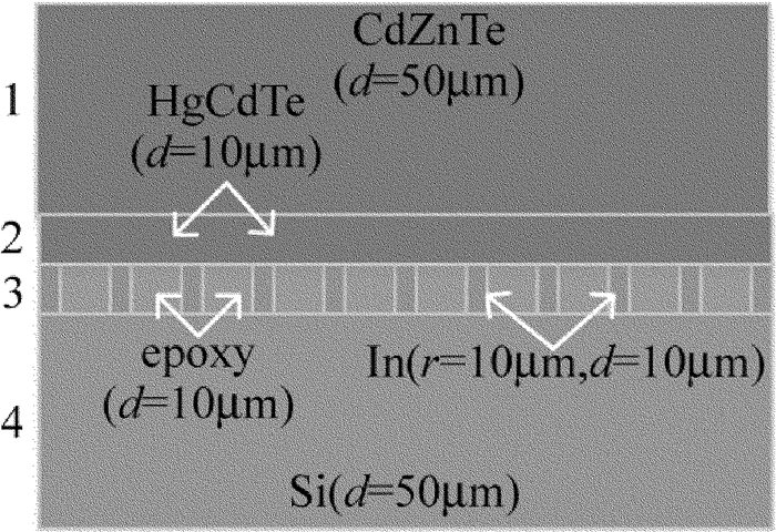
HgCdTe由于其优越的性能,一直在红外领域占据着重要的地位,其发展大致可分为三代[12]:一代为1维光导线列; 二代为2维光伏阵列器件; 三代则为大面阵凝视器件。HgCdTe探测器的结构比较复杂,为便于分析,现只考虑直接倒焊单铟柱结构探测器,并将探测器简化为4层,如图 1所示。第1层是碲锌镉(cadmium zinc telluride, CdZnTe),厚度d=50μm; 第2层是碲镉汞(HgCdTe),厚度d=10μm;第3层中较窄部分是铟(indium bump,In)柱,铟柱高d=10μm,半径r=10μm,较宽部分是环氧树脂(epoxy); 第4层是硅(silicon, Si)基底,厚度d=50μm。HgCdTe探测器受到波段内激光辐照时,因CdZnTe层的吸收系数较低,且透过率高,故在此不考虑激光对衬底的加热,而是将激光直接加载在HgCdTe层上。其2维简化模型如图 1所示[13], 探测器各层材料的热学参量如表 1所示。
Table 1. Thermal parameters of detector materialmaterial density ρ /
(kg·m-3)heat capacity cp /
(J·kg-1·K-1)thermalconductivity κ /
(W·m-1·K-1)CdZnTe 5680 159 0.97 HgCdTe 7600 150 20 In 7310 237.6 82.01 epoxy 1250 1530 0.2 Si 2330 550 250 1.2 热传导理论
经典的热传导微分方程可表示为[14]:
∇[κ(T)∇T]+q(x,y,z,t)=ρ(T)cp(T)∂T∂t (1) 式中,κ(T)为材料的热导率,T为温度,q(x, y, z, t)为单位时间内材料内部的生热率,ρ(T)为材料密度,cp(T)为材料的比定压热容,t为时间。因为HgCdTe材料的吸收系数α较大,约为1×10⁵m-1,而In对激光的反射率较高,环氧树脂对激光的吸收率仅为510m-1,故只考虑HgCdTe层对激光能量的吸收。当脉冲激光辐照材料时,若激光光斑尺寸远大于激光脉冲作用时间内的热传播深度,则激光辐照下材料的温升可近似地当成1维热传导问题来处理,此时热传导微分方程可转换为:
∂∂z(κ∂T∂z)+q−ρcp∂T∂t=0 (2) 探测器工作温度为77K,Si底层温度为恒定77K,因激光加热时间较短,可不考虑探测器与空气之间的对流,故在激光辐照过程中可将初始条件和边界条件写为[15]:
{−κ∂T∂z|z=0=(1−R)I(z,t),(inband)−κ∂T∂z|z=0=(1−R)βI(z,t),(inband) (3) T|t=0=77 (4) T(t)|z=l=77 (5) 式中,R为反射率,β为综合吸热系数,I(z, t)为脉冲激光的功率密度, l为探测器总厚度。
当激光脉冲结束后,探测器内的温度场属于无热源冷却情况,热传导方程可简化为:
∂∂z(κ∂T∂z)−ρcp∂T∂t=0 (6) 其初始条件即为激光加热后的温度场分布,边界条件依然可以利用(5)式来描述。
2. 仿真结果分析
2.1 波段外不同脉宽,单脉冲损伤阈值
HgCdTe晶体的自由电子碰撞时间约为10-14s[16],电子晶格碰撞的弛豫时间约为10-14s,当激光脉宽小于晶体的自由电子碰撞时间或电子晶格碰撞时间时,激光与材料的相互作用将会出现一些非线性现象,所以本文中在进行仿真计算时仅考虑脉冲宽度为ns~μs的激光。在此以探测器发生点损伤,即使光敏材料达到熔点温度时的激光功率密度作为损伤阈值,表 2是仿真计算得到的从10ns~1000ns的波段外激光单脉冲损伤阈值。
Table 2. Damage threshold of power density of off-band laserpulse width
/nspower density/
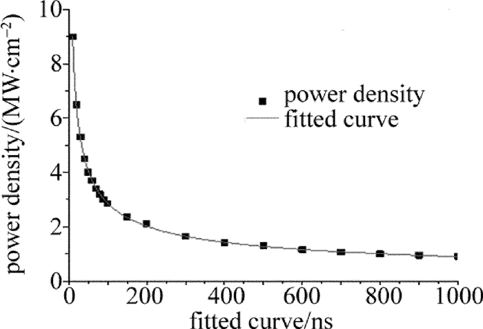
(MW·cm-2)10 9 20 6.5 30 5.3 40 4.5 50 4 60 3.7 70 3.4 80 3.2 90 3 100 2.85 150 2.35 200 2.1 300 1.65 400 1.41 500 1.3 600 1.15 700 1.06 800 1 900 0.94 1000 0.9 研究表明,当温度大于353K时,Hg原子会从HgCdTe晶体中析出,破坏HgCdTe晶体结构,从而影响探测器性能; 当温度大于423K时,In柱可能从HgCdTe上脱落; 当温度达到HgCdTe的熔点993K时,虽仍有光电效应,但不能收集光生载流子以达到对入射光响应,故探测器将被彻底破坏。采用表 2的数据利用最小二乘法进行拟合得到脉宽为ns~μs量级,波段外探测器损伤阈值曲线与公式。拟合曲线如图 2所示。
图 2中因为在100ns以内阈值功率密度变化较大,所以设置的数据点较多,100ns~1000ns段变化较平缓,数据点选取得相对少一些,得到的拟合公式为:
P=29.833×(τ+0.525)−0.508 (7) 式中,P为功率密度,τ为激光脉宽,单位为ns。(7)式与数据点拟合良好,可以采用(7)式来描述激光脉宽与单脉冲损伤阈值的关系。另外从表 2中可以看到,10ns~1000ns的单脉冲损伤阈值随着脉宽的增加而减小,脉宽增大100倍,阈值功率减小10倍,图 2和(7)式显示,这种减小趋势并非是线性减小,而是以脉宽为底的指数减小的关系。因为达到损伤阈值所需的能量是一定的,激光脉宽增大,意味着作用时间变长,若功率密度相同,在一个脉冲时间内长脉冲激光将输出比短脉冲激光更多的能量,因此长脉冲激光的阈值功率密度比短脉冲激光的要低,但阈值功率与脉宽并不是线性关系,因为在激光作用期间,探测器不仅在吸收激光的能量,同时在将热量往四周扩散,时间越长,扩散的热量越多,因而阈值功率与脉宽并非线性关系。
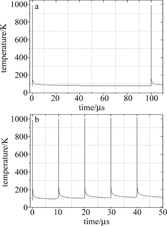
本文中以工作在阈值功率,脉宽为10ns波长为1.064μm的Nd:YAG辐照工作波段为8μm~14μm的HgCdTe探测器为例[16],计算了重复频率为1Hz、10kHz和100kHz时激光辐照探测器的温度场情况,结果如图 3所示。因为考虑现实中重复频率高于100kHz的激光器并不常见并已接近准连续激光,所以在此只考虑从10kHz~100kHz的激光重复频率。从计算结果中可以发现,重复频率为100kHz时,HgCdTe层内温度场与10kHz时的稍微有点区别,两种情形皆在脉冲时间内迅速升温,脉冲结束后又迅速冷却[17],但在重复频率为100kHz时可以在HgCdTe层看到一点点的温度积累效应,在10kHz频率下则无,这可以解释为脉冲间隔时间大于探测器冷却到初始温度的时间,所以后续激光脉冲不能加载在前一个脉冲的剩余热量之上[18]。从仿真的数据点可以得到HgCdTe冷却到初始温度的时间为125μs,在10μs(100kHz)时冷却到90K,100μs(10kHz)时冷却到了78K,所以重频为100kHz时可以看得到温度积累效应,而重频为10kHz时基本看不到温度积累。故得出结论:当脉冲间隔时间大于探测器冷却到初始温度的时间时,探测器光敏层的损伤只与单脉冲功率密度有关,而与重复频率无关。若重复频率足够大到脉冲间隔时间小于探测器冷却到初始温度的时间,则光敏层可能会因为温度积累效应而造成损伤。但考虑到激光器制作难度,研究重频超过100kHz的情况并无多大的意义。使用脉宽更大的激光辐照探测器时,在相同的重复频率下,由于脉冲间隔时间更小,其大于冷却时间的可能性就更大,热量就更容易累积。所以在高重频激光辐照下,长脉宽激光比窄脉宽激光更容易对探测器造成损伤。所以在脉冲激光损伤探测器的过程中,不能单一的只考虑激光功率密度、脉冲宽度或重复频率对探测器瞬时温度场的贡献,在激光作用期间,探测器的瞬时温度场其实是激光功率密度、脉冲宽度和重复频率共同作用的结果。
HgCdTe探测器若温度过高或长时间受到激光辐照达到热平衡,且热平衡温度大于损伤阈值,就有可能导致多数HgCdTe单元Hg析出、铟柱脱落或HgCdTe熔化导致像元四周的金属线短路或断路,致使信号的选通和输出发生故障,从而造成大面积损伤。所以即使不是工作在阈值功率,若存温度累积效应,在长时间照射下,只要热平衡温度能够超过损伤阈值,探测器就会因为累积效应造成大面积永久损伤。
2.2 波段内不同脉宽,单脉冲损伤阈值
波段外激光辐照探测器时,探测器对辐照激光的响应以热效应为主,而当波段内功率较小的激光辐照探测器时,探测器的响应以光效应为主,辐照功率逐渐加大后,热效应才开始明显表现出来,当波段内激光辐照到探测器上时,光敏材料吸收光子能量激发出光生载流子,使得P-N结内电子密度增大,电子产生的声子与晶格声子碰撞弛豫以后产生成热,故一旦导带电子密度超过临界值,就会对探测器造成破坏。其中光敏材料吸收的激光能量有一部分用来使处于低价带的电子激发成为自由电子,另一部分的光能转换为热能,从静止的角度看,当半导体材料吸收一个光子后,成为一个可导热的热电子,通过弛豫变为处于导带底附近的可导电冷电子,因此吸收的一个激光光子能量中仅有部分转变为热能,用公式可表达为[19]:
E=hν−Eghν (8) β≈hν−Eghνα (9) 式中, E为光能转变成的热能,h为普朗克常数,ν为激光频率,Eg为禁带宽度, β为综合吸热系数,α为光学吸收系数。从式中可以看出,波段内激光与探测器相互作用原理与波段外激光的大不相同,在波段内激光辐照探测器时,若想使探测器温度达到损伤阈值,则需要克服电子跃迁损失掉的能量,因此,波段内激光损伤探测器所需的激光功率密度阈值将会更高。
表 3是通过仿真计算得到的从10ns~1000ns的波段内激光单脉冲损伤阈值,其仿真背景为10.6μm激光辐照工作波段为8μm~14μm的HgCdTe探测器。
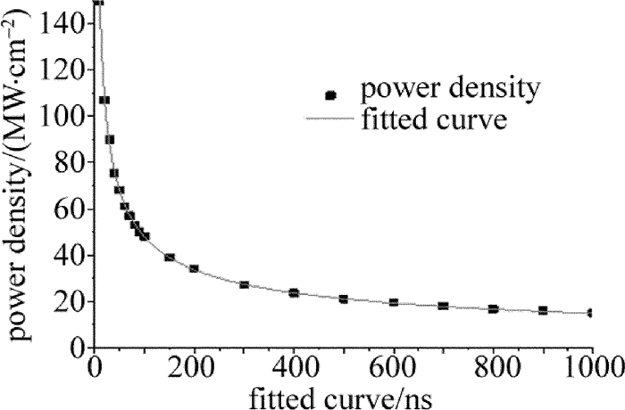
Table 3. Damage threshold of power density of in-band laserpulse width/ns power density/(MW·cm-2) 10 150 20 107 30 90 40 75.5 50 68 60 61 70 57 80 53 90 50 100 48 150 39 200 34 300 27 400 23.5 500 21 600 19.5 700 18 800 16.5 900 16 1000 15 采用表 3中的数据,利用最小二乘法进行拟合得到脉宽为ns~μs量级,波段外探测器损伤阈值曲线与公式。拟合曲线如图 4所示。
拟合公式为:
P=509.630×(τ+0.841)−0.513 (10) 结合表 3和图 4的仿真结果可以看出,波段内单脉冲激光损伤探测器的阈值曲线与波段外的趋势一致,随着激光脉宽的增大而减小,呈以脉宽为底的负指数关系,不过波段内所需的激光功率密度比波段外高约一个数量级。所以在研究脉冲激光辐照探测器温度场时应区分是否为波段内激光。因波段内单脉冲和高重频激光辐照探测时,除了阈值更高以好,探测器内部的温度场情况与波段外基本一致,故在此不再赘述重复频率和脉宽与损伤阈值和损伤程度之间的关系。
2.3 数据对比
山东师范大学的CHEN[16]等人采用脉宽为10ns、波长为1.064μm的Nd:YAG激光器,进行了6组激光辐照响应波段为8μm~12μm的HgCdTe晶体的熔化阈值实验,得到的平均熔化阈值为8.4MW/cm2,本文中波段外仿真计算结果与之基本相符。
美国海军实验室BARTOLI等人用10.6μm激光辐照响应波段为8μm~12μm的HgCdTe材料[2],得到脉宽为100ns时的损伤阈值为50MW/cm2。本文中波段内的仿真计算结果与其实验结果基本一致。
3. 结论
借助有限元软件,对HgCdTe探测器进行2维建3模,研究了ns~μs量级激光辐照HgCdTe探测器的温度场效应。结果表明,不管是波段内还是波段外的激光,在单脉冲作用下,激光脉宽越窄,损伤功率密度阈值越高,且由于波段内激光辐照时探测器存在光电效应消耗一部分激光能量,所以在脉宽相等的情况下,波段内激光损伤阈值比波段外激光损伤阈值高出约一个数量级。使用高重频脉冲激光辐照探测器时,只有在脉冲间隔小于冷却时间时才能出现温度积累效应,故得出结论:当脉宽较窄且工作在阈值功率的单脉冲激光辐照探测器时,一般只能造成探测器的局部损伤,探测器仍能正常工作,若使用长脉宽高重频激光辐照探测器,则容易出现大面积损伤而致使探测器失效。因此,在实际应用中应尽量避免高重频长脉宽激光长时间辐照探测器,以免造成探测器损伤失效。本文中未考虑熔化、燃烧波、爆轰波与热物理参量随温度的变化等,计算结果将会与实验结果存在一定程度的偏差,有待进一步改进。
-
Table 1 Thermal parameters of detector material
material density ρ /
(kg·m-3)heat capacity cp /
(J·kg-1·K-1)thermalconductivity κ /
(W·m-1·K-1)CdZnTe 5680 159 0.97 HgCdTe 7600 150 20 In 7310 237.6 82.01 epoxy 1250 1530 0.2 Si 2330 550 250 Table 2 Damage threshold of power density of off-band laser
pulse width
/nspower density/
(MW·cm-2)10 9 20 6.5 30 5.3 40 4.5 50 4 60 3.7 70 3.4 80 3.2 90 3 100 2.85 150 2.35 200 2.1 300 1.65 400 1.41 500 1.3 600 1.15 700 1.06 800 1 900 0.94 1000 0.9 Table 3 Damage threshold of power density of in-band laser
pulse width/ns power density/(MW·cm-2) 10 150 20 107 30 90 40 75.5 50 68 60 61 70 57 80 53 90 50 100 48 150 39 200 34 300 27 400 23.5 500 21 600 19.5 700 18 800 16.5 900 16 1000 15 -
[1] ZHANG F, NIU Y X, LIU N, et al. Research of temperature field and thermal stress field of CCD under laser irradiation[J]. Laser Technology, 2017, 41(3):433-437(in Chinese). http://www.wanfangdata.com.cn/details/detail.do?_type=perio&id=jgjs201703025
[2] BARTOLI F, ESTEROWITZ L, KRUER M, et al. Irreversible laser damage in irdetector materials[J]. Applied Optics, 1977, 16(11):2934-2937. DOI: 10.1364/AO.16.002934
[3] JEVITĆ M M, ŠĆEPANOVIĆ M J. Melting and solidification in laser-irradiated HgCdTe[J]. Applied Physics, 1991, A53(4):332-338. DOI: 10.1007/BF00357197
[4] GARG A, KAPOOR A, TRIPATHI K N, et al. Laser induced damage studies in mercury cadmium telluride[J]. Optics & Laser Technology, 2007, 39(7):1319-1327. http://www.sciencedirect.com/science/article/pii/S0030399206002398
[5] GARG A, KAPOOR A, TRIPATHI K N, et al. Comparative study of evolution of laser damage in HgCdTe, CdTe, and CdZnTe with nanosecond 1.06μm wavelength multiple pulses[J]. Proceedings of the SPIE, 2004, 5273:122-128. DOI: 10.1117/12.524235
[6] JIANG Zh P, LIANG T J, LU Q Sh, et al. Heat effect calculations of PC type HgCdTe detectors when irradiated by laser[J]. Applied Laser, 1995, 15(4):155-156(in Chinese). http://www.en.cnki.com.cn/Article_en/CJFDTOTAL-YYJG504.003.htm
[7] LIX Q, CHENG X A, WANG R, et al. Experimental study on the response of HgCdTe(PC) detector irradiated by laser[J]. High Power Laser & Particle Beams, 2003, 15(1):40-44(in Chinese). http://en.cnki.com.cn/article_en/cjfdtotal-qjgy200301011.htm
[8] ZHANG Y Y, ZHENG R Sh, LIU J S. Analysis of pulsed laser disturbance and damage on satellite-borne detector[J]. Journal of Elec-tronics & Information Technology, 2006, 28(9):1758-1760(in Chinese). http://www.wanfangdata.com.cn/details/detail.do?_type=perio&id=dzkxxk200609052
[9] WANG S W, LI Y, GUO L H, et al. Analysis on the disturbance of CO2 laser to long-wave infrared HgCdTe detector[J]. Journal of Infrared & Millimeter Waves, 2010, 29(2):102-104(in Chinese). http://en.cnki.com.cn/article_en/cjfdtotal-hwyh201002006.htm
[10] WANG T F, TANG W, SHAO J F, et al. Analysis of temperature and damage characteristics of HgCdTe crystal on repetition frequwency of CO2 laser[J]. Chinese Journal of Lasers, 2015, 42(2):0206006(in Chinese). DOI: 10.3788/CJL
[11] LI X L, NIU Ch H, MA M Y, et al. Research on the thermal damage of HgCdTe infrared detector under laser irradiation of 10.6μm wavelength[J]. Infrared Technology, 2016, 38(1):6-9(in Chinese). http://en.cnki.com.cn/Article_en/CJFDTotal-HWJS201601002.htm
[12] WANG Y F, TANG L B. Advances in third-generation HgCdTe devices[J].Electro-Optic Technology Application, 2009, 24(5):17-22(in Chinese). http://en.cnki.com.cn/Article_en/CJFDTotal-GDYG200905005.htm
[13] HAIRSTON A, TOBIN S P, HUTCHINS M, et al. SWIR HgCdTe 256×256 focal plane array technology at BAE systems[J].SPIE, 2006, 6295:62950I. http://d.old.wanfangdata.com.cn/NSTLHY/NSTL_HYCC026765464/
[14] TANG W. Damage mechanism of HgCdTe crystal irradiated by high repetition frequency CO2 laser[D]. Changchun: University of Chinese Academy of Sciences, 2014: 41-42(in Ch inese).
[15] DUAN X F, NIU Y X, ZHANG Ch, et al. Numerical analysis of the temperature field in HgCdTe detector by laser irradiation[J]. Journal of Optoelectronics Laser, 2003, 14(2):191-193(in Chinese). http://www.wanfangdata.com.cn/details/detail.do?_type=perio&id=CC026187411
[16] CHEN Ch S, LIU A H, SUN G, et al. Analysis of laser damage threshold and morphological changes at the surface of a HgCdTe crystal[J]. Journal of Optics, 2006, A8(1):88-92. http://www.iop.org/EJ/abstract/1464-4258/8/1/014
[17] LI X L, NIU Ch H, MA M Y, et al. Finite element simulation of damage characteristics of CCD detectors under single-laser-pulse irr-adiation[J]. Laser Technology, 2016, 40(5):730-733(in Chinese). http://en.cnki.com.cn/Article_en/CJFDTotal-JGJS201605023.htm
[18] LEI Zh, ZHANG L W, ZHANG X L, et al. Analysis and simulation of temperature field of focal plane array detector irradiated by Gaussian laser[J]. Laser Technology, 2016, 40(4):516-520(in Chinese). http://en.cnki.com.cn/Article_en/CJFDTotal-JGJS201604013.htm
[19] LU Q Sh. Laser irradiation effect of semiconductor materials and devices[M].Beijing:National Defense Industry Press, 2015:145-146(in Chinese).
-
期刊类型引用(7)
1. 孙佳鑫,钱传鹏,徐作冬,张检民,叶锡生. 长波量子阱红外探测器激光辐照损伤脉宽效应数值模拟. 激光与光电子学进展. 2024(21): 290-297 .  百度学术
百度学术
2. 胡蔚敏,王小军,田昌勇,杨晶,刘可,彭钦军. 脉宽对中红外激光带内损伤HgCdTe材料的影响. 强激光与粒子束. 2022(01): 130-137 .  百度学术
百度学术
3. 王云萍,侯军燕,袁春,康文运,陈安民,张鲁薇. 飞秒激光对多光谱滤波片的损伤阈值研究. 激光技术. 2022(05): 697-701 .  本站查看
本站查看
4. 李玉瑶,王菲,孙同同. 薄膜激光损伤阈值标定技术. 激光技术. 2021(06): 729-734 .  本站查看
本站查看
5. 白凤凤,武桂芬. 光学薄膜激光损伤阈值的智能检测研究. 激光杂志. 2020(02): 171-175 .  百度学术
百度学术
6. 周冰,贺宣,刘贺雄,李秉璇,张炎. 激光辐照非制冷微测辐射热计的理论研究. 激光技术. 2020(04): 411-417 .  本站查看
本站查看
7. 任晓东,雷武虎,曾凌清,王勇. 基于相对运动的脉冲激光辐照探测器热效应数值分析. 光子学报. 2019(01): 105-111 .  百度学术
百度学术
其他类型引用(2)


 下载:
下载:


