-
径向偏振光是一种沿径向方向偏振的非均匀偏振光束。光束传播过程中电场方向始终沿径向方向。相比于均匀线偏振光,由于其偏振分布的轴对称特性,径向偏振光具有许多奇特的性质。比如,大数值孔径聚焦下径向偏振光可得到小于衍射极限的光斑[1];且在焦平面中心将产生较强的纵向电场分量[2]。径向偏振光横向对称的电磁场可产生轴向梯度力,这一特性应用于光镊,可以实现对粒子的操控[3]。在金属切割领域,由于加工时正对金属材料的始终是强吸收的p偏振,采用径向偏振光的CO2激光器的激光切割效率大约是采用线偏振光或圆偏振光的1.5~2倍[4]。
目前产生径向偏振激光的方法较多,但总体可分为腔外法和腔内法。腔外法是指在谐振腔外采用偏振转换器件,将原有的线偏光或圆偏光转变为径向偏振光。腔内法是指在谐振腔内加入径向偏振选择器件,直接输出径向偏振光。腔外法由于光路的复杂性、较差的热稳定性以及转换效率较低等缺点不利于实现稳定的高功率激光输出。目前,腔内法有轴对称激活介质法[5]、布儒斯特窗法[6]、亚波长光栅法[7-9]等,光栅镜和轴锥镜因其较好的偏振选择特性和热稳定性被广泛的用于高功率径向偏振光的产生。但是采用集成电路制造工艺刻蚀光栅过于昂贵,而W形轴锥镜(W锥)由于便于加工、成本较低及较高热损伤阈值等优势,成为产生高功率径向偏振光的首选。
基于轴快流CO2激光器平台的亚波长光栅角向偏振光产生国内已有先例[10]。但其在高功率运行时热稳定性不佳。为改善这一现象,采用W锥作为偏振选择尾镜。运用W锥作尾镜时,光束以大角度入射于W锥表面,p偏振反射率低于s偏振反射率,当反射率之差高于2%时,即可认为仅存在s偏振在谐振腔内震荡[11]。此时得到的光束是角向偏振光,为得到径向偏振光,作者将采用参考文献[12]中介绍的腔内偏振转换方案。其原理为4个高反λ/4玻片构成两个主轴交角45°的高反半玻片。这样由尾镜方向传输的角向偏振光转化为径向偏振光,同样由输出镜方向传输而来的径向偏振光经上述玻片后,转化为角向偏振光。
传统的W锥内锥角被固定为90°[11, 13-15],但在高功率运行时由于W锥表面吸收光产生的热形变将破坏激光光束的模式,阻碍光功率的进一步提升。为此本文中研究了W锥内锥角变化对W锥热畸变和激光模式的影响,进而优化W锥的设计。
-
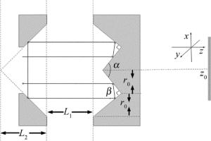
为实现径向、角向偏振选择特性,W锥对s偏振、p偏振的反射率之差需要达到2%以上。偏振选择尾镜单元由W形锥镜及其前端中空的V形镜组合而成。图 1中给出了作者提出的新型W锥的示意图。其中内锥角α可变,夹角β固定为90°。应用几何光学,轴向光束首先入射到内锥表面,经反射后到达W锥的另一锥面。由于底角β=90°,W锥两次反射后的光束总偏转角为180°,即反射后光束平行于入射光束。光束入射到前方总锥角为90°的轴棱锥后被折返180°,重新入射到W锥外侧的锥面上。最后经内锥面反射出W锥。当入射光沿轴锥镜轴线方向入射时,轴锥镜内光路关于锥镜轴线对称,从而出射光位置及方向不随α变化。
对于非磁性物质,光束在W锥锥面的反射系数为[16]:
$ {r_p} = \frac{{{n_2}\cos \theta - {n_1}\sqrt {1 - {{\left( {{n_1}{n_2}^{ - 1}\sin \theta } \right)}^2}} }}{{{n_2}\cos \theta + {n_1}\sqrt {1 - {{\left( {{n_1}{n_2}^{ - 1}\sin \theta } \right)}^2}} }} $
(1) $ {r_s} = \frac{{{n_1}\cos \theta - {n_2}\sqrt {1 - {{\left( {{n_1}{n_2}^{ - 1}\sin \theta } \right)}^2}} }}{{{n_1}\cos \theta + {n_2}\sqrt {1 - {{\left( {{n_1}{n_2}^{ - 1}\sin \theta } \right)}^2}} }} $
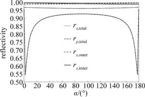
(2) 式中,n1,n2分别为空气、铜对波长为10.6μm电磁波的折射率, θ为光束的入射角。铜镜对s光、p光的反射率分别为|rs|2和|rp|2。入射的光束除去反射的部分外全被吸收,故而s,p光束的吸收率分别为1-|rs|2和1-|rp|2。假定光束沿平行于W锥旋转轴入射,内锥面入射角为90°-α/2, 外锥面入射角为α/2。而W锥前端的V形反射镜入射角为45°,不随内锥角变化改变。各反射率随α的变化如图 2所示。需要注意的是,光束在尾镜单元共经过6次反射,内、外锥面及前端锥面分别反射两次。rp, total,rs, total分别为光束在尾镜单元传播时对s偏振、p偏振的总的等效反射系数,则:rp, total=[rp(90°-α)rp(α)rp(45°)]2, rs, total=[rs(90°-α)rs(α)rs(45°)]2。从图中可以看出,总反射率曲线关于α=90°对称。在90°~110°范围内,s光, p光总反射率差值随小幅增加,这一变化有利于s偏振, p偏振选择。在此范围内,内锥面s光的反射率减小,外锥面s光的反射率增大。对应的内、外锥吸收率相应增大、减小。
入射到W锥尾镜的内环光斑可表示为[17]:
$ \begin{array}{*{20}{c}} {{E_{pl}}\left( {r,\varphi } \right) \propto }\\ {{{\left( {\frac{{\sqrt 2 r}}{{{w_0}}}} \right)}^{\left| l \right|}}{\rm{L}}_p^{\left| l \right|}\left( {\frac{{2{r^2}}}{{w_0^2}}} \right)\exp \left( { - \frac{{{r^2}}}{{w_0^2}}} \right)\exp \left( {{\rm{i}}l\varphi } \right)} \end{array} $
(3) 式中,l和p分别为角向、径向模序数,w0为光斑尺寸,Lp|l|为缔合拉盖尔多项式。激光振荡时,损耗高的横模被滤去,仅留下低损耗的模式。
通过能量守恒,可以得出内外光束电场的关系[18]:
$ \begin{array}{*{20}{c}} {E\left( {{r_2},\varphi } \right) = \exp \left( { - {\rm{i}}k{L_0}} \right) \times }\\ {\int {E\left( {{r_1},\varphi } \right)\sqrt {\frac{{{r_1}}}{{{r_2}}}} \delta \left( {{r_1} + {r_2} - 2{r_0}} \right){\rm{d}}{r_1}} } \end{array} $
(4) 式中,L0=(r2-r0)[1/tan(α/2)+tan(α/2)]为光束在内外锥面间转换时传播的距离,r0为内外锥面交线到W锥旋转轴距离,r1和r2分别为内、外锥面上点到W锥旋转轴的距离,δ(x)为δ函数,k为波数,其与波长λ的关系为k=2π/λ。
-
为研究不同α下W锥的温度形变对激光模式的影响,应用COMSOL模拟了铜为基础材料时不同内锥角α下的温度形变特性。模拟中W锥内锥半径为10mm, 考虑到实际加工时外锥与内锥底部有一定间距,模拟中此值设为2mm,外锥半径设置为10mm,即r0=11mm。谐振腔中的W锥外部实际上接近被完全固定,为此模拟中W锥底面及外边缘被设为固定面。需要注意的是,光束实际在W锥内外锥面上分别反射两次,因而实际加在每一锥面上的功率为入射功率的2倍。而总的加载到W锥尾镜上的功率为入射功率的4倍。对于透过率为30%的输出镜,当入射到输出镜上的功率为P时,反射回谐振腔中的功率为0.7P(不考虑镜片的热效应)。而到达W锥尾镜附近时,功率大致变为0.85P。这样输出功率为1000W时,对应照射到内锥面上的总光功率P1≈5666W。
图 3所示的是内锥总照射功率P1=6000W下,α分别为80°, 90°, 100°, 110°, 形变放大一定倍数时的温度分布效果图。从图中可以看出,形变后W锥的内外锥面都变为凸曲面。随α的增大,W锥的整体温度变小,最高温度依次为329K, 324K, 319K, 315K。这是由于W锥外壁面积随α而增加,这样换热的面积增加。同时W锥镜的整体温差也逐步缩小,依次为7K, 6K, 4K, 3K。这是因为W锥内锥顶部逐步向锥底部靠近,有利于内锥散热。
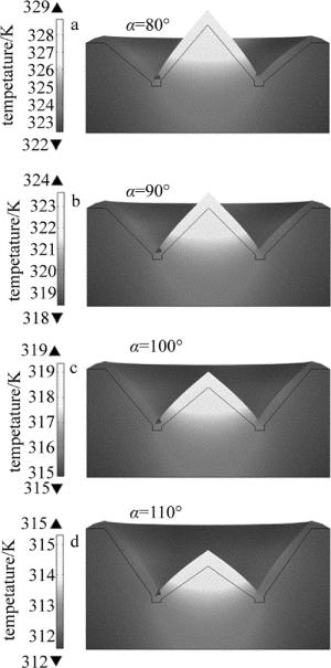
Figure 3. The variation of temperature field with α under the conditions of 6000W irradiation power and the same heat transfer
当入射功率固定时,形变量随内锥角的变化如图 4所示。图中Δd为镜面形变后各点到原曲面的距离,且规定向镜面外偏移为正。r为镜面上点到W锥镜中心轴线的距离。从图中可以看出,W锥的内、外锥面都变形为凸面镜。随α的变大,内锥面的形变量逐渐变小,而外锥面形变量则逐渐变大。内外锥面形变的这种差异使得直接选取较优的α存在一定的困难。因此,有必要将上述形变转化为对光程的影响。
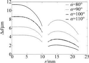
Figure 4. Under the condition of 6000W irradiation power and the same heat exchange, deformation of W-axicon at different angles
对于径向剖线无曲率的情况,应用平面镜等效展开,其光路如图 5所示。针对展开后对应镜面关于图 5所示面D对称的特点,W锥的作用可近似等效为面D处放置一反射镜。若取图 1中W锥内锥面顶点为原点,向右为z轴正方向,L1和L2如图 1所示,则与薄透镜面D对应的等效反射镜的放置位置为:z0=r0cot(α/2)+r0tan(α/2)+L1+L2。

Figure 5. Schematic diagram of the propagation of the unfolded optical path of the W-axicon mirror unit(Ⅰ:area of inner reflecting surface area; Ⅱ:area of the external reflection surface; Ⅲ:area of the V-axicon; Ⅳ:spacing area; A:the apex of the inner cone; B:outer reflection edge of the W-axicon; C:the outer edge of the V-axicon; D:equivalent symmetry plane)
传统W锥的外锥面有一定的曲率[11]。W锥的外锥面曲率半径R1尺度较大,一般选取几十米。同时激光器运行时的热膨胀等因素也将引起锥面的偏移。锥面的变化将对光束的相位产生影响。在傍轴近似下,入射到尾镜单元的光束可近似认为平行于光轴。如图 6c所示,当径向剖线有上述曲率的面与径向剖线无曲率的面偏离Δd时,由此引起的光程变化为:
$ {l_1} = \frac{{\Delta d}}{{\cos \left( {\frac{\alpha }{2}} \right)}}\left( {1 + \cos \alpha } \right) = - 2\Delta d\cos \left( {\frac{\alpha }{2}} \right) $
(5) 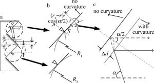
Figure 6. The cone surface diagram and schematic diagram of optical path variation, where S is the vertex of curved surface
对于仅考虑设计的径向剖线的曲率半径R1对光程的影响时,图 6a和图 6b中S点为曲面的顶点。假定距旋转轴距离为r3且平行于旋转轴的光线经内锥面反射后入射于S点,对于距旋转轴距离为r且平行于旋转轴的光线经内锥面反射后入射到外锥面,由图 6b可以得出,该入射点到径向剖线无曲率面的距离为:
$ \begin{array}{*{20}{c}} {\Delta d = {R_1} - \sqrt {R_1^2 - {{\left[ {\frac{{{r_3} - r}}{{\cos \left( {\frac{\alpha }{2}} \right)}}} \right]}^2}} \approx }\\ {\frac{{{{\left( {r - {r_3}} \right)}^2}}}{{2{R_1}{{\cos }^2}\left( {\frac{\alpha }{2}} \right)}}} \end{array} $
(6) 将(4)式代入(3)式, 由于光束在外锥面反射两次,则整个单元反射后由此引入的曲面引起的光程变化近似为:
$ \begin{array}{*{20}{c}} {\Delta {L_1} \approx 2 \times \left[ { - 2\frac{{{{\left( {r - {r_3}} \right)}^2}}}{{2{R_1}{{\cos }^2}\left( {\frac{\alpha }{2}} \right)}}\cos \left( {\frac{\alpha }{2}} \right)} \right] = }\\ { - \frac{{2{{\left( {r - {r_3}} \right)}^2}}}{{{R_1}\cos \left( {\frac{\alpha }{2}} \right)}}} \end{array} $
(7) 从(7)式可以看出,当r3=0时,整个单元的面型可近似成曲率半径为(1/2)R1cos(α/2)的球面镜。当r0 > r3 > 0时,则近似为曲率半径为(1/2)R1cos(α/2)的环型镜。
同样的处理方式用于内锥面。若内锥面径向剖线曲率半径为R2且曲面的顶点距旋转轴距离为r4,应用类似的方法可得到内锥面引入的曲率产生的光程变化:
$ {l_2} = - \frac{{\Delta d}}{{\sin \left( {\frac{\alpha }{2}} \right)}}\left( {1 - \cos \alpha } \right) = - 2\Delta d\sin \left( {\frac{\alpha }{2}} \right) $
(8) $ \Delta {L_2} \approx - \frac{{2{{\left( {r - {r_4}} \right)}^2}}}{{{R_2}\sin \left( {\frac{\alpha }{2}} \right)}} $
(9) 将模拟的内外锥面温度形变代入(5)式和(8)式转化为对光程的影响。在不考虑W锥内部光束径向偏移的条件下,结合L3=-[l1(r)+l2(2r0-r)]得到在W锥一侧反射时光程的减小量L3。如图 7所示。照射功率越高,对光程的影响越大。随着α的增大,r=0mm附近的光程减小量越大;而光束的边缘变化不一,但总体上变化幅度不及中心强烈。考虑到实际光束的半径约为7.5mm,因而对光束有较大影响的区域在0mm < r < 8.0mm。在此区域内,α太小时,外边沿的光束光程的减小量高于中心处的光束光程的减小量;而α太大时,情况与之相反。这两种情况都不利于激光模式的稳定。只有当中心、边沿的光束光程的减小量基本相等时,才能更好地保证激光模式的稳定。
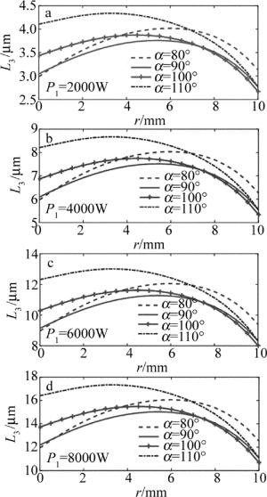
Figure 7. The variation of the optical path reductionL3 with inner cone angle αfor different irradiation power
对于等效反射面上(x, y)处一点,其到W锥旋转轴的距离为$r = \sqrt {{x^2} + {y^2}} $,将W锥锥面的曲率及温度形变都考虑进来,得到总光程减少量Ltotal:
$ \begin{array}{*{20}{c}} {{L_{{\rm{total}}}} = - 2\left[ {\frac{{{{\left( {r - {r_3}} \right)}^2}}}{{{r_1}\cos \left( {\frac{\alpha }{2}} \right)}} + \frac{{{{\left( {r - {r_4}} \right)}^2}}}{{{R_2}\sin \left( {\frac{\alpha }{2}} \right)}} + } \right.}\\ {\left. {\Delta d\left( {2{r_0} - r} \right)\cos \left( {\frac{\alpha }{2}} \right) + \Delta d\left( r \right)\sin \left( {\frac{\alpha }{2}} \right)} \right]} \end{array} $
(10) 式中,Δd(2r0-r), Δd(r)分别为外锥面和内锥面对应点处的形变量。
-
光场数值模拟基于相干光在自由空间传播的菲涅耳-基尔霍夫衍射积分[11]:
$ \begin{array}{*{20}{c}} {\mathit{\boldsymbol{g}}\left( {{x_1},{y_1}} \right)\left| {_{{H_1}}} \right. = \frac{{\exp \left( {{\text{i}}kL} \right)}}{{{\text{i}}\lambda L}}\iint_{{H_0}} {\mathit{\boldsymbol{f}}\left( {{x_0},{y_0}} \right) \times }} \\ {\exp \left\{ {\frac{{{\text{i}}k}}{{2L}}\left[ {{{\left( {{x_1} - {x_0}} \right)}^2} + {{\left( {{y_1} - {y_0}} \right)}^2}} \right]} \right\}{\text{d}}{x_0}{\text{d}}{y_0}} \end{array} $
(11) 式中,L为接收面H1与光源面H0之间的轴向距离。f(x0,y0)为面H0上复矢量电场,g(x1, y1)为H1面上复合电场。
假定起始光场始于输出镜,且将入射于W锥尾镜的光束近似为平行于旋转轴入射。模拟时将电场分为x方向、y方向,将两个方向分别运用菲涅耳-基尔霍夫衍射积分得到E1x, E1y。而后将其在W锥的等效反射面上矢量合成实际的光场。按照图 1所示路径,W锥对s偏振、p偏振的反射系数不同,光束经过W锥时,应独立对两种偏振处理。需要进行如下变换:
$ {E_p}\left( {x,y} \right) = {E_{1x}}\left( {x,y} \right)\cos \varphi + {E_{1y}}\left( {x,y} \right)\sin \varphi $
(12) $ {E_s}\left( {x,y} \right) = - {E_{1x}}\left( {x,y} \right)\sin \varphi + {E_{1y}}\left( {x,y} \right)\cos \varphi $
(13) 再将两种偏振乘上对应反射系数,而后分解到x方向和y方向,得到反射回的x方向和y方向的电场。
$ \begin{array}{*{20}{c}} {{E_x}\left( {x,y} \right) = \left[ {{r_{p,{\rm{total}}}}{E_p}\left( { - x, - y} \right)\cos \left( {\varphi + {\rm{ \mathsf{ π} }}} \right) - } \right.}\\ {\left. {{r_{s,{\rm{total}}}}{E_s}\left( { - x, - y} \right)\sin \left( {\varphi + {{180}^ \circ }} \right)} \right]\exp \left( {{\rm{i}}k{L_{{\rm{total}}}}} \right)} \end{array} $
(14) $ \begin{array}{*{20}{c}} {{E_y}\left( {x,y} \right) = \left[ {{r_{p,{\rm{total}}}}{E_p}\left( { - x, - y} \right)\sin \left( {\varphi + {\rm{ \mathsf{ π} }}} \right) + } \right.}\\ {\left. {{r_{s,{\rm{total}}}}{E_s}\left( { - x, - y} \right)\cos \left( {\varphi + {{180}^ \circ }} \right)} \right]\exp \left( {{\rm{i}}k{L_{{\rm{total}}}}} \right)} \end{array} $
(15) 式中, φ=arctan(x/y)。(14)式、(15)式中等号右方对x, y符号的变换及φ变为φ+180°是由于经过整个尾镜单元反射后,光束关于W锥的旋转轴做了一次中心对称。
任一点光强为该点x方向及y方向电场强度模平方之和,即:I=|Ex|2+|Ey|2。对于某一传输平面,其归一化光强为该面上任一点光强与该平面上最大光强的比值,即:I(z)/max(I(z))。在不计入输出镜的透射及吸收的情况下,采用Fox-Li数值迭代方法计算谐振腔的模场分布,得到图 8。图中的功率值表示内锥总照射功率P1。从模拟结果来看,α过小时,光束的外边缘逐渐向内收缩; α过大时,光束的外边缘逐渐向外展宽; α为100°和110°时,光束的稳定性较好。
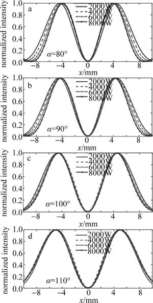
Figure 8. The normalized light intensity distribution of the resonator simulation at different angles
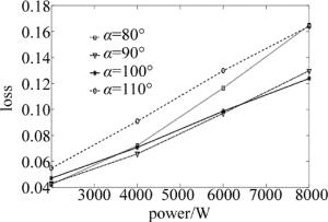
上述模场满足自再现条件:E2x(x, y)=γxE0x(x, y),E2y(x, y)=γyE0y(x, y),其中E0x(x, y), E0y(x, y)为输出镜上模式稳定后某时刻对应方向上电场,E2x(x, y)和E2y(x, y)为光束往返传输一次后的电场,γx和γy分别为电场x分量和电场y分量的本征值。其表征了谐振腔的损耗δx=1-|γx|2和δy=1-|γy|2。在不计入输出镜透射及吸收的条件下,计算了谐振腔的单程损耗。如图 9所示,光束损耗随镜片照射功率的增大逐渐增加。α=100°时的损耗明显优于110°时的损耗。结合图 8可以看出, 当照射功率增加时,α=110°时的光束逐渐向外扩展,导致其光束有部分落于镜片外部。而α=100°时的光束则向内收缩,落于镜片外的光束较少。结合以上分析α取100°为优。
传统的W锥做尾镜用于高功率激光器,其温度分布不均引起的W锥形变阻碍了激光功率的进一步提升。得益于散热效果的提升及温度分布的均匀性,α=100°的W锥相对于α=90°的W锥的形变量对光程的影响更加均匀,在产生大致相同形变的情况下获得更稳定的激光模式。
-
通过以上分析可以看出,W锥尾镜单元可以等效为有一定曲率的反射镜。通过改变内锥角可以改变W锥的温度形变特性,进而改变对光程的影响。在相同散热、入射功率条件下,增大W锥内锥角到100°时,W锥的温度形变对激光模式的影响最小,有利于进一步提高激光输出功率。
用于高功率径向偏振光的组合轴锥镜设计
Design of combined axicon for high power radial polarized light
-
摘要: 为了提升激光器径向偏振光的输出功率,改进了原有W形轴锥镜内锥角为90°的结构。为研究光束在轴锥尾镜单元的传输特性,采用几何光学分析了轴向入射下、W形轴锥镜底角为90°时,内锥角的改变对出射光的影响,发现出射光的位置及方向不发生变化;为研究轴锥镜的热畸变特性,模拟了W形轴锥镜的温度形变,可知内锥角变大时整体温度变小且分布更加均匀。结果表明,随着内锥角的变大,光束中心的光程减少量相对于光束边沿的光程减少量增大;采用Fox-Li数值迭代法模拟了引入上述形变后谐振腔的激光模式,得出在内锥角为100°时温度形变对光束模式的影响最小。通过对W形轴锥镜温度形变的研究,可为优化W形轴锥镜的设计提供参考。Abstract: In order to increase the output laser power of radically polarized light, a W-axicon was improved by changing the internal cone angle. For a W-axicon with the external cone angle of 90°, the position and direction of the reflected light will not change for different internal cone angles through analysis according to geometrical optics. In order to study the thermal distortion characteristics of the axis cone mirror, temperature deformation simulation was conducted. The result shows that the overall temperature becomes smaller and the distribution is more uniform when the inner cone angle increases. As the inner cone angle becomes larger, the decrease in the optical path of the beam center increases with respect to the decrease in the optical path edge. The Fox-Li numerical iteration was used to simulate the laser mode of the resonator. It is found that the effect of temperature deformation on the laser mode is least when the inner cone angle is 100°. The study of W-axicon temperature deformation can provide reference for W-axicon design.
-
Key words:
- optical design /
- temperature deformation /
- geometric optics /
- combined axicon /
- radially polarized light /
- laser mode
-
Figure 5. Schematic diagram of the propagation of the unfolded optical path of the W-axicon mirror unit(Ⅰ:area of inner reflecting surface area; Ⅱ:area of the external reflection surface; Ⅲ:area of the V-axicon; Ⅳ:spacing area; A:the apex of the inner cone; B:outer reflection edge of the W-axicon; C:the outer edge of the V-axicon; D:equivalent symmetry plane)
-
[1] DORN R, QUABIS S, LEUCHSS G. Sharper focus for a radially polarized light beam[J]. Physical Review Letters, 2003, 91(23):233901. doi: 10.1103/PhysRevLett.91.233901 [2] LIU Y, CLINE D, HE P. Vacuum laser acceleration using a radially polarized CO2 laser beam[J]. Nuclear Instruments and Methods in Physics Research Section, 1999, A424(2):296-303. [3] ZHAN Q, LEGER J. Focus shaping using cylindrical vector beams[J]. Optics Express, 2002, 10(7):324-331. [4] NIZIEV V G, NESTESTEROV A V. Influence of beam polarization on laser cutting efficiency[J]. Journal of Physics, 1999, D32(13):1455-1461. [5] YONEZAWA K, KOZAWA Y, SATO S. Generation of a radially polarized laser beam by use of the birefringence of a c-cut Nd:YVO4 crystal[J]. Optics Letters, 2006, 31(14):2151-2153. doi: 10.1364/OL.31.002151 [6] KOZAWA Y, SATO S. Generation of a radially polarized laser beam by use of a conical Brewster prism[J]. Optics Letters, 2005, 30(22):3063-3065. doi: 10.1364/OL.30.003063 [7] MOSER T, GLUR H, ROMANO V, et al. Polarization-selective grating mirrors used in the generation of radial polarization[J]. Applied Physics, 2005, B80(6):707-713. [8] AHMED M A, VOSS A, VOGEL M M, et al. Multilayer polarizing grating mirror used for the generation of radial polarization in Yb:YAG thin-disk lasers[J]. Optics Letters, 2007, 32(22):3272-3274. doi: 10.1364/OL.32.003272 [9] MOSER T, AHMED M A, PIGEON F, et al. Generation of radially polarized beams in Nd:YAG lasers with polarization selective mirrors[J]. Laser Physics Letters, 2004, 1(5):234-236. doi: 10.1002/lapl.200410056 [10] LU L J, LI B, WANG Y Q, et al.Generation of azimuthally polarized beam based on hybrid grating mirror[J]. Laser Technology, 2015, 39(5):585-589(in Chinese). [11] ENDO M. Development of an optical resonator with conical retroreflector for generation of radially polarized optical beam[C]//Lasers and Applications in Science and Engineering. San Jose, USA: International Society for Optics and Photonics, 2008: 687207. [12] WANG Y Q, LI B, YANG Y, et al. A resonant cavity structure for producing radially polarized laser: CN104319608A[P].2015-01-28(in Chinese). [13] ENDO M, YAMAGUCHI S, UCHIYAMA T, et al. Numerical simulation of the W-axicon type optical resonator for coaxial slab CO2 lasers[J]. Journal of Physics, 2001, D34(1):68-77. [14] ENDO M. Numerical simulation of an optical resonator for generation of a doughnut-like laser beam[J]. Optics Express, 2004, 12(9):1959-1965. doi: 10.1364/OPEX.12.001959 [15] ENDO M. Doughnut like beam generation by a W-axicon resonator with variable geometry[J]. Japanese Journal of Applied Physics, 2007, 46(2R):593-596. [16] YU D Y, TAN H Y.Engineering optics[M]. 3rd ed.Beijing:Machinery Industry Press, 2011:303-304(in Chinese). [17] HODGSON N, WEBER H. Optical resonators[M]. New York, USA:Springer, 1997:168. [18] EHRLICHMANN D, HABICH U, PLUM H D. Diffusion-cooled CO2 laser with coaxial high frequency excitation and internal axicon[J]. Journal of Physics, 1993, D26(2):183-191. -


 网站地图
网站地图

 下载:
下载:
