-
相位测量轮廓术中,硬件系统的标定是完成像平面和投影平面像素坐标到空间3维坐标的转换的必要步骤,其标定精度决定了系统的测量精度[1-3]。硬件系统标定包括摄像机和投影仪的内外参量矩阵标定,目前摄像机标定方法日趋成熟,典型的是BOUGUET等人建立的MATLAB相机标定工具箱,由于考虑了镜头的2阶径向和切向畸变,相机的标定精度可以达到0.03pixel[4-6]。为了使用成熟的相机标定算法计算投影仪的内外参量矩阵,可以把投影仪看作是一个逆向的相机[7-9],投影仪分别向标定板投射垂直和水平的正弦相移光栅条纹图像,根据标定板角点在水平和垂直方向的展开相位值确定角点在投影图像的像素坐标,得到用于标定的标靶图像(digital micro-mirror device,DMD)。在实际测量中,摄像机采集的变形光栅条纹图像会受到投影仪-摄像机γ非线性和环境噪声等因素的影响,因此相位误差不可避免地被引入了。为了减小环境噪声和γ非线性因素的对系统测量精度的影响,LI等人假设相位的主要误差的来源是投影仪的γ非线性,利用查表法使相位精度提高了5.6倍[10],该方法需要做大量实验得到误差参量表,并且查表过程耗时较长。ZHOU等人建立了环境光和相位误差之间关系的模型,使得相位误差明显减小,但是该种方法需要投射全白和全黑图案到均匀平面白板上以确定变形条纹图像的平均灰度和调制度,在噪声来源复杂的工业生产现场,比如锻造和焊接的工业生产现场,此种方法是不实用的[11]。LEI等人提出了多频反相位误差法补偿相位的非线性误差,投影仪将两套初相位相差π/4的相移光栅条纹图像投射到物体表面,将两套光栅条纹图像的包裹相位取平均值,可以达到抑制γ非线性误差的目的[12],但是此方法需要投射两倍数量的光栅条纹图像,因此测量效率较低。
-
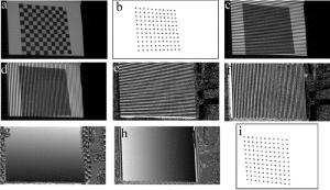
投影仪将垂直和水平的正弦相移光栅条纹图像分别投射到棋盘格表面,和投影仪呈一定角度的摄像机获取变形的光栅条纹图像,并分别计算垂直和水平方向的展开相位。根据标定板的每个角点在水平和垂直方向的展开相位值确定角点在投影图像的像素坐标,得到用于标定的DMD图像。将标定板放置于相对于投影仪的不同位置,重复以上步骤,得到多于3幅标靶图像,利用MATLAB相机标定工具箱即可得到投影仪的内外参量矩阵。黑白棋盘格的黑色和白色区域对白光的反射率相差很大,会造成变形条纹图像中黑色区域的灰度值过低,从而无法完成相位展开。红蓝棋盘格对白光的反射率相近[7, 13],因此本文中采用红蓝棋盘格作为标定板工具。棋盘格的标定流程如图 1所示。图 1a是红光照射下的红蓝棋盘格图像; 用MATLAB相机标定程序得到该棋盘格的角点坐标如图 1b所示; 投影仪将水平和竖直的相移光栅条纹图像投射到红蓝棋盘格表面,摄像机采集变形光栅条纹图像,其中一幅水平和竖直的条纹图像分别如图 1c和图 1d所示; 再根据摄像机采集到的条纹图像计算水平的和竖直方向的包裹相位,分别如图 1e和图 1f所示; 然后根据包裹相位计算出水平和竖直方向的展开相位,分别如图 1g和图 1h所示。假设棋盘格某个角点坐标为(uc, vc),由于MATLAB标定程序计算得到角点坐标(uc, vc)为亚像素级,利用线性插值得到每个角点在水平和竖直方向的展开相位值,该点在水平和竖直方向的相位展开值分别记为Φ1(uc, vc)和Φ2(uc, vc),则该角点在DMD图像中的像素坐标(up, vp)为:
$ {u_{\rm{p}}} = \frac{{{\mathit{\Phi }_1}\left( {{u_{\rm{c}}},{v_{\rm{c}}}} \right) \times {W_1}}}{{2{\rm{ \mathsf{ π} }}{N_1}}} $
(1) $ {v_{\rm{p}}} = \frac{{{\mathit{\Phi }_2}\left( {{u_{\rm{c}}},{v_{\rm{c}}}} \right) \times {W_2}}}{{2{\rm{ \mathsf{ π} }}{N_2}}} $
(2) 式中,W1和W2分别是投影仪在水平和竖直方向的分辨率,N1和N2分别是投影光栅条纹图像在水平和垂直方向周期数。根据(1)式和(2)式计算得到棋盘格各角点在投影图像中的像素坐标如图 1i所示,图 1i就是用于投影仪标定的DMD图像。
(1) 式和(2)式中,在W1,W2,N1和N2一定的情况下,DMD图像坐标误差dup和dvp取决于展开相位误差dΦ1(uc,vc)和dΦ2(uc, vc):
$ {\rm{d}}{u_{\rm{p}}} = \frac{{{\rm{d}}{\mathit{\Phi }_1}\left( {{u_{\rm{c}}},{v_{\rm{c}}}} \right) \times {W_1}}}{{2{\rm{ \mathsf{ π} }}{N_1}}} $
(3) $ {\rm{d}}{v_{\rm{p}}} = \frac{{{\rm{d}}{\mathit{\Phi }_2}\left( {{u_{\rm{c}}},{v_{\rm{c}}}} \right) \times {W_2}}}{{2{\rm{ \mathsf{ π} }}{N_2}}} $
(4) 因此, 要减小DMD图像的角点坐标像素误差,必须减小水平和垂直方向的展开相位误差。
-
在相位测量轮廓术中,投影光栅条纹图像强度分布如下式所示:
$ {I_n}\left( {x,y} \right) = A + B\cos \left( {2{\rm{ \mathsf{ π} }}fx + 2{\rm{ \mathsf{ π} }}n/N} \right) $
(5) 式中,A和B是常数,f是频率,x是投影图像像素坐标的横坐标,n是索引数,N是相移图像的总数量。投影仪与相机的γ非线性效应可被整体视为系统的γ值[11],投影光栅条纹图像被物体表面调制后,若CCD采集到的变形光栅图像没有发生饱和,变形光栅条纹图像仍呈现正弦性,采集到的图像中某像素点的光强值为[14]:
$ I_n^\gamma = \alpha {\left[ {M + Q\cos \left( {\varphi + {\delta _n}} \right)} \right]^\gamma } $
(6) 式中,γ即系统的γ非线性值,α是常数,φ为畸变光栅的相位主值,M和Q分别是图像的平均强度和调制度,δn是相移量。
(6) 式可以变换为:
$ I_n^\gamma = \alpha {M^\gamma }{\left[ {1 + p\cos \left( {\varphi + {\delta _n}} \right)} \right]^\gamma } $
(7) 式中,p=Q/M。
根据广义二项式定理将(7)式展开:
$ I_n^\gamma = \alpha {M^\gamma }\sum\limits_{m = 0}^\infty {\left[ {{\rm{C}}_\gamma ^m{p^m}{{\cos }^m}\left( {\varphi + {\delta _n}} \right)} \right]} $
(8) 式中,m是根据广义二次项定理展开的各个序列项,是从0到无穷大的整数, Cγm表示组合。
再根据余弦降幂公式,(8)式可以改写为:
$ I_n^\gamma = 0.5{B_0} + \sum\limits_{k = 1}^\infty {\left\{ {{B_k}\cos \left[ {k\left( {\varphi + {\delta _n}} \right)} \right]} \right\}} $
(9) 式中,B0是直流分量系数,Bk(k≥2)是高次谐波的系数。
$ {B_k} = 2{M^\gamma }\sum\limits_{s = 0}^\infty {{b_{k,s}}} $
(10) $ {b_{k,s}} = {\left( {0.5p} \right)^{2s + k}}{\rm{C}}_\gamma ^{2s + k}{\rm{C}}_{2s + k}^s $
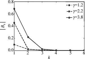
(11) 式中,k, s均为非负整数。当γ是整数,且k≥1,当k>γ时,Bk=0;当γ是非整数时,Bk是一个无限序列之和且收敛。当p=0.8(在有环境光的条件下,p < 1),γ分别取1.2,2.2和3.8时,|Bk|如图 2所示(取bk, s前100项之和)。从图 2可见,|Bk|随k值的增大迅速减小, |Bk|和k均无量纲。
一般情况下,系统的γ值并不是一个整数,因此变形光栅条纹图像中存在高次谐波(Bk≠0),导致相位误差的存在。当γ分别取1.2,2.2和3.8时,B5/B1分别小于0.0078,0.00034和0.000083,5次谐波系数相对于一次谐波系数较小,因此本文中考虑的最高谐波为4次谐波。将${\delta _{\rm{n}}} = \frac{{2{\rm{ \mathsf{ π} }}\left( {n - 1} \right)}}{4}$代入(9)式, 得到Inγ(n=1, 2, 3, 4)的表达式:
$ \begin{array}{*{20}{c}} {I_n^\gamma \approx 0.5{B_0} + \sum\limits_{k = 1}^4 {\left\{ {{B_k}\cos \left[ {k\left( {\varphi + } \right.} \right.} \right.} }\\ {\left. {\left. {2{\rm{ \mathsf{ π} }}\left( {n - 1} \right)/4} \right]} \right\}} \end{array} $
(12) 采用四步相移法计算截断相位,假设4幅变形光栅条纹图像的平均强度和调制度相等,则实际的相位主值为:
$ \varphi ' = \arctan \left[ {\frac{{{B_1}\sin \varphi - {B_3}\sin \left( {3\varphi } \right)}}{{{B_1}\cos \varphi + {B_3}\cos \left( {3\varphi } \right)}}} \right] $
(13) 理想的截断相位为:
$ \varphi = \arctan \left( {\frac{{\sin \varphi }}{{\cos \varphi }}} \right) $
(14) 由(13)式和(14)式可知,引起四步相移法非线性误差的主要因素是3次谐波。相位误差为:
$ \Delta \varphi = \varphi - \varphi ' = \arctan \left[ {\frac{{\frac{{{B_3}}}{{{B_1}}}\sin \left( {4\varphi } \right)}}{{1 + \frac{{{B_3}}}{{{B_1}}}\cos \left( {4\varphi } \right)}}} \right] $
(15) 式中,B1和B3分别是变形光栅条纹图像一次谐波和三次谐波的系数,Δφ是一个周期型函数,且周期是截断相位周期的1/4。因此对于四步相移法,变形光栅条纹图像的三次谐波引起频率为截断相位频率4倍的周期性误差。假设近似的相位误差补偿值为:
$ \Delta \varphi ' = \arctan \left[ {\frac{{\frac{{{B_3}}}{{{B_1}}}\sin \left( {4\varphi '} \right)}}{{1 + \frac{{{B_3}}}{{{B_1}}}\cos \left( {4\varphi '} \right)}}} \right] $
(16) 式中,φ′是由(13)式计算得到实际的相位主值,由(10)式和(11)式可知,Bk随k值的增大迅速减小,因此B3/B1是一个相对较小的值,当γ=2.2,p=0.8时,由(10)式、(11)式求得B3/B1=0.0063,代入(16)式~ (17)式得到|Δφ′-Δφ| < 7.94×10⁻⁵rad,|Δφ|≤0.0063rad;当γ=3.8时,p=0.8时,B3/B1=0.0879,|Δφ|≤0.0879rad,由(16)式~(17)式可得|Δφ′-Δφ| < 0.0175rad,因此当γ位于此区间内时,可认为下式成立:
$ \arctan \left[ {\frac{{\frac{{{B_3}}}{{{B_1}}}\sin \left( {4\varphi '} \right)}}{{1 + \frac{{{B_3}}}{{{B_1}}}\cos \left( {4\varphi '} \right)}}} \right] \approx \frac{{\frac{{{B_3}}}{{{B_1}}}\sin \left( {4\varphi '} \right)}}{{1 + \frac{{{B_3}}}{{{B_1}}}\cos \left( {4\varphi '} \right)}} $
(17) 因此Δφ′是一个周期函数且波动幅值约为B3/B1,由(10)式、(11)式可知,B3和γ值以及p值有关,在γ和p未知的情况下,B3/B1的值就是周期函数相位误差波动的幅值。随着γ值的增大,由(17)式计算的相位误差补偿精度有所降低,但是仍然能有效地去除非线性相位误差。为了改善视觉效果,普通的商用投影仪和摄像机的γ值一般大于1,太高的γ值会使画面过暗,美国国家电视系统委员会推荐的γ值为2.2[15],而投影仪的非线性是测量硬件中引起非线性误差的主要因素[16],因此在实际测量中测量系统的γ值位于一定的范围内,由(16)式即可得到近似的相位误差补偿值Δφ′。
-
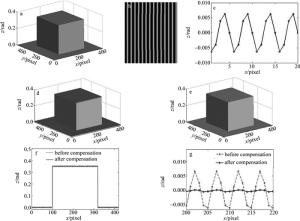
计算机软件生成一个方形物体如图 3a所示,采用标准的四步相移法,按照(6)式模拟生成4幅变形光栅条纹图像,周期为20pixel,其中一幅如图 3b所示,此时γ=2.2,α=0.5,M=1,N=0.8。利用标准四步相移法求截断相位并展开,方形物体的相位高度如图 3d所示,在物体表面可见明显的周期性的误差分布,这是由γ非线性引起的相位误差波动。相位误差波动幅度(B3/B1)约为0.0063rad,如图 3c所示,相位误差波动周期为5pixel,相位误差波动频率是截断相位频率的4倍。采用(16)式计算相位误差补偿值,相位补偿后物体相位高度如图 3e所示,物体表面明显光滑,周期性误差幅值明显减小。图 3f是图 3d和图 3e第257行对比图,图 3g是相位补偿前后的误差对比图,由γ非线性引起的周期相位误差幅值由0.0063rad降低到3.54×10⁻⁴rad。
-
为了验证该方法的有效性,在实验室对红蓝棋盘格标定板进行了相位展开及相位误差补偿实验。红光照射下的红蓝棋盘格如图 4a所示,将4幅初相位相差90°正弦光栅条纹图像投射到其表面,和投影仪呈一定角度的摄像机采集到的1幅变形光栅条纹图像如图 4b所示,图 4b的灰度图像如图 4c所示,红蓝棋盘格的红色和蓝色区域对白光反射率相近,有利于求解截断相位和展开相位。采用四步相移法计算截断相位并展开,展开相位如图 4d所示,可见展开相位表面有明显的周期性的误差波动。为了清晰地显示展开相位的周期性误差,截取展开相位的局部(26×31)如图 4f所示,展开相位误差波动幅度(B3/B1)约为0.07rad,如图 4h所示。将B3/B1代入(16)式得到近似的相位误差补偿值Δφ′,补偿后的展开相位如图 4e所示,补偿后的展开相位局部(26×31)如图 4g所示,图 4d和图 4e的第100行对比图如图 4i所示,可见由投影仪-摄像机的γ非线性引起的周期性相位误差得到明显的消除,补偿后相位展开平面的均方根误差(root mean square,RMS)从0.0836rad降低到0.0218rad。本次实验中,摄像机镜头畸变和红蓝棋盘格的反射率差异等因素也会引起相位误差,本方法主要减小由摄像机-投影仪γ非线性引起的相位误差。
本次实验中,投影仪的分辨率为1024×768,摄像机的分辨率为960×1280。误差补偿前后,相位展开平面的周期性误差波动的最大值分别小于0.1rad和0.035rad,如图 4d、图 4e和图 4i所示。因此,误差补偿前后,利用线性插值求得棋盘格角点的亚像素级坐标在水平和竖直方向的展开相位值的最大误差也分别小于0.1rad和0.035rad。本次实验是对竖直光栅的展开相位进行补偿,竖直光栅展开相位决定了棋盘格角点在DMD图像中的纵坐标vp,投影仪在竖直方向的分辨率W2=1024,投影条纹周期数N2=48,按照(4)式计算标定板角点坐标误差|dvp|,最大值约由补偿前的0.3pixel降低到0.1pixel。
-
摄像机和投影仪的γ非线性使变形光栅条纹图像存在高次谐波,引起展开相位平面的周期性误差,红蓝棋盘格角点在DMD图像中的坐标精度会受到相位误差的影响而降低。本文中建立了周期性误差和截断相位之间的数学模型,并在此模型的基础上补偿展开相位。实验证明:相位补偿后棋盘格平面展开相位展开平面的RMS从0.0836rad下降到0.0218rad;由γ非线性引起的棋盘格角点在DMD图像中的像素坐标的最大误差值约从补偿前的0.3pixel低到0.1pixel。
投影仪标定中的相位误差补偿
Phase compensation for projector calibration
-
摘要: 为了减小由投影仪-摄像机γ非线性引起的红蓝棋盘格标定板相位误差,分析了非线性相位误差的产生原因和表现特征,建立了非线性相位误差和相位主值之间的数学模型,由该模型得到相位误差补偿矩阵并修正展开相位;同时采用MATLAB仿真并结合相关试验对该算法进行了验证。结果表明,误差补偿后棋盘格平面展开相位的均方根误差从0.0836rad下降到0.0218rad;由γ非线性引起的棋盘格角点在标靶图像中像素坐标的最大误差值约从补偿前的0.3pixel降低到0.1pixel。该方法有效减小了由投影仪-摄像机γ非线性引起相位误差,提高了标靶图像的角点坐标精度。Abstract: In order to overcome the phase error caused by γ nonlinearity of projector-camera pair about red/blue checkerboard in the projector calibration processing, the reason and the characteristics of nonlinear phase error were studied and the mathematical model between the nonlinear phase error and the wrapped phase was established. Based on the mathematical model, the phase error compensation matrix was obtained to correct the unwrapped phase. The experimental results show that the root mean square of the unwrapped phase after compensation is decreased from 0.0836rad to 0.0218rad. The maximum pixel error of grid corner caused by γ nonlinearity of the projector-camera pair at digital micro-mirror device (DMD) image is approximately reduced from 0.3pixel to 0.1pixel after phase compensation. The proposed method is useful to decrease the periodic phase error caused by γ nonlinear of the projector-camera paird and obtain higher accuracy coordinates of the red/blue checkerboard grid corner at DMD images.
-
Figure 1. Acquisition flow chart of projector DMD image
a—red/blue checkerboard with red light illumination b—grid corner of red/blue checkerboard c—horizontal fringe patterns d—vertical fringe patterns e—horizontal wrapped phase maps f—vertical wrapped phase maps g—horizontal unwrapping phase maps h—vertical unwrapping phase maps i—DMD image
Figure 4. Experimental results
a—red/blue checkerboard with red light illumination b—the colorful image of the deformed pattern c—the grayscale image of Fig. 4b d—unwrapped phase before compensation e—unwrapped phase after compensation f—zoom-in view of unwrapped phase before compensation g—zoom-in view of unwrapped phase after compensation h—fluctuation of phase error i—comparison of the 100th row in Fig. 4d and Fig. 4e
-
[1] YONEYAMA S, MORIMOTO Y, FUJIGAKI M, et al. Phase-measuring profilometry of moving object without phase-shiftingdevice[J]. Optics and Lasers in Engineering, 2003, 40(3):153-161. doi: 10.1016/S0143-8166(02)00100-8 [2] BEN-HAMADOU A, SOUSSEN C, DAUL C, et al. Flexible calibration of structured-light systems projecting point patterns[J].Computer Vision and Image Understanding, 2013, 117(10):1468-1481. doi: 10.1016/j.cviu.2013.06.002 [3] DIN I, ANWAR H, SYED I, et al. Projector calibration for pattern projection systems[J]. Journal of Applied Research and Technology, 2014, 12(1):80-86. doi: 10.1016/S1665-6423(14)71608-6 [4] HANSARD M, EVANGELIDIS G, PELORSON Q, et al. Cross-calibration of time-of-flight and colour cameras[J]. Computer Vision and Image Understanding, 2015, 134:105-115. doi: 10.1016/j.cviu.2014.09.001 [5] BOUGUET J Y.Camera calibration toolbox for matlab[EB/OL]. (2015-10-14)[2016-10-2]. http://www.vision.caltech.edu/bouguetj/calib_doc/. [6] LEAARDA-SAENZ R, BOTHE T, JUPTNER W. Accurateprocedure for the calibration of a structured light system[J]. Optical Engineering, 2004, 43(2):464-471. [7] CHEN Y J, WANG K Q, ZUO W M, et al. A novel projector calibration method based on improved two-frequency grating projection[J]. ICIC Express Letter, 2012, B3(1):71-76. [8] ZHANG S, HUANG P.Novel method for structured light system calibration[J]. Optical Engineering, 2006, 45(8):083601. doi: 10.1117/1.2336196 [9] LIU Sh T, LUO H F, CHEN X M, et al. Review of calibration method for structured light measurement[J].Laser Technology, 2015, 39(2):252-258(in Chinese). [10] LI Z W, SHI Y S, WANG C J, et al. Accurate calibration method for a structured light system[J]. Optical Engineering, 2008, 47(5):053604. doi: 10.1117/1.2931517 [11] ZHOU P, LIU X R, HE Y, et al. Phase error analysis and compensation considering ambient light for phase measuring profilometry[J]. Optics and Lasers in Engineering, 2014, 55(7):99-104. [12] LEI Z K, WANG C L, ZHOU C L. Multi-frequency inverse-phase fringe projection profilometry for nonlinear phase error compensation[J]. Optics and Lasers in Engineering, 2014, 66(3):249-257. [13] CHENG R. Research and design of 3-D shape measurement system based on digital fringe projection[D]. Wuhan: Huazhong University of Science & Technology, 2013: 16-17(in Chinese). [14] HOANG T, PAN B, NGUYEN D, et al. Generic gamma correction for accuracy enhancement in fringe-projection profilometry[J]. Optics Letters, 2010, 35(12):1992-1994. [15] HEY H, CAO Y P, ZHONG L J, et al. Improvement on measuring accuracy of digital phase measuring profilometry by frequency filtering[J]. Chinese Journal of Lasers, 2010, 37(1):220-224(in Chinese). doi: 10.3788/JCL [16] ZHANG S, YAU S T. Generic non-sinusoidal phase error correction for three-dimension shape measurement using a digital video projector[J]. Applied Optics, 2007, 46(1):36-43. doi: 10.1364/AO.46.000036 -


 网站地图
网站地图


 下载:
下载:


