-
Rochon棱镜发明于1783年,通常由两块光轴相互垂直的冰洲石晶体直角棱镜胶合而成[1-2],由于冰洲石晶体具有光学性能稳定、双折射率大[3-5]、透射光谱范围宽等特点[6-7],所以以其为原料制成的Rochon棱镜具有消光比高(优于10-5)、透射比大(大于87%)[8-9]、抗损伤域值高等一系列优点,是当前激光应用技术中广泛使用的偏光分束棱镜[10-12]。Rochon棱镜可以正向使用,也可以反向使用,但反向使用时,消光比会下降,对于会聚光束或发散光束,锥光干涉会引起反向消光比的下降,但对于平行光束,反向通过Rochon棱镜后,实验中发现传播方向不变的一束光的消光比仍然比正向应用时低。作者对此进行了系统的理论分析,给出了这一现象的一种合理解释,并通过实验对理论分析结果进行了验证,本文中的研究成果可为Rochon棱镜的设计制作和正确使用提供必要的参考。
-
Rochon棱镜正向和反向应用时,光在棱镜中传播的光路分别如图 1a和图 1b所示。图中S为棱镜的结构角,i为垂直于棱镜端面的入射光线,h为胶合层的厚度。对于正向使用的Rochon棱镜,由图 1a可知,入射自然光在棱镜的第一部分及胶合层中传播时,并不起偏,当到达胶合层与棱镜第二部分的分界面时才分成o光和e光;对于反向使用的Rochon棱镜,入射自然光进入棱镜的第二部分后,便被分成o光和e光,但二者传播方向一致,在棱镜第二部分和胶合层界面处,o光和e光传播方向分离,经棱镜第一部分出射。实验表明,棱镜反向使用时,o光的消光性能显著下降。
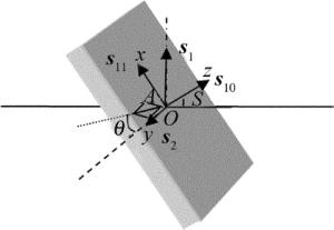
为了解释棱镜反向使用时o光消光比下降的原因,先对胶合层进行分析。由于胶合层采用的胶合剂为各向同性介质,在存在应力的情况下由于光弹效应会变为各向异性介质[13-14],胶合层固化后,胶合层内任意一点A的受力模型可用图 2表示。
图 2中建立直角坐标系O-xyz,Ox和Oy轴位于胶合层所在的平面内,坐标原点O在A点上。A点在x, y, z方向受到的应力分别用s11, s2, s10表示,s1和s2分别为垂直于o光传播方向的最大主应力和最小主应力,其中s2为s11和s10的矢量和。由图 1可知,胶合层法线与光传播方向的夹角与棱镜结构角S相等,即s10与光的传播方向的夹角为S(如图 2所示),所以s1=s10sinS+s11cosS。另外假设胶合层内所有点的受力情况都与A点相同,由两向应力-光学定律得[15]:
$ {R_t} = kt({\mathit{\boldsymbol{s}}_1} - {\mathit{\boldsymbol{s}}_2}) $
(1) 式中,Rt为光矢量方向平行于s1和s2的两束线偏振光分量通过胶合层时产生的光程差,Rt为t的函数,t为沿光线传播方向材料的有效厚度,满足$ t = \frac{h}{{\cos S}} $,k为与胶合剂材料有关的应力-光学常数。所以,胶合层对于入射光来讲,相当于通过延迟量为$ \Delta = {R_t}\frac{{2{\rm{ \mathsf{ π} }}}}{\lambda } $的相位延迟器,假设s2与o光光矢量之间的夹角为θ,Rochon棱镜反向使用时,满足[16]:
$ \begin{array}{c} \left[ \begin{array}{l} {E_x}\\ {E_y} \end{array} \right] = \left[ {\begin{array}{*{20}{c}} {{{\rm{e}}^{{\rm{i}}\mathit{\Delta }}}}&0\\ 0&1 \end{array}} \right]\left[ {\begin{array}{*{20}{c}} {\cos \theta }&{\sin \theta }\\ { - \sin \theta }&{\cos \theta } \end{array}} \right]\left[ \begin{array}{l} 1\\ 0 \end{array} \right] = \\ \left[ \begin{array}{l} {{\rm{e}}^{{\rm{i}}\mathit{\Delta }}}\cos \theta \\ - \sin \theta \end{array} \right] \end{array} $
(2) 式中, Ex表示光矢量在x方向上的分量,Ey表示光矢量在y方向上的分量。由此可见,线偏振光经胶合层等效的相位延迟器后,变为椭圆偏振光。上面的理论分析同样适用于e光,即o光和e光经胶合层后都变成了椭圆偏振光。由光在晶体中传播的知识可知[17],在单轴晶体中,传播的e光只能是平面偏振光,所以Rochon棱镜无论正向使用还是反向使用,e光都具有较高的消光比。对于o光,棱镜正向使用时,从胶合层出射的光要经过棱镜的第二部分,而在棱镜的第二部分中,晶体光轴与光的传播方向不一致,因此o光只能是平面偏振光,所以消光比较高,而反向使用时,从胶合层出射的光要经过棱镜的第一部分,但在棱镜的第一部分中,晶体光轴与光的传播方向一致,因此o光可以是平面偏振光、椭圆偏振光或圆偏振光,所以从胶合层出射的椭圆偏振光会直接经棱镜第一部分出射,即出射o光为椭圆偏振光,导致消光比会降低。
-
Rochon棱镜o光消光比测试及偏振态的检测光路如图 3所示。光源采用He-Ne激光器,由激光器发出的光经扩束透镜和准直透镜后,变为准直光束,垂直与入射Rochon棱镜,测试消光比时,不加入λ/4波片,o光直接进入检偏器,然后通过衰减器进入CCD探测器,检偏器采用优质格兰-泰勒棱镜,其消光比优于10-7,利用计算机对CCD采集到的数据进行分析。检测o光偏振态时,光路中加入λ/4波片,旋转λ/4波片,使其快轴与消光比测试时检测到的光强最大(最小)方位一致,再旋转检偏器,测量消光比,实验结果如表 1所示。
Table 1. Parameters of extinction and polarization detection
forward reverse extinction ratio (collimating beam) 1.14×10⁻⁵ without λ/4 wave-plate with λ/4 wave-plate 2.93×10⁻³ 5.72×10⁻⁵ 由表 1可知,在准直光束照射下,Rochon棱镜反向消光比远小于正向,但加入λ/4波片后,反向消光比增大,由此可见,棱镜反向使用时,出射光中含有椭圆偏振光的成分,这与理论分析的一致,但是与正向使用的棱镜相比较,消光比仍然较低,其原因是上面分析时,将胶合层受力后看成单轴晶体,各点受力情况均相同所致。
-
通过对Rochon棱镜胶合层受到的应力进行分析,得出由于胶合层光弹效应的影响,平面偏振光经过后会变成椭圆偏振光,结合晶体光学的相关知识,从理论上解释了Rochon棱镜反向使用时,o光消光比下降的原因,并设计实验,对理论分析的结果进行了验证。本文中相关的理论和实验研究成果可为Rochon棱镜的设计和应用提供有益的参考。
Rochon棱镜反向使用消光比
Extinction ratios of reverse Rochon prisms
-
摘要: 为了研究Rochon棱镜反向使用消光比特性,采用分析棱镜胶合剂中光弹效应的方法,对Rochon棱镜正、反向使用时消光比进行了分析,并设计了实验,从理论和实验上对平行光反向通过Rochon棱镜时消光比下降的原因进行了研究。结果表明,当平行光正向通过Rochon棱镜时,消光比为1.14×10⁻⁵;反向通过时,消光比为2.93×10⁻³;反向通过加上λ/4波片后,消光比为5.72×10-5;准直光束反向通过Rochon棱镜时,由于胶合剂中的光弹效应的存在,使得传播方向不改变的一束光的消光比下降,验证了理论分析的正确性。该结果可为Rochon棱镜的设计制作和正确使用提供必要的参考。Abstract: In order to study the extinction ratio of a reverse Rochon prism, extinction ratios of forward direction and reverse direction of a Rochon prism were studied by analyzing photoelastic effect in the prism cement. The reason for the declining of extinction ratio when parallel laser beam passing a Rochon prism backward was studied both in theory and by experiment. The result shows that the extinction ratio is 1.14×10⁻⁵ when parallel laser beam passes through a Rochon prism forward, and extinction ratio is 2.93×10⁻³ when beam passes through the prism backward. Extinction ratio is 5.72×10⁻⁵ when beam backward with a λ/4 wave plate. When collimation beam passes through a Rochon prism backward, the extinction ratio of the beam whose propagation direction does not change is decreased because of photoelastic effect in the cementing layer. The experiment verifies the correctness of the theory. The research can provide necessary reference for the designing and the correct using of Rochon prisms.
-
Key words:
- physical optics /
- polarization optics /
- Rochon prism /
- extinction ratio /
- photoelastic effect
-
Table 1. Parameters of extinction and polarization detection
forward reverse extinction ratio (collimating beam) 1.14×10⁻⁵ without λ/4 wave-plate with λ/4 wave-plate 2.93×10⁻³ 5.72×10⁻⁵ -
[1] WU W, WU F, SHI M, et al. A unit structure Rochon prism based on the extraordinary refraction of uniaxial birefringent crystals[J]. Optics Express, 2013, 21(11): 13162-13168. doi: 10.1364/OE.21.013162 [2] BENNETT J M. Handbook of optics[M]. New York, USA: McGraw-Hill, 1995:3.1-3.19. [3] LI K T, WU F Q, PENG D Y, et al. Analysis of cement refractive index effect on Glan-Thompson prism[J]. Laser Technology, 2015, 39(1):96-99(in Chinese). [4] LUO Y H, WANG F, GE J H, et al. Simultaneous measurement of the degree of polarization and spatial analysis of depolarization based on a Rochon prism[J]. Acta Photonica Sinica, 2014, 43(9): 0912002(in Chinese). doi: 10.3788/gzxb [5] XU Zh P, ZHU H F, LIU X, et al. Study of transmittance fluctuation of Glan-Foucault prisms[J]. Laser Technology, 2015, 39(3): 405-409(in Chinese). [6] WU F Q, WU W D, SU F F, et al. Study on colour fading and optical properties of iceland crystal[J]. Acta Optica Sinica, 2015, 35(9): 0916004(in Chinese). doi: 10.3788/AOS [7] COSETTE J, FLAUD P, FISSON S. Laser energy density and spatial modulation for enhanced detection and velocity-position measurements of circulating tumor cells in a silicon blood vessel phantom[J]. International Journal of Optics and Applications, 2016, 6(2): 21-30. [8] DIDENKO N V, KONYASHCHENKO A V, KOSTRYUKOV P V, et al. 40fs hydrogen Raman laser[J]. Quantum Electronics, 2015, 45(12): 1101-1104. doi: 10.1070/QE2015v045n12ABEH015906 [9] BRUNNER D, FISCHER I. Reconfigurable semiconductor laser networks based on diffractive coupling[J]. Optics Letters, 2015, 40(16): 3854-3857. doi: 10.1364/OL.40.003854 [10] HUSSAIN R, JÁVORFI T, SILIGARDI G. Circular dichroism beamline B23 at the diamond light source[J]. Journal of Synchrotron Radiation, 2012, 19(1): 132-135. doi: 10.1107/S0909049511038982 [11] CAO J, JIA H. Three-parameter error analysis method based on rotating coordinates in rotating birefringent polarizer system[J]. Review of Scientific Instruments, 2015, 86(11): 113102. doi: 10.1063/1.4935150 [12] WANG H L, YUAN W F, QUAN Y. Measurement of absorption coefficients for the ultraviolet polarized light in the iceland crystal[J]. Laser Technology, 2013, 37(6): 752-755(in Chinese). [13] QIU F M, WANG G, DAI H L, et al. Study on stress controlling technology of HfO2/SiO2 high-refractive coating[J]. Laser Technology, 2015, 39(6): 785-788(in Chinese). [14] GAO A, XIA G, KONG Y, et al. Influence of mechanical stress on quartz filter output[J]. Laser Technology, 2015, 39(5): 658-661(in Chinese). [15] YAN Ch G. Photoelastic coatings technique and its application in engineering[M]. Beijing: National Defence Industry Press, 2003: 41-43(in Chinese). [16] LI J Zh. Handbook of optics[M]. Xi'an: Shaanxi Science and Technology Press, 1986: 497-521(in Chinese). [17] LI Y Q, CUI M. Theory and technology of optical waveguide[M]. Beijing: Posts & Telecom Press, 2002:13-23(in Chinese). -


 网站地图
网站地图


 下载:
下载:


