-
传统的激光打孔多采用大能量长脉冲(微秒或毫秒)和高重复频率、高峰值功率的短脉冲(纳秒或皮秒)激光器,其打孔效果各具特点[1-3]。长脉冲激光器由于脉冲能量大、作用时间长,能够有效地加热、熔融、汽化材料,以实现材料去除,并达到较高的打孔速率,但是打孔过程中会产生再铸层及微裂纹,导致孔的质量下降。高峰值功率短脉冲激光器热影响区小,能获得较高的打孔质量,但由于平均功率较低,限制了打孔速率[4]。因此,想要获得高速、高质量的打孔效果,采用单一的长脉冲或短脉冲激光器,会增加激光器的制造难度和成本[5]。
研究者们将两束激光通过时间或者空间叠加的方式,对金属材料进行打孔,取得了一些较好的效果。FOX[6]采用CO2连续激光器辐射金属产生熔池,并用脉宽为25ns的Nd:glass调Q激光单脉冲使得熔融材料发生溅射,在减小穿孔时间的同时,改善了连续激光单独打孔中的重铸层现象。LEHANE和KWOK[7]采用脉宽为3.5ms和0.15ms的两个脉冲的延时叠加对不锈钢进行打孔,发现可大幅减小打孔所需的脉冲数。BRAJDIC[8]用脉宽为17ns的脉冲串和0.5ms的脉冲在空间叠加,同时作用于不锈钢上进行打深孔,与单脉冲激光打孔相比,打孔速率提高,且纳秒短脉冲激光由于产生了更高的表面温度和反冲力,改善了单脉冲作用时孔闭合现象,提高了打孔质量。
但是,以上这些研究只是从实验的角度,给出了复合脉冲较长脉冲单独打孔时,打孔速率和打孔质量提高的结果,并没有建立一个完整的理论模型来解释打孔速率提高的原因。本文中采用波长为1064nm、脉宽分别为2ms~5ms可调和20ns的两束脉冲激光,进行空间合束同时作用于不锈钢厚板打孔,并且建立了复合脉冲打孔的物理模型,从理论上分析了激光峰值功率密度对打孔速率的影响,明确了复合脉冲打孔中长脉冲与短脉冲的不同作用,由此解释了打孔速率提高的原因。仿真模拟与实验结果一致,证明了理论模型的正确性,复合脉冲打孔能够有效地提高激光打孔速率。同时,理论分析和实验结果也为复合脉冲打孔的激光器选择提供了依据。
-
材料去除主要有以下3种排出机制:当金属表面温度略高于熔点,材料部分熔化,形成熔池,液体排出速率缓慢,通常可采取辅助气体的方式加速液体排出;增大激光功率密度,提高液体表面温度,部分液体蒸发,气体体积迅速膨胀,产生向下的反冲压强作用于熔融液体表面,使液体溅射逸出,此时,蒸发反冲压强是流体力学机制下液体排出作用区的主要因素;若激光功率密度继续增加,表面温度进一步上升,则熔融液体在到达作用区边沿前便已蒸发,此时材料更多以蒸发的方式排出[9]。本文中主要讨论以蒸发反冲压强为主的液体排出机制下,激光打孔速率与激光能量的关系。
-
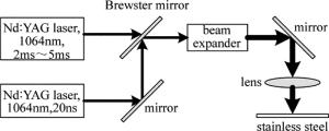
复合激光脉冲打孔实验装置如图 1所示。两束激光波长均为1064nm,毫秒激光脉宽2ms~5ms可调,频率为30Hz,单脉冲能量为2J~5J,聚焦光斑为300μm,纳秒激光脉宽为20ns,频率为10kHz,单脉冲能量为1.5mJ,聚焦光斑为100μm。两束激光通过布儒斯特片非相干合束,经过扩束准直,聚焦于厚度为5mm的SUS 304不锈钢表面。
-
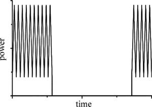
纳秒脉冲的输出由毫秒激光的脉冲有效信号控制,用以实现两束激光脉冲的同步,当毫秒脉冲宽度激光脉冲输出时纳秒脉冲激光启动输出,当毫秒激光停止输出时停止纳秒脉冲激光的输出,两束激光脉冲启动时间的延迟为微秒量级。改变毫秒激光的脉冲宽度,能够控制一个毫秒脉冲宽度内复合的纳秒脉冲个数。两束激光峰值功率叠加如图 2所示。
固定毫秒激光器的脉宽,改变平均功率,即改变毫秒激光的单脉冲能量,记录从激光作用到不锈钢背面观察到稳定的熔融溅射的时间,即为穿孔时间。改变脉宽,重复以上实验,得到不同脉宽下,毫秒激光单脉冲能量与穿孔时间的关系。
再固定毫秒激光器的脉宽,改变平均功率,即改变毫秒激光的单脉冲能量,同时叠加纳秒激光脉冲,纳秒激光的峰值功率固定在75kW,记录穿孔时间。改变毫秒激光的脉宽,重复以上实验,得到不同毫秒脉宽下,毫秒激光单脉冲能量与穿孔时间的关系。
-
将复合脉冲激光打孔后的SUS 304不锈钢厚板沿孔的轴向切割,在显微镜下观察孔的剖面形态,如图 3所示。由于不锈钢板较厚而显微镜的视场较小,5mm长的孔径形貌需分3段拍摄,从左至右分别为孔的上、中、下3段。从图中可以看到,小孔的入口圆度较好,出口孔径略小于入口,孔壁略粗糙且发黑,有重铸层。
复合脉冲叠加打孔和毫秒脉冲单独打孔的穿孔时间结果如图 4所示。由图可知,随着毫秒脉冲能量的提高,峰值功率密度增加,穿孔时间减小。在相同的毫秒脉冲能量下,纳秒脉冲的叠加大幅减小了不锈钢的穿孔时间,以脉宽为2ms的毫秒激光打孔为例,当毫秒脉冲能量为2.9J时,单光束打孔时间为105s,复合脉冲打孔时间为45s,打孔速率提高了2.3倍左右。
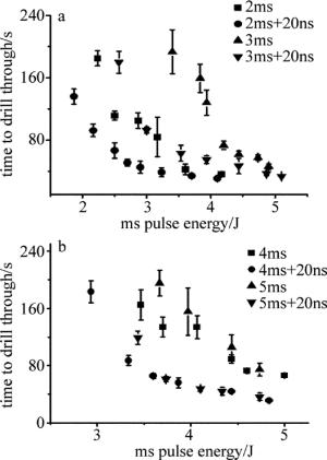
Figure 4. Time to drill through 304 stainless steel vs. ms pulse energy by ms laser drilling and by ms laser drilling superposed by ns laser
比较不同毫秒脉宽下的打孔时间可知,当毫秒脉冲能量一定时,脉宽越长,打孔时间也越长。当毫秒脉冲的能量增加到一定值后,打孔时间不再减小,打孔速率不再提高,再增加毫秒脉冲的能量没有意义,毫秒脉冲能量存在一个最佳值。
对比相同打孔时间下的2ms脉冲能量可知,复合脉冲打孔下,毫秒脉冲在单脉冲能量为2.9J时,打孔时间为45s,同样的打孔时间,毫秒激光单独打孔需要3.6J,则打孔所需的毫秒脉冲能量减少了20%左右。
-
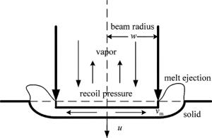
为了解释复合脉冲激光打孔中,长脉冲与短脉冲的不同作用,以及打孔速率高于长脉冲单独打孔的原因,建立图 5所示的打孔模型。一束半径为w的激光入射到材料表面,当激光功率密度足够高时,材料发生熔化以及汽化,产生的蒸发反冲压强作用于熔融液体表面,熔融物质以径向速率vm离开激光作用区域而溅射逸出,熔融层以速率u向下推进,直至材料下表面,完成穿孔(u即为打孔速率)[9-10]。
-
假设作用的激光光斑为均匀分布,材料尺寸远大于光斑尺寸,此时,激光束可以当作圆形面热源对半无穷大物体加热。同时,假设熔融物的排出仅发生于激光光斑作用区域内,熔融层的表面近似平坦且厚度相同[11]。
根据热传导方程,激光光斑中心处引起的温升为[12]:
$ \Delta T\left( {0, 0, \tau } \right) = \frac{{\arctan \left( {\sqrt {\frac{{8\alpha \tau }}{{{w^2}}}} } \right){I_{\max }}\gamma w}}{{\sqrt {2{\rm{ \mathsf{ π} }}} \kappa }} $
(1) 式中, Imax为激光峰值功率密度,材料吸收因子γ=1-R,R为材料的反射率且假设为常数,α是材料的热扩散率,τ为脉冲宽度,w为光斑半径,κ是材料的热导率。则材料的表面温度为:
$ {T_{\rm{s}}} = {T_0} + \Delta T\left( {0, 0, \tau } \right) $
(2) 式中,T0为环境温度。
饱和蒸汽压强ps与表面温度Ts相关,由BATANOV的近似方程给出[13]:
$ {p_{\rm{s}}}\left( {{T_{\rm{s}}}} \right) = {p_0}\exp \left[ {\frac{{{\lambda _{\rm{e}}}}}{{k{T_{\rm{e}}}}}\left( {1 - \frac{{{T_{\rm{v}}}}}{{{T_{\rm{s}}}}}} \right)} \right] $
(3) 式中,p0为标准大气压强,λe是单个原子蒸发所吸收的热量,k是玻尔兹曼常数,Tv为沸点。
蒸发反冲压强pr与饱和蒸汽压强ps的关系由ANISIMOV给出[14]:
$ {p_{\rm{r}}} = 0.55{p_{\rm{s}}} $
(4) 蒸发反冲压强作用在熔融层,使液体沿径向移动离开作用区域,溅射排出,排出速率为vm,ALLMEN[15]给出了其表达式:
$ {v_{\rm{m}}} = \sqrt {\frac{{2{p_{\rm{r}}}}}{\rho }} $
(5) 式中,ρ为材料密度。
ALLMEN还给出了液体排出率jl的定义,即单位时间、单位面积的液体排出质量(g·cm-2·s-1),并且给出了表达式[15]:
$ {j_1} = {\left[ {\frac{{2\alpha }}{w}\ln \left( {\frac{{{T_{\rm{s}}}}}{{{T_{\rm{m}}}}}} \right)} \right]^{\frac{1}{2}}}{p_{\rm{s}}}^{\frac{1}{4}}{\rho ^{\frac{3}{4}}} $
(6) 式中,Tm为材料的熔点。
在以蒸发反冲压强使液体溅射为主的排出机制下,材料通过蒸发形式损失的质量可被忽略[9],则打孔速率u可被表示为[15]:
$ u = \frac{{{j_1}}}{\rho } $
(7) -
根据以上公式,结合实验参量进行仿真模拟,可得到激光脉冲能量和脉冲宽度与打孔速率之间的关系,表 1中给出SUS 304不锈钢的物理特性参量[9, 16]。
Table 1. Physical parameters of 304 stainless steel
material density ρ/
(kg·m-3)melting point Tm/
Kboiling point
Tv/Kthermal conductivity
κ/(W·m-1·K-1)thermal diffusivity
α/(m2·s-1)latent heat of vaporization Lv/(J·K-1) 304 stainless steel 7900 1700 3273 30.4 4.9×10⁻⁶ 6.1×10⁶ 由(1)式得到不同脉宽下毫秒激光单脉冲能量与不锈钢材料表面温升的关系曲线,如图 6所示。根据计算可知,使不锈钢表面达到熔点所需的激光能量约为其达到沸点的一半。以脉宽为5ms的长脉冲为例,使不锈钢表面达到熔点的单脉冲能量为0.82J,达到沸点的单脉冲能量为1.58J。当脉冲能量相同时,脉宽越窄,峰值功率密度越大,材料的表面温升越高。纳秒脉冲的峰值功率密度远大于毫秒脉冲,叠加后使材料表面温度进一步升高。
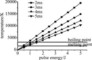
Figure 6. Relationship between temperature rising of stainless steel surface vs. ms laser pulse energy for different pulse widths
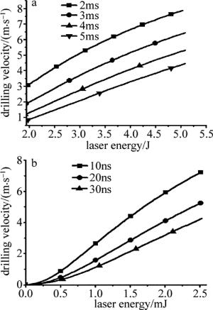
在单独采用长脉冲打孔,考虑蒸发反冲压强溅射熔融物质为主的模型中,长脉冲激光能量加热材料形成熔池,同时产生蒸发反冲压强排出液体,脉宽5ms的激光单脉冲能量需大于1.58J,根据(1)式~(7)式,得到不同脉宽作用下,打孔速率与脉冲能量的关系,如图 7a所示。
由图可知,长脉冲激光单独作用时,脉冲能量越大,打孔速率越快,相同的脉冲能量下,脉宽越窄,峰值功率密度越高,产生的蒸发反冲压强越大,溅射更加剧烈,打孔速率越快,与图 4中的实验结果一致。
在长脉冲与短脉冲复合打孔,考虑到蒸发反冲压强溅射熔融物质为主的模型中,长脉冲能量主要用于加热材料使其熔化,产生足够的熔融液体,脉宽5ms的激光单脉冲能量在0.82J~1.58J之间,短脉冲作用于熔池,产生蒸发反冲压强排出液体,根据(1)式~(7)式,得到不同纳秒脉宽作用下,打孔速率与脉冲能量的关系,如图 7b所示。
由图 7可知,复合脉冲叠加时,纳秒激光的脉冲能量越大,脉宽越窄,打孔速率越快。在相同的打孔速率下,与长脉冲激光单独作用相比,复合脉冲打孔叠加的短脉冲激光能量远小于长脉冲激光能量,且所需的长脉冲激光能量较低,则总能量降低。即复合脉冲打孔能以较小的激光能量,达到相同的打孔速率。
实验中,固定纳秒激光脉冲能量为1.5mJ,打孔时间随毫秒脉冲能量增加而减小,相同的毫秒脉冲能量下,复合脉冲打孔时间小于毫秒脉冲单独打孔,叠加的纳秒脉冲作用于熔融层表面,产生附加的蒸发反冲压强,加速了熔融液体的排出。随着毫秒激光的单脉冲能量增加,产生的溅射速率也在增加,纳秒脉冲产生的附加去除的熔融物在总的去除金属总量的比例下降,则复合脉冲叠加与单独毫秒作用的打孔时间逐渐接近,此时叠加脉冲打孔减小能量消耗的优势不再。所以,对一定能量的纳秒脉冲,毫秒脉冲能量存在最佳值,以这个参量进行打孔,复合脉冲打孔速率增长最多,纳秒脉冲的叠加优势最明显。
对脉冲宽度2ms的毫秒脉冲来说,当毫秒脉冲的单脉冲能量为3.5J左右时,毫秒脉冲单独打孔和复合脉冲激光打孔的打孔速率接近相同,此时叠加纳秒脉冲串已无必要。脉冲宽度2ms的毫秒脉冲,在单脉冲能量为2.5J~3.5J时,复合脉冲的打孔速率和打孔效率与毫秒脉冲单独打孔相比有最大差值,即在此参量下,复合脉冲激光打孔的长脉冲与短脉冲参量是最佳匹配。
-
对纳秒短脉冲与毫秒长脉冲空间合束的复合脉冲激光打孔方式进行了实验研究,建立了复合脉冲打孔的理论模型进行仿真模拟。
(1) 与毫秒脉冲单独激光打孔相比,在相同的毫秒脉冲能量下,复合脉冲激光打孔能大幅减小打孔时间、提高打孔速率,打孔速率可提高2.3倍左右。
(2) 复合脉冲激光打孔中,脉冲能量越大,脉冲宽度越窄,则峰值功率密度越大,激光打孔速率越快。
(3) 复合脉冲激光打孔中,毫秒脉冲与纳秒脉冲的能量存在最佳匹配,对单脉冲能量为1.5mJ、脉冲宽度为20ns的纳秒脉冲,脉冲宽度为2ms的毫秒脉冲的最佳单脉冲能量为2.5J~3.5J。这为复合脉冲打孔中,长脉冲与短脉冲激光的参量选择提供了依据。
复合脉冲深度激光打孔的实验研究
Experimental study on deep laser drilling by the superposed pulsed lasers
-
摘要: 为了进一步提高激光在金属厚板上深度打孔的速率,针对5mm厚不锈钢板,采用高峰值功率短脉冲串叠加大能量长脉冲的双光束复合激光打孔方法,建立了复合脉冲激光打孔的理论模型,提出大能量长脉冲激光束的主要作用是熔化金属,排出金属熔融物主要靠高峰值功率密度的激光脉冲串,并研究了脉冲能量、脉冲宽度、打孔方式等不同激光参量下的激光打孔效果。结果表明,与长脉冲激光单独激光打孔相比,复合脉冲激光打孔能大幅减小穿孔时间,对脉宽2ms、单脉冲能量2.9J的长脉冲,复合脉冲打孔速率提高2.3倍,所需能量减少20%,且脉冲能量越大,脉冲宽度越窄,打孔速率越快。此研究为复合脉冲打孔的激光器选择提供了依据。Abstract: To further improve the velocity of deep laser drilling in thick metal plate, aiming at 5mm thick stainless steel plate, laser drilling method of long pulse laser with high pulse energy superposed by short pulse laser with high peak power was put forward. The theoretical model of laser drilling by superposed pulsed lasers was established. The function of long pulse laser with high pulse energy was to melt metals, while the removal of metal melted things relied mainly on short pulse laser of high peak power. The drilling effects under different laser parameters (pulse energy, pulse width and drilling method) were studied. The results show that, compared with laser drilling by single long pulse, laser drilling by the superposed pulse can substantially reduce the drilling time. For long pulse of 2ms pulse width and 2.9J pulse energy, the drilling velocity of superposed pulsed lasers increases by 2.3 times while the energy cost reduces 20%. And the larger the pulse energy is, the narrower the pulse width is, the faster the drilling velocity becomes. The study provides a basis for laser selection in laser drilling by the superposed pulsed lasers.
-
Key words:
- laser technique /
- laser drilling /
- superposed pulse /
- pulse energy /
- pulse width
-
Table 1. Physical parameters of 304 stainless steel
material density ρ/
(kg·m-3)melting point Tm/
Kboiling point
Tv/Kthermal conductivity
κ/(W·m-1·K-1)thermal diffusivity
α/(m2·s-1)latent heat of vaporization Lv/(J·K-1) 304 stainless steel 7900 1700 3273 30.4 4.9×10⁻⁶ 6.1×10⁶ -
[1] XIN F L.Study on high quality laser drilling technology.Beijing: Beijing University of Technology, 2006: 5-8(in Chinese). [2] WANG J Y. Advanced laser processing technology. Beijing: China Machine Press, 1995:3-8(in Chinese). [3] WANG X D, MICHALOWSKI A, DAUSINGER F, et al. Double-pulse technique for short pulse laser drilling. Laser Technology, 2009, 33(3):283-286(in Chinese). [4] BREITLING D, DAUSINGER F. Precision drilling of metals and ceramics with short- and ultrashort-pulsed solid state lasers. Proceedings of the SPIE, 2002, 4426:104-107. doi: 10.1117/12.456897 [5] ZHANG Y, CHEN Y Q, ZHU G Zh, et al. Research on the superposed pulsed Nd:YAG laser with single beam. Laser Technology, 2016, 40(3): 311-314(in Chinese). [6] FOX J A. A method for improving continuous wave laser penetration of metal targets. Applied Physics Letters, 1975, 26(12):682-684. doi: 10.1063/1.88024 [7] LEHANE C, KWOK H S. Enhanced drilling using a dual-pulse Nd:YAG laser. Applied Physics, 2001, A73(1):45-48. [8] BRAJDIC M, WALTHER K, EPPELT U. Analysis of laser drilled deep holes in stainless steel by superposed pulsed Nd:YAG laser radiation. Optics & Lasers in Engineering, 2008, 46(9):648-655. [9] SEMAK V, MATSUNAWA A. The role of recoil pressure in energy balance during laser materials processing. Journal of Physics, 1998, D30(18):2541-2552. [10] SEMAK V V, KNOROVSKY G A, MAcCALLUM D O, et al. Effect of surface tension on melt pool dynamics during laser pulse interaction. Journal of Physics, 2006, D39(3):590-595. [11] ZHENG Q G, ZHUANG Q R, ZHANG W Zh. The interaction between laser and material. Wuhan: Huazhong University of Science Press, 1996:29-32(in Chinese). [12] HENDOW S T, SHAKIR S A. Structuring materials with nanosecond laser pulses. Optics Express, 2010, 18(10):10188-99. doi: 10.1364/OE.18.010188 [13] BATANOV V A, RADKEVICH A O, TELYATNIKOV A L, et al. Parametric processes in optically pumped FIR lasers. International Journal of Infrared & Millimeter Waves, 1988, 9(9):761-779. [14] ANISIMOV S I, KHOKHLOV V A. Instabilities in laser-matter interaction. Boca Raton, Florida, USA: Chemical Rubber Company Press, 1995:18-23. [15] ALLMEN M, BLATTER A. Laser-beam interactions with materials: physical principles and applications. New York, USA: Springer Science & Business Media, 1995:38-39. [16] XIE J, KAR A. Mathematical modeling of melting during laser materials processing. Journal of Applied Physics, 1997, 81(7):3015-3022. doi: 10.1063/1.364336 -


 网站地图
网站地图

 下载:
下载:
