-
矢量光束是偏振态在空间呈非均匀分布的光束。矢量光束在高数值孔径下的紧聚焦特性吸引了很多人的研究[1-6],例如:径向偏振光在紧聚焦的情况下会在沿轴方向产生纵向分量;而角向偏振光在紧聚焦的情况下会在焦平面产生中空的光场分布。由于矢量光束聚焦场的这些新颖特性,使其在粒子加速[7-8]与捕获[9-10]、扫描光学显微镜[11-12]、激光切割与加工[13-14]等领域应用广泛。
当光场相位围绕着中心点螺旋增加或减小时,称这种相位分布为涡旋相位。LI等人[15]利用矢量衍射理论研究了涡旋相位的聚焦特性。研究表明,通过调整拓扑荷m[16]以及聚焦系统,能够在聚焦场实现从单个焦点到两个重叠焦点的改变。这些特性适用于诸如光学捕获[17-18]和粒子加速[19]方面的相关应用。而最近的研究表明,当在矢量光束上加载涡旋相位后,聚焦场的强度分布将发生变化,展现出更加与众不同的特性。例如通过在角向偏振光场加载涡旋相位,HAO等人[20]得到了比同等条件下的径向偏振光更小的焦点。
于是作者对径向矢量高斯光束加载涡旋相位的聚焦特性进行研究。基于矢量衍射理论,推导了径向矢量高斯光束编码单个涡旋的聚焦场表达式,并研究了聚焦场分布随拓扑荷变化的规律。在此基础上,进一步推导了径向矢量高斯光束编码对称的两个涡旋相位的聚焦场表达式,并给出了数值模拟结果。研究结果所展示的聚焦场特性对于矢量光束的调控具有重要的理论意义和实际价值。
-
矢量光束在高数值孔径物镜下的聚焦场由RICHARDS和WOLF提出的矢量Debye积分理论[21]所描述。根据这个理论,对于径向偏振光,焦点附近的电场分布可以表示为:
$ \mathit{\boldsymbol{E}}\left( {\rho ,\varphi ,z} \right) = \frac{{{\rm{i}}\mathit{f}}}{\lambda }\int \begin{array}{l} 2{\rm{ \mathsf{ π} }}\\ 0 \end{array} \int \begin{array}{l} \alpha \\ 0 \end{array} A\left( {\theta ,\phi } \right)k\left( {\rho ,\varphi ,z,\theta ,\phi } \right){\rm{d}}\theta {\rm{d}}\phi $
(1) $ \begin{array}{l} k\left( {\rho ,\varphi ,z,\theta ,\phi } \right) = \left\{ {\left[ {\cos \theta \cos \left( {\phi - \varphi } \right)} \right]} \right.{\mathit{\boldsymbol{\widehat e}}_\rho } + \\ \;\;\;\;\;\;\left. {\left[ {\cos \theta \sin \left( {\phi - \varphi } \right)} \right]{{\mathit{\boldsymbol{\widehat e}}}_\varphi } + \sin \theta {{\mathit{\boldsymbol{\widehat e}}}_z}} \right\} \times \\ \;\;\;\;\;\;\exp \left\{ { - {\rm{i}}\mathit{k}\left[ {z\cos \theta + \rho \sin } \right.} \right.\theta \cos \left( {\varphi - } \right.\\ \;\;\;\;\;\;\;\;\;\;\;\;\;\;\;\left. {\left. {\left. \phi \right)} \right]} \right\}\sin \theta \sqrt {\cos \theta } {\rm{d}}\phi \end{array} $
(2) 式中,θ是物镜对焦点的最大孔径角, 也即物镜数值孔径; ϕ是极坐标下的角度; A(θ, ϕ)是出瞳切趾函数; λ是入射光波长; k是波数; α=arcsinθ是最大收敛角,由θ所决定; p, φ和z表示焦点处的柱矢量坐标; ${\mathit{\boldsymbol{\widehat e}}_\rho } $, ${{{\mathit{\boldsymbol{\widehat e}}}_\varphi }} $和${{{\mathit{\boldsymbol{\widehat e}}}_z}} $是柱坐标中的单位向量。二重积分的上下限一个为0~2π,它表示沿着角向积分一周;另一个为0~最大收敛角α,它表示沿着径向的积分。这两个积分范围共同确定对焦场有贡献的入射场的范围。
-
当径向矢量高斯光束编码单个涡旋相位时,其电场可以表示为:
$ E\left( {r,\phi } \right) = \exp \left( {\frac{{ - {r^2}}}{{{w^2}}}} \right)\exp \left( {{\rm{i}}\mathit{m}\phi } \right) $
(3) 式中,r表示极坐标下角向距离, m表示涡旋相位的拓扑荷, w为光束尺寸的常数。
由于物镜的设计通常满足正弦条件,于是有r=fsinθ[22], f是高数值孔径物镜的焦距。将(3)式代入(1)式并化简,得到聚焦场${\mathit{\boldsymbol{\widehat e}}_\rho } $, ${{{\mathit{\boldsymbol{\widehat e}}}_\varphi }} $和${{{\mathit{\boldsymbol{\widehat e}}}_z}} $的电场分量为:
$ \begin{array}{l} {\mathit{\boldsymbol{E}}_\rho }\left( {\rho ,\varphi ,z} \right) = \frac{{ - {\rm{i}}\mathit{kf}}}{{2{\rm{ \mathsf{ π} }}}}\int \begin{array}{l} \alpha \\ 0 \end{array} P\left( \theta \right)\left\{ {{\rm{ \mathsf{ π} cos}}\theta {\rm{exp}}\left( {{\rm{i}}\mathit{m}\varphi } \right)} \right.{{\rm{i}}^{ - \left( {m + 1} \right)}} \times \\ \;\;\;\;{{\rm{J}}_{\mathit{m}{\rm{ + 1}}}}\left( {k\rho \sin \theta } \right) + {\rm{ \mathsf{ π} cos}}\theta \exp \left( {{\rm{i}}\mathit{m}\varphi } \right){{\rm{i}}^{ - \left( {m - 1} \right)}} \times \\ \;\;\;\;\;\;\;\;\;\;\;\;\;\;\;\;\;\;\;\left. {{{\rm{J}}_{\mathit{m} - 1}}\left( {k\rho \sin \theta } \right)} \right\}{\rm{d}}\theta \end{array} $
(4) $ \begin{array}{l} {\mathit{\boldsymbol{E}}_\varphi }\left( {\rho ,\varphi ,z} \right) = \frac{{ - {\rm{i}}\mathit{kf}}}{{2{\rm{ \mathsf{ π} }}}}\int \begin{array}{l} \alpha \\ 0 \end{array} P\left( \theta \right)\left\{ {{\rm{ \mathsf{ π} cos}}\theta {\rm{exp}}\left( {{\rm{i}}\mathit{m}\varphi } \right)} \right.{{\rm{i}}^{ - \left( {m + 1} \right)}} \times \\ \;\;\;\;{{\rm{J}}_{\mathit{m}{\rm{ + 1}}}}\left( {k\rho \sin \theta } \right) - {\rm{ \mathsf{ π} cos}}\theta \exp \left( {{\rm{i}}\mathit{m}\varphi } \right){{\rm{i}}^{ - \left( {m - 1} \right)}} \times \\ \;\;\;\;\;\;\;\;\;\;\;\;\;\;\;\;\;\;\;\left. {{{\rm{J}}_{\mathit{m} - 1}}\left( {k\rho \sin \theta } \right)} \right\}{\rm{d}}\theta \end{array} $
(5) $ \begin{array}{l} {\mathit{\boldsymbol{E}}_z}\left( {\rho ,\varphi ,z} \right) = \frac{{ - {\rm{i}}\mathit{kf}}}{{2{\rm{ \mathsf{ π} }}}}\int \begin{array}{l} \alpha \\ 0 \end{array} P\left( \theta \right)\left\{ {{\rm{2 \mathsf{ π} exp}}\left( {{\rm{i}}\mathit{m}\varphi } \right)} \right.{{\rm{i}}^{ - m}} \times \\ \;\;\;\;\;\;\;\;\;\;\;\;\;\;\;\;\;\;\;\left. {{{\rm{J}}_\mathit{m}}\left( {k\rho \sin \theta } \right)\sin \theta } \right\}{\rm{d}}\theta \end{array} $
(6) 式中,$P\left( \theta \right) = \left\{ {\exp \left[ { - \left( {{\rm{i}}\mathit{k}z\cos \theta + {f^2}{{\left( {\sin \theta } \right)}^2}/{w^2}} \right)} \right]} \right\} \times \sqrt {\cos \theta } \sin \theta , $ Jm(x)是m阶第1类贝塞尔函数。该一重积分的范围就是径向需要积分的范围,即从0~α。此一重积分表示入射场的一个环状区域对聚焦场的贡献。
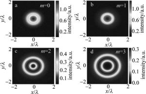
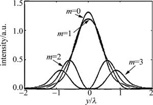
根据(4)式~(6)式, 取参量λ=632.8nm, w=2mm, θ=0.9,模拟计算了矢量光束编码单个涡旋相位的聚焦场。图 1中给出当拓扑荷m取0, 1, 2和3时所对应的聚焦场强度分布, 它展示了拓扑荷m对于焦场光斑图样的影响。由于入射光是径向偏振光,因此当拓扑荷m=0时,焦场只有一个焦点,如图 1a所示。随着拓扑荷数增加,在聚焦场的中心出现光学暗点,即2维中空聚焦场,并且中空聚焦场的半径也逐渐增大,如图 1c和图 1d所示。为了便于对比分析,将焦平面上x=0、沿y方向的强度分布显示图 2中。它更加直观地显示了聚焦场能量分布随拓扑荷m变化的数量关系。图 2说明,随着拓扑荷m的增加,聚焦场中心的光强逐渐变弱;当m=2和m=3时,能够产生2维中空聚焦场,并且中空场的半径也随着m的增加而增加。与角向矢量光的紧聚焦场相比,径向矢量光束编码单个涡旋时的紧聚焦场同时具有径向分量和纵向分量,这进一步提升了光学微操控[23-24]的灵活性。
-
在径向矢量光束上编码两个对称的涡旋相位,并且两个涡旋相位的拓扑荷m相同。令拓扑荷m均为1的两个涡旋相位分别位于入射平面x=a和x=-a处。这样,入射光场的电场表达为:
$ \mathit{E}\left( {r,\phi } \right) = \exp \left( {\frac{{ - {r^2}}}{{{w^2}}}} \right)\left( {r{e^{{\rm{i}}\phi }} - a} \right)\left( {r{e^{{\rm{i}}\phi }} + a} \right) $
(7) 两个涡旋相位之间的距离由a确定。当a=0时,两个涡旋相重叠,这与编码单涡旋相位拓扑荷m=2的情况相同。随着a逐渐增大,两个涡旋相位逐渐分离,聚焦场的分布也随着a的改变而出现新的变化。
将(7)式代入(1)式中并化简,聚焦场${\mathit{\boldsymbol{\widehat e}}_\rho } $, ${{{\mathit{\boldsymbol{\widehat e}}}_\varphi }} $和${{{\mathit{\boldsymbol{\widehat e}}}_z}} $的电场分量分别表示为:
$ \begin{array}{l} {\mathit{\boldsymbol{E}}_\rho }\left( {\rho ,\varphi ,z} \right) = \frac{{ - {\rm{i}}\mathit{kf}}}{{2{\rm{ \mathsf{ π} }}}}\int \begin{array}{l} \alpha \\ 0 \end{array} P\left( \theta \right)\left\{ {{\rm{i \mathsf{ π} cos}}\theta } \right.\left[ {{f^2}{{\left( {\sin \theta } \right)}^2}{{\rm{e}}^{{\rm{i2}}\varphi }}} \right. \times \\ \left. {\left. {\left( {{{\rm{J}}_{\rm{3}}}\left( {k\rho \sin \theta } \right) - {{\rm{J}}_{\rm{1}}}\left( {k\rho \sin \theta } \right)} \right) + 2{a^2}{{\rm{J}}_{\rm{1}}}\left( {k\rho \sin \theta } \right)} \right]} \right\}{\rm{d}}\theta \end{array} $
(8) $ \begin{array}{l} {\mathit{\boldsymbol{E}}_\varphi }\left( {\rho ,\varphi ,z} \right) = \frac{{ - {\rm{i}}\mathit{kf}}}{{2{\rm{ \mathsf{ π} }}}}\int \begin{array}{l} \alpha \\ 0 \end{array} P\left( \theta \right)\left\{ {{\rm{ \mathsf{ π} cos}}\theta } \right.\left[ {{f^2}{{\left( {\sin \theta } \right)}^2}{{\rm{e}}^{{\rm{i2}}\varphi }}} \right. \times \\ \;\;\;\;\;\;\;\;\;\;\left. {\left. {\left( {{{\rm{J}}_{\rm{3}}}\left( {k\rho \sin \theta } \right){\rm{ + }}{{\rm{J}}_{\rm{1}}}\left( {k\rho \sin \theta } \right)} \right)} \right]} \right\}{\rm{d}}\theta \end{array} $
(9) $ \begin{array}{l} {\mathit{\boldsymbol{E}}_z}\left( {\rho ,\varphi ,z} \right) = \frac{{ - {\rm{i}}\mathit{kf}}}{{2{\rm{ \mathsf{ π} }}}}\int \begin{array}{l} \alpha \\ 0 \end{array} P\left( \theta \right)\left\{ { - {\rm{2 \mathsf{ π} sin}}\theta } \right. \times \\ \left. {\left[ {{f^2}{{\left( {\sin \theta } \right)}^2}{{\rm{e}}^{{\rm{i2}}\varphi }}{{\rm{J}}_{\rm{2}}}\left( {k\rho \sin \theta } \right) + {a^2}{{\rm{J}}_{\rm{0}}}\left( {k\rho \sin \theta } \right)} \right]} \right\}{\rm{d}}\theta \end{array} $
(10) 式中, J0(x), J1(x), J2(x)和J3(x)分别为0阶、1阶、2阶以及3阶第1类贝塞尔函数。
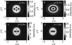
根据(8)式~(10)式的推导结果,取参量λ=632.8nm, θ=0.9, 计算在两个涡旋之间的间距,即不同a值情况下焦场的强度分布,结果如图 3所示。图 3a为a=0w的情况,这等效于拓扑荷m为2的径向矢量光束编码单涡旋相位的聚焦场,它产生了一个2维中空场。随着两个涡旋相位之间距离的增加,聚焦场中开始出现两个沿y方向对称分布的光学暗点,如图 3b所示。随着涡旋之间距离的继续增加,这两个光学暗点之间的距离也随着增加,但其能量轮廓则不断下降,如图 3c所示。当a增加到1.0w时,两个光学暗点几乎消失,焦平面出现了一个亮的条形光班。总之,当两个涡旋重叠时,只有一个光学暗点出现;当两个涡旋相位逐渐分离开时,光学暗点开始分成两个并且随着涡旋相位之间距离的持续增加而消失。此外,对于特定的a值,两个光学暗点的能量分布和形状具有相同的特征。
-
研究并给出了聚焦场的特性与涡旋相位的拓扑荷和间距之间的关系。发现,当编码单个涡旋相位并且拓扑荷为2和3时,聚焦场中存在一个2维中空能量分布,这种聚焦场适用于对单个粒子的微操纵,并且这种2维中空场能量分布的半径与拓扑荷m的大小相关,即通过调节拓扑荷的大小可调控中空场的大小,这增加了操控微粒大小的自由度。而当编码两个涡旋相位(拓扑荷m=1)时,聚焦场的分布依赖于两个涡旋相位之间的间距。当两个涡旋相位同时位于入射光束的中心时,聚焦场只会产生一个光学暗点,而随着两个涡旋相位中心的逐渐远离,此前的一个光学暗点逐渐分裂成两个暗点,这意味着这种聚焦场可以同时操控两个折射率不同于周围煤质的粒子。同时也发现,两个暗点的间距与涡旋相位的间距有关,因此可以通过调节涡旋相位间距来调整暗点的间距,从而增加对不同间距的双微粒的操控的自由度。
涡旋相位编码的径向矢量光束的紧聚焦特性
Compact focusing properties of radial vector beam with vortex phase encoding
-
摘要: 为了研究涡旋相位编码的径向矢量高斯光束经过高数值孔径物镜之后的聚焦特性,采用RICHARDS和WOLF提出的矢量积分理论和数值模拟方法,对聚焦场的特征进行了理论分析和模拟实验验证,取得聚焦场分布随涡旋相位物理参量之间的数据关系。结果表明,当单个涡旋相位编码于径向矢量高斯光束时,在聚焦场能够获得2维的径向和纵向分量;当双涡旋相位对称地编码于径向高斯矢量光束时,聚焦场会出现两个光学暗点,此光学暗点处的折射率低于周围环境的折射率。这一结果对提高光学微操控的灵活性,以及对双微粒的捕获与操控是有帮助的。Abstract: In order to study the focusing properties of radial vector Gaussian beam with vortex phase encoding through objective mirror with high numerical aperture, the vector integral theory and numerical simulation method proposed by RICHARDS and WOLF were adopted. After theoretical analysis and simulation verification of the characteristics of focused field, the relationship between focused field distribution and vortex phase physical parameters was gotten. The results show that, when radial vector Gaussian beam is encoded by single vortex, 2-D radial and longitudinal components of focused field can be obtained. When radial vector Gaussian beam is encoded by double vortex phase symmetrically, two optical dark cores are formed in focal plane. The refractive indexs of two optical dark cores are lower than the indexs of the surrounding environment. The study is helpful to improve the flexibility of optical micro-manipulation and capture and control the double minute.
-
[1] HAO X, KUANG C, WANG T, et al. Phase encoding for sharper focus of the azimuthally polarized beam[J].Optics Letters, 2010, 35(23):3928-3930. doi: 10.1364/OL.35.003928 [2] CHEN W, ZHAN Q. Three-dimensional focus shaping with cylindrical vector beams[J].Optics Communications, 2006, 265(2):411-417. doi: 10.1016/j.optcom.2006.04.066 [3] DORN R, QUABIS S, LEUCHS G. Sharper focus for a radially polarized light beam[J].Physical Review Letters, 2003, 91(23):233901. doi: 10.1103/PhysRevLett.91.233901 [4] WEI T D, ZHANG Y H, TANG Y G. Influence of polarization state, phase and amplitude on the loss of focal spot in stimulated radiation[J].Optics and Precision Engineering, 2014, 22(5):1157-1164(in Chinese). doi: 10.3788/OPE. [5] LU Y Q, HU S L, LU Y, et al. Plasmonic lens with long focal length and tight focusing under illumination of a radially polarized light[J].Acta Physica Sinica, 2015, 40(9):476-482(in Chinese). [6] LIU Z Y, LI L, HU B T. Focusing property for ultra-short pulse laser reflected by off-axis parabolic mirrors[J]. Laser Technology, 2012, 36(5):657-661(in Chinese). [7] KIMURA W D, KIM G H, ROMEA R D, et al. Laser acceleration of relativistic electrons using the inverse Cherenkov effect[J].Physical Review Letters, 1995, 74(4):546-549. doi: 10.1103/PhysRevLett.74.546 [8] DAI L, LI J X, ZANG W P, et al. Vacuum electron acceleration driven by a tightly focused radially polarized Gaussian beam[J].Optics Express, 2011, 19(10):9303-9308. doi: 10.1364/OE.19.009303 [9] KUGA T, TORII Y, SHIOKAWA N, et al. Novel optical trap of atoms with a doughnut beam[J]. Physical Review Letters, 1997, 78(25):4713-4216. doi: 10.1103/PhysRevLett.78.4713 [10] GUO L N, TANG Zh L, WANG J. Trapping Rayleigh particles with double-ring radially polarized vortex beams[J].Acta Laser Biology Sinica, 2015, 24(2):145-151(in Chinese). [11] YOUNGWORTH K S, BROWN T G. Inhomogeneous polarization in scanning optical microscopy[J]. Proceeding of the SPIE, 2000, 3919:75-85. doi: 10.1117/12.384181 [12] ZHAO Y Q, SHEN Zh M, WANG P. Discussion on optical microscope imaging modes and composion of cold light source device using frequency splitting[J]. Rock and Mineral Analysis, 2014, 33(5):674-680(in Chinese). [13] NIZIEV V G, NESTEROV A V. Influence of beam polarization on laser cutting efficiency[J]. Journal of Physics, 1999, D32(13):1455-1461. [14] RAHMAN R R A, SUN S, WANG G, et al. An investigation of cutting forces and cutting temperatures during laser-assisted machining of the Ti-6Cr-5Mo-5V-4Al beta titanium alloy[J].International Journal of Machine Tools & Manufacture:Design, Research and Application, 2012, 63(4):58-69. [15] LI J, LU T, GUO L. Focusing properties of vector vortex-bearing beams[J]. Optics and Lasers in Engineering, 2012, 50(7):996-1000. doi: 10.1016/j.optlaseng.2012.01.015 [16] SONG X F, XU J B, ZHANG K. Research on method for determing the topological charge number and the positive or negative of Laguerre-Gaussian beam[J]. Journal of Shandong Normal University (Natural Science Edition), 2015, 30(2):73-76(in Chinese). [17] ZHAN Q. Trapping metallic Rayleigh particles with radial polarization[J]. Optics Express, 2004, 12(15):3377-3382. doi: 10.1364/OPEX.12.003377 [18] GAO Sh J, SHENG L, WU Zh Y, et al. Rapid restoration and real-time detection on spot image of atmospheric laser communication[J]. Optics and Precision Engineering, 2015, 23(8):2393-2399(in Chinese). doi: 10.3788/OPE. [19] TIDWELL S C, KIM G H, KIMURA W D. Efficient radially polarized laser beam generation with a double interferometer.Applied Optics, 1993, 32(27):5222-5229. doi: 10.1364/AO.32.005222 [20] HAO X, KUANG C, WANG T, et al. Phase encoding for sharper focus of the azimuthally polarized beam[J]. Optics Letters, 2010, 35(23):3928-3930. doi: 10.1364/OL.35.003928 [21] RICHARDS B, WOLF E. Electromagnetic diffraction in optical systems. Ⅱ. Structure of the image field in an aplanatic system[J]. Royal Society, 1959, 253(1274):358-379. [22] GU M. Advanced optical imaging theory[M].Berlin, Germany:Springer Heidelberg, 2000:237-238. [23] WANG H W, LIU X H, LI Y M, et al. Optical technic of isolation a single chromosome[J]. Acta Biophysica Sinica, 2004, 20(1):50-56(in Chinese). [24] HU J F, XU G Y, HAO Y Zh. Multi-objective optimization of micro-manipulation stage based on response surface method[J].Optics and Precision Engineering, 2015, 23(4):1096-1104(in Chinese). doi: 10.3788/OPE. -


 网站地图
网站地图


 下载:
下载:


