Study of far-field interference pattern for coherent Gaussian beams based on Mach-Zehnder interferometer
-
摘要: 为了使远场相干光斑分布及干涉图样的条纹间距和条纹对比度满足激光主动相干探测的要求,对基于马赫-曾德尔干涉原理的相干光发射装置发出的相干高斯光束在远场的扫描相干光场分布特性进行了分析,推导了高斯光束远场扫描相干光场的解析光强分布公式,得到了高斯光束远场扫描干涉图样。利用物理光学相关原理推导了远场的相干光光程差、干涉图样的条纹间距以及条纹对比度的表达式。数值仿真分析了马赫-曾德尔干涉光发射装置的分束镜旋转角度、探测距离和扫描角速度对远场相干光强分布特性的影响,得到了这几个物理量之间的定量关系。结果表明,远场扫描相干光强分布主要受到分束镜旋转角度、探测距离和发射装置扫描角速度等参量影响;干涉光发射装置的分束镜旋转角度同时影响远场接收屏上干涉图样的条纹间距及条纹对比度。该研究结果对实际探测中如何选取分束镜的旋转角、使其在满足条纹间距目标尺寸要求的前提下,适当调节旋转角度,获得尽可能大的条纹对比度是有帮助的。
-
关键词:
- 物理光学 /
- 马赫-曾德尔干涉原理 /
- 主动相干探测 /
- 扫描相干高斯光束 /
- 远场干涉图样
Abstract: In order to make the quality of fringe spacing and fringe visibility of interference pattern to meet the strict demands of active coherent laser detecting system of far distance, the distribution characteristics of coherent Gaussian beams based on Mach-Zehnder interferometer were analyzed. Optical intensity distribution of coherent Gaussian beams was deduced. Then interference pattern of scanning coherent Gaussian beams was gotten. The expressions of optical path difference, fringe spacing and fringe visibility based on Mach-Zehnder interferometer were derived by physical optics theory. The influences of rotation angle of beam splitter, detection distance and scanning speed on distribution characteristics of coherent light of far distance were analyzed and simulated numerically. As a result, the quantitative relation of rotation angle of beam splitter, detection distance and scanning speed was found. The results show that the distribution of coherent light of far distance is mainly controlled by rotation angle of beam splitter, detecting distance and scanning speed etc. Rotation angle of beam splitter in the interferometer has the influence on both fringe spacing and fringe visibility. The conclusion is helpful to choose the rotation angle in the experiment. Fringe spacing and fringe visibility should be taken into consideration simultaneously and the rotation angle of beam splitter is adjusted. It's useful to make the fringe visibility as large as possible. -
引言
由于激光主动探测技术具有抗背景干扰能力强、捕获跟踪目标更为快速精准、特别适用于远、小、暗目标的侦察探测等特点,因此被广泛应用于战场环境中武器装备的光学系统的侦察与定位。激光主动探测技术利用光电系统中光电传感器的光敏面或分划板不能对入射光全部吸收,同时将部分入射光原路反射的特性,在发射端接收原路返回的信号对目标进行探测,一般这种回波信号会比普通漫反射回波高出2~4个量级[1-3]。近些年,越来越多的研究人员致力于利用激光主动探测手段获取更多的目标特性进而达到目标识别的目的。有研究者针对猫眼目标的反射光的空间分布特征进行了研究,虽然这些特征中含有大量与背景漫反射光不同的信息,但依然无法解决光学目标因口径小而难以发现识别的问题。研究表明,这种单光束的探测方式在远场应用中能够获取的目标信息十分有限,当背景光较强时,光学目标的回波信号还会湮没在背景信号中,甚至无法有效判断威胁光学目标的存在[4-8]。因此,为了进一步得到更多的定量信息以提高激光主动探测系统的可靠性和智能性,有研究者从激光的发射体制入手,通过改变探测激光的单一发射模式,来获取更多目标信息[9-11]。ZHAO等人提出利用组合光束主动相干探测的方式对目标进行扫描识别,并对其可行性进行了初步的验证[12]。
激光主动相干探测方法系统应用中,对扫描光束的远场相干特性分析是必不可少的,通过分析结果能够有助于对远场干涉图样的调节和控制,从而为下一步的目标探测与识别提供参考。本文中针对基于马赫-曾德尔(Mach-Zehnder, M-Z)干涉原理的相干光发射装置发出的相干高斯光束在远场的扫描相干光场分布特性进行分析,研究远场扫描相干光强分布主要受分束镜旋转角度、探测距离和发射装置扫描角速度等参量的影响情况。
1. 基于马赫-曾德尔干涉原理的主动相干探测扫描激光发射机制
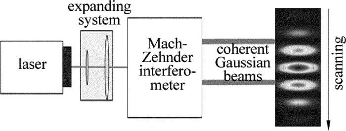
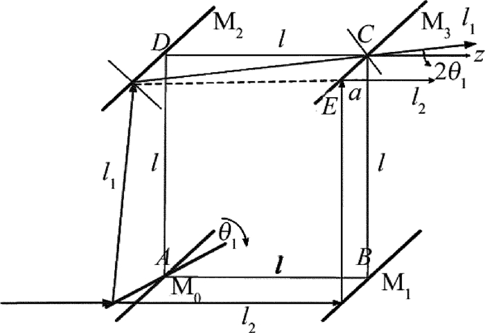
马赫-曾德尔干涉装置在工程应用中通常用来测量光学零件或光学系统的像差[13],基于马赫-曾德尔干涉原理的干涉光发射装置具有对远场相干光良好的可控性,其原理如图 1所示。通过装置中分束镜角度的微小偏转可以实现远场相干光场的微调,从而获得理想的远场干涉图样。图中M0, M1, M2和M3是与水平成45°放置的薄透镜,为获得明暗相间的干涉条纹,将分束镜M0顺时针转动θ1。一束高斯光沿z轴方向入射到改装的马赫-曾德尔干涉仪的分束镜M0,经过M0分成两束光l1和l2,继续沿z轴方向传播入射到反射镜M1,经M1反射沿垂直于z轴的y轴方向传播,最后经分束镜M3反射沿z轴方向出射;l1经M0反射,反射光偏转2θ1传播到达反射镜M2,经M2反射继续传播到达分束镜M3,经M3折射后沿与z轴夹角2θ1方向射出,由于M0旋转造成两束光相位差的存在,使得两束光在远场发生干涉。
1.1 远场扫描相干光强分布
如图 1所示,l1和l2分别在分束镜M3的C点和E点处射出,设E点到¯BC的距离为a,则由图可得tan(2θ1)=al+a,从而解出a=ltan(2θ1)1−tan(2θ1), 其中, l是透镜间距。设C点坐标为(0,a2,a2),则有E点坐标为(0,−a2,−a2)。一束基模高斯光束经分束镜M0分为从C点和E点射出的l1和l2两束光到达距离激光发射装置为L的接收屏上,当扫描时间为t时,设相干高斯光束的重心在接收屏上的坐标为(Δx, Δy),则有:
{Δx=ωxL(t−L/c)Δy=ωyL(t−L/c) (1) 式中,ωx, ωy分别为探测激光沿x轴正方向和y轴正方向的扫描角速度,c为激光在自由空间中的传播速度。
图 2为相干高斯光束远场扫描示意图。为便于后面的复杂公式推导,引入q参量来简化高斯光束光场的表达形式。假设扫描方向为沿y轴负向,则扫描时间为t时,l1和l2两束光在接收平面上的复振幅分布可以分别表示为[14-15]:
Ul1(x,y,L)=U0w0w(L)exp[−i(kL+arctanLg)]×exp[−ik(x−Δx)2+(y−a/2−Δy)22q(L)]×exp[−ikysin(2θ1)] (2) Ul2(x,y,L)=U0w0w(L)exp[−i(kL+arctanLg)]×exp[−ik(x−Δx)2+(y+a/2−Δy)22q(L)] (3) 式中,
\frac{1}{{q\left( L \right)}} = \frac{1}{{R\left( L \right)}} - {\rm{i}}\frac{\lambda }{{{\rm{ \mathsf{ π} }}{w^2}\left( L \right)}} (4) \left\{ \begin{array}{l} w\left( L \right) = {w_0}\sqrt {1 + {{\left( {\frac{L}{g}} \right)}^2}} \\ R\left( L \right) = L + \frac{{{g^2}}}{L} \end{array} \right. (5) 式中,w0为高斯光束的束腰半径,即z=0处的w值,g为高斯光束的焦参量,g=πw02/λ, 波数k=2π/λ。则两束光在距离为L处的接收屏上的相干光场的复振幅分布U为:
\begin{array}{*{20}{c}} {U = {U_{{l_1}}} + {U_{{l_2}}} = {U_0}\frac{{{w_0}}}{{w\left( L \right)}}\exp \left[ { - {\rm{i}}\left( {kL + \arctan \frac{L}{g}} \right)} \right] \times }\\ {\left\{ {\exp \left[ { - {\rm{i}}k\frac{{{{\left( {x - \Delta x} \right)}^2} + {{\left( {y - a/2 - \Delta y} \right)}^2}}}{{2q\left( L \right)}}} \right] \times } \right.}\\ {\exp \left[ { - {\rm{i}}ky\sin \left( {2{\theta _1}} \right)} \right] + }\\ {\left. {\exp \left[ { - {\rm{i}}k\frac{{{{\left( {x - \Delta x} \right)}^2} + {{\left( {y + a/2 - \Delta y} \right)}^2}}}{{2q\left( L \right)}}} \right]} \right\}} \end{array} (6) 因此,两束干涉高斯光束在接收屏上的相干光场的光强分布为:
\begin{array}{*{20}{c}} {I = {U^ * }U = U_0^2\frac{{w_0^2}}{{{w^2}\left( L \right)}} \times }\\ {\left\{ {2 + \exp \left[ {{\rm{i}}k\frac{{a\left( {y - \Delta y} \right)}}{{q\left( L \right)}}} \right]\exp \left[ { - {\rm{i}}ky\sin \left( {2{\theta _1}} \right)} \right] + } \right.}\\ {\left. {\exp \left[ { - {\rm{i}}k\frac{{a\left( {y - \Delta y} \right)}}{{q\left( L \right)}}} \right]\exp \left[ {{\rm{i}}ky\sin \left( {2{\theta _1}} \right)} \right]} \right\} = }\\ {U_0^2\frac{{w_0^2}}{{{w^2}\left( L \right)}}\left\{ {2 + 2\cos \left[ {k\frac{{a\left( {y - \Delta y} \right)}}{{q\left( L \right)}} - } \right.} \right.}\\ {\left. {\left. {ky\sin \left( {2{\theta _1}} \right)} \right]} \right\}} \end{array} (7) 式中, U*为U的共轭。
1.2 光程差
由(2)式和(3)式两束光在接收屏上的复振幅表达式可知,在马赫-曾德尔干涉装置中,经由分束镜M0产生的两束相干光的光强相同,设为I0,即有Il1=Il2=I0。则两束相干光在远场接收屏上某一点处的相干光强分布还可以表示为[16]:
I = 2{I_0} + 2{I_0}\cos \left( {k\Delta S} \right) (8) 式中,ΔS为l1和l2传播到距离为L处的接收屏上点P(x, y, L)的光程差。
由(2)式可以得到I0的表达式为:
\begin{array}{*{20}{c}} {{I_0} = {U_{{l_1}}}U_{{l_1}}^ * = U_0^2\frac{{w_0^2}}{{{w^2}\left( L \right)}} = }\\ {U_0^2\frac{{{g^2}}}{{{g^2} + {L^2}}} = U_0^2\frac{{{{\rm{ \mathsf{ π} }}^2}w_0^4}}{{{{\rm{ \mathsf{ π} }}^2}w_0^4 + {\lambda ^2}{L^2}}}} \end{array} (9) 结合(7)式和(8)式可以得到距离为L处的接收屏上点P(x, y, L)的光程差为:
\Delta S = \frac{{a\left( {y - \Delta y} \right)}}{{q\left( L \right)}} - y\sin \left( {2{\theta _1}} \right) (10) 两束高斯光束的空间相干性与其方向性密切相关,经过扩束准直的高斯光束可以近似为平行光,所以这里只需考虑分束镜旋转角度对其空间相干性的影响,由物理光学的相关结论可知,两束光若要发生相干,必须满足:
\frac{{2{w_0}a}}{{2l}} \le \frac{\lambda }{2} (11) 将a = \frac{{l{\rm{tan}}(2{\theta _1})}}{{1 - {\rm{tan}}(2{\theta _1})}} 带入(11)式中可以得到,若想获得远场干涉图样分束镜旋转角θ1必须满足的条件为:
{\theta _1} \le \frac{1}{2}\arctan \left( {\frac{\lambda }{{2{w_0} + \lambda }}} \right) (12) 2. 远场干涉图样分析
2.1 远场条纹间距
在计算干涉图样远场条纹的表达式时,可以利用三角函数倍角公式对(7)式进行进一步化简,则有:
I = 4{I_0}\cos \left\{ {\frac{1}{2}\left[ {k\frac{{a\left( {y - \Delta y} \right)}}{{q\left( L \right)}} - ky\sin \left( {2{\theta _1}} \right)} \right]} \right\} (13) 由上式可知,相干光强取到极大值时应有\frac{1}{2}\left[ {k\frac{{a\left( {y - \Delta y} \right)}}{{q\left( L \right)}} - ky{\rm{sin}}(2{\theta _1})} \right] = m{\rm{ \mathsf{ π} }}(m = 0, \pm 1, \pm 2, \ldots ) 成立,相干光强取到极小值时应有 \frac{1}{2}\left[ {ka\left( {y - \Delta y} \right)/q\left( L \right) - ky{\rm{sin}}(2{\theta _1})} \right] = (m + 1/2){\rm{ \mathsf{ π} }}(m = 0, \pm 1, \pm 2, \ldots )成立。远场接收屏上的干涉图样是由一系列平行等距的亮带和暗带组成的,亮带到暗带的逐渐变化即是光强极大值向极小值的渐变过程,通常用条纹间距表示相邻两条亮条纹或暗条纹之间的距离。下面通过计算远场干涉图样上两个极大强度点的位置来推导条纹间距的表达式。由上述讨论可知,接收屏上光强极大值点的纵坐标ym满足:
\frac{1}{2}\left[ {k\frac{{a\left( {{y_m} - \Delta y} \right)}}{{q\left( L \right)}} - k{y_m}\sin \left( {2{\theta _1}} \right)} \right] = m{\rm{ \mathsf{ π} }} (14) 式中,m=0, ±1, ±2, …时,相干光强取到极大值。
由(14)式可推导出接收屏上光强极大值点纵坐标的表达式为:
{y_m} = \frac{{m\lambda + \frac{{a\Delta y}}{{q\left( L \right)}}}}{{\frac{a}{{q\left( L \right)}} - \sin \left( {2{\theta _1}} \right)}} (15) 则远场干涉图样的条纹间距e为:
e = {y_m} - {y_{m - 1}} = \frac{{\lambda q\left( L \right)}}{{a - q\left( L \right)\sin \left( {2{\theta _1}} \right)}} (16) 由条纹间距的表达式可知,远场干涉图样的条纹间距与扫描时间无关,其大小只与马赫-曾德尔发射装置参量与高斯光束参量有关。
2.2 条纹对比度
条纹对比度是用来表征干涉场中某一点附近的条纹的清晰程度。在主动相干探测时,必须保证传输到目标处的干涉图样具有满足一定清晰度的条纹,以确保相干探测光经目标反射原路返回到接收端探测器上时能够获得目标时间化的光强变化信息。条纹对比度的定义为:
K = \frac{{{I_{\max }} - {I_{\min }}}}{{{I_{\max }} + {I_{\min }}}} (17) 式中,Imax为该点附近条纹强度的极大值,Imin为该点附近条纹强度的极小值。
条纹对比度与条纹亮暗差别及背景光强有关,随着传输距离的增大,激光能量会出现衰减,从而使得远场条纹对比度下降。这里从相干光强的表达式出发,考虑影响条纹对比度的因素。由(13)式可以得到距离为L的接收屏上的相干光强的表达式:
\begin{array}{*{20}{c}} {I = 4U_0^2\frac{{{{\rm{ \mathsf{ π} }}^2}w_0^4}}{{{{\rm{ \mathsf{ π} }}^2}w_0^4 + {\lambda ^2}{L^2}}} \times }\\ {{{\cos }^2}\left\{ {\frac{1}{2}\left[ {k\frac{{a\left( {y - \Delta y} \right)}}{{q\left( L \right)}} - ky\sin \left( {2{\theta _1}} \right)} \right]} \right\}} \end{array} (18) 由上式可知,在考虑某一点附近I的极大值和极小值时,只需考虑 {\rm{co}}{{\rm{s}}^2}\left\{ {\frac{1}{2}\left[ {k\frac{{a\left( {y - \Delta y} \right)}}{{q\left( L \right)}} - ky{\rm{sin}}(2{\theta _1})} \right]} \right\}随y轴坐标的变化情况。不妨设:
\eta = {\cos ^2}\left\{ {\frac{1}{2}\left[ {k\frac{{a\left( {y - \Delta y} \right)}}{{q\left( L \right)}} - ky\sin \left( {2{\theta _1}} \right)} \right]} \right\} (19) 在实际探测时,条纹对比度必须满足一定条件,才能探测到周期细分了的回波信号。因此,在下面仿真分析时,只需考虑任一点处的y轴坐标与光强相对变量η的关系,进而得到对比度与转动角度、传输距离、波长等的关系。
3. 数值仿真与分析
3.1 分束镜旋转角度对远场相干光场分布的影响
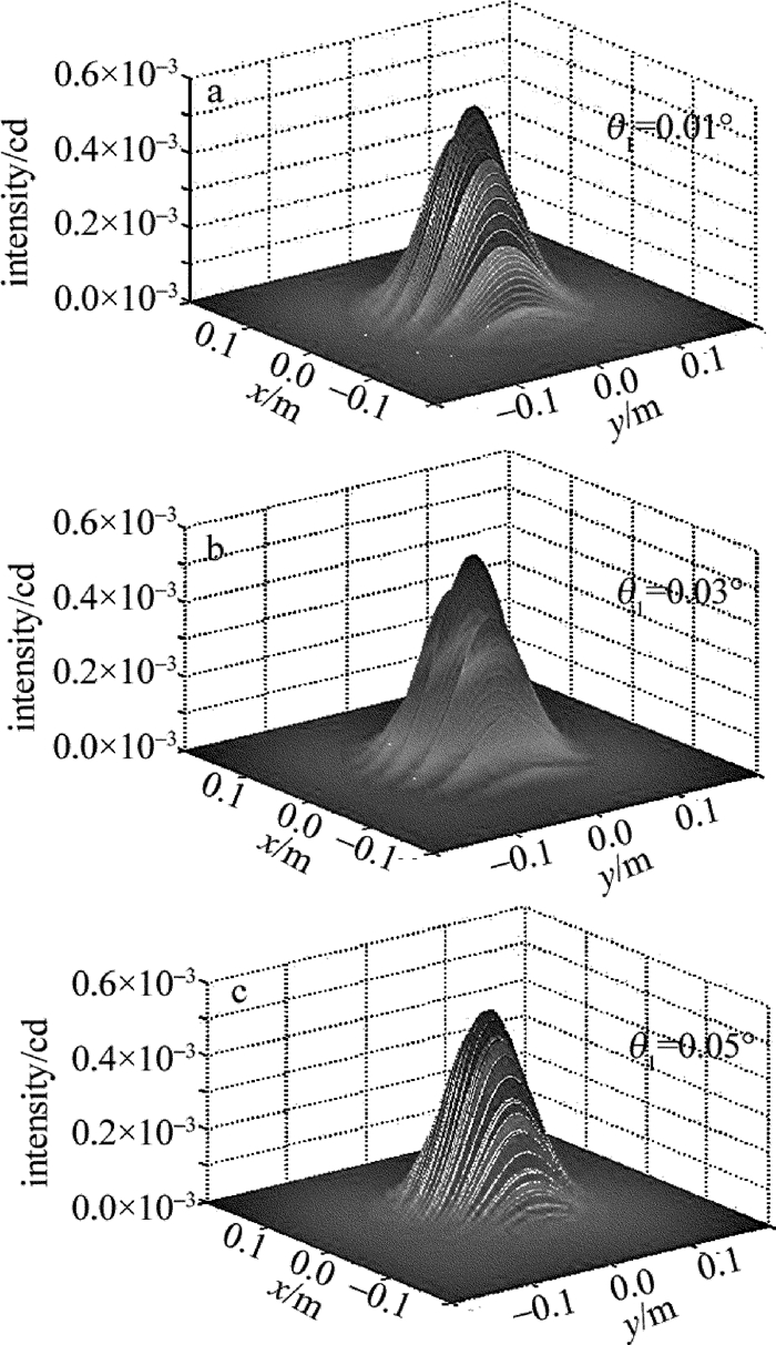
初始条件为高斯光束的束腰半径w0=1mm,传输距离L=500m,激光波长λ=532nm,马赫-曾德尔干涉光发射装置的透镜间距l=0.05m,光束沿x轴、y轴的扫描角速度分别为ωx=0rad/s,ωy=0.01rad/s,扫描时间t=5×10-4s,将设置参量带入(12)式,则有θ1≤0.08°时,能够获得远场干涉图样。图 3为远场干涉光强分布与分束镜旋转角度的变化关系。如图 3所示,在传输距离一定时,分束镜旋转角的角度发生微小变化时,远场相干光斑大小几乎无差别,但干涉图样变化明显,且条纹间距随旋转角度增大而减小,这一变化特点由3维相干光强图可明显看出。远场探测时,可以利用这一变化特性,根据探测目标的尺寸大小,合理调节分束镜旋转角度可以获得理想的条纹间距。
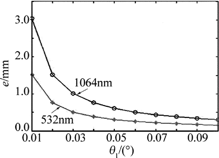
图 4为波长分别为532nm和1064nm的两种波长的高斯光束远场干涉图样的条纹间距与分束镜旋转角度的定量关系。由图 4可知,条纹间距随分束镜旋转角度增大而减小,这一规律与上面远场相干光强分布与分束镜旋转角度的变化规律是一致的。此外,当旋转角度相同时,波长为1064nm比波长为532nm的高斯光束的条纹间距大,同时其随旋转角度的变化速率也更快。因此,可以利用这一定量关系,结合目标尺寸,对旋转角度进行精确选取,当目标尺寸较大时,可以考虑使用波长较大的激光光源。
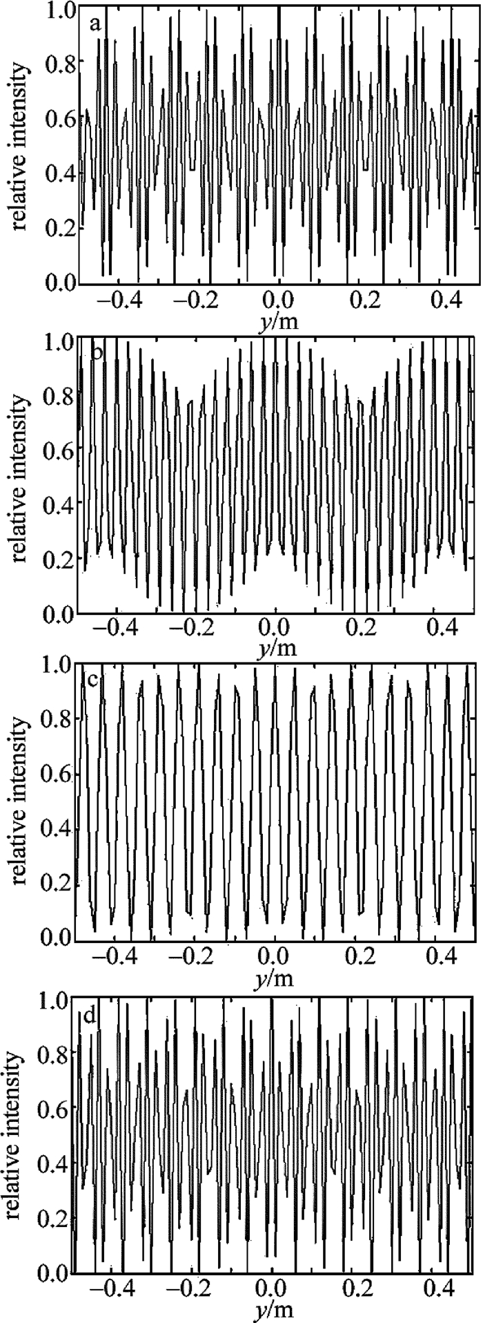
图 5为分束镜旋转角度对远场相干光条纹对比度的影响情况。如图 5所示,远场相干光条纹的对比度并没有随着旋转角度的增大呈现规律性的变化,但从图中不难看出,当θ1=0.01°时,接收屏上存在某些点附近光强的相对变量η的差值较小,对比度在0.3~0.4左右,在远场探测时,条纹对比度较小会造成回波信号的丢失,从而影响目标探测与识别的精度。当θ1适当增大时,接收屏上对比度较小的点逐渐减少,θ1=0.03°时,接收屏上每一点的对比度相同,约为0.8;θ1=0.05°时,接收屏上每一点的对比度进一步增大,可以达到0.9以上;但当θ1=0.1°时,接收屏上又出现了某些对比度较小的点,因此,在实际探测中选取分束镜的旋转角时,需要同时兼顾远场干涉图样的条纹间距和条纹对比度,在满足条纹间距要求的前提下,适当调节旋转角度,获得尽可能大的条纹对比度。
3.2 传输距离对远场相干光场分布的影响
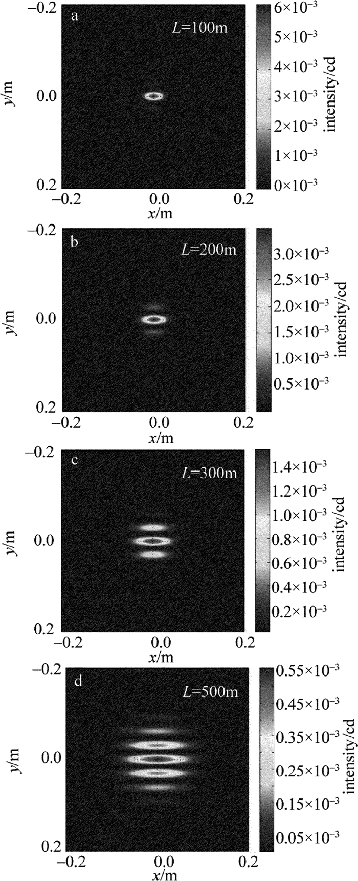
初始条件为高斯光束的束腰半径w0=1mm,θ1=0.03°,激光波长λ=532nm,马赫-曾德尔干涉光发射装置的透镜间距l=0.05m,光束沿x轴、y轴的扫描角速度分别为ωx=0rad/s,ωy=0.01rad/s,扫描时间t=5×10-4s。图 6为远场干涉光强分布与分束镜旋转角度的变化关系。如图 6所示,随着传输距离的增大,远场相干光强的分布范围变大,干涉图样的细节无明显变化,此外,干涉图样的中心光强也随着传输距离的增大明显减小。
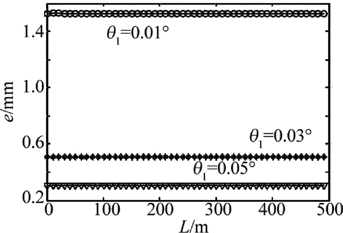
图 7为分束镜旋转角度不同时,条纹间距与传输距离的定量关系。如图 7所示,对于同一旋转角度,条纹间距随传输距离的增大无明显变化,当旋转角度增大时,远场干涉图样的条纹间距减小。条纹间距与传输距离的这一变化规律,更加方便通过单一调节干涉装置分束镜的旋转角度达到对远场干涉图样条纹间距的控制。
3.3 扫描角速度对远场相干光场分布的影响
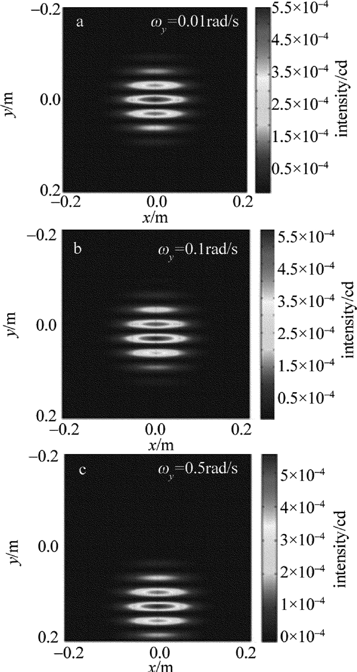
初始条件为高斯光束的束腰半径w0=1mm,θ1=0.03°,L=500m,激光波长λ=532nm,马赫-曾德尔干涉光发射装置的透镜间距l=0.05m,光束沿轴的扫描角速度为ωx=0rad/s,扫描时间t=5×10-4s。图 8为扫描角速度对远场相干光场分布的影响。如图 8所示,扫描角速度的变化主要影响远场接收屏上相干光场的位置分布,对干涉图样的细节无影响,这样就保证了干涉图样在扫描过程中的稳定性,也为相干高斯光束远场扫描探测提供了可能。
4. 结论
本文中以马赫-曾德尔干涉原理为基础,提出一种利用马赫-曾德尔干涉仪中分光镜的微小偏转获得主动相干高斯光束,进而获得远场相干光场的新方法。针对基于马赫-曾德尔干涉原理的相干光发射装置发出的相干高斯光束在远场的扫描相干光场分布特性进行分析,推导了高斯光束远场扫描相干光场的解析光强分布公式,得到了高斯光束远场扫描干涉图样。利用物理光学相关原理推导了马赫-泽德干涉装置在远场的相干光光程差、干涉图样的条纹间距以及条纹对比度的表达式。结果表明,远场扫描相干光强分布主要受到分束镜旋转角度、探测距离和发射装置扫描角速度等参量影响。干涉光发射装置的分束镜旋转角度同时影响远场接收屏上干涉图样的条纹间距及条纹对比度,在实际探测中,选取分束镜的旋转角时,需要同时兼顾远场干涉图样的条纹间距和条纹对比度,在满足条纹间距目标尺寸要求的前提下,适当调节旋转角度,获得尽可能大的条纹对比度。这些结论为后面针对远场暗小目标的激光主动相干探测与识别的理论分析与实验验证提供了一定的参考和指导意义。本文中只考虑了激光在自由空间中的传输情况,当激光在大气环境中传输时,大气湍流会对激光传输产生一系列非线性作用,如闪烁效应、漂移效应和光束展宽,这些影响在实际探测中都是不能忽视的。
-
-
[1] LECOCQ C, DESHORS G, LADO-BORDOWSKY O, et al. Sight laser detection modeling[J]. Proceedings of the SPIE, 2003, 5086:280-286. DOI: 10.1117/12.486055
[2] ZHAO Y Zh, SUN H Y, SONG F H, et al. Research and prospect of cat-eye effect used for active laser detection technique[J]. Laser & Optoelectronics Progress, 2010, 47(10):102802(in Chinese).
[3] ZHAO X J, GAO Zh Y, ZHANG Y Y. Technique of active laser reconnaissance and the applications in the military[J]. Optical Technique, 2003, 29(4):415-417(in Chinese). http://en.cnki.com.cn/Article_en/CJFDTOTAL-GXJS200304009.htm
[4] QIN K, HAN Sh K, LIU J N. Evaluation and analysis to the "cat's eye" effect in typical optical observation window[J]. Optical Technique, 2010, 36(3):391-394(in Chinese). http://ieeexplore.ieee.org/xpls/abs_all.jsp?arnumber=4821013
[5] ZHAO Y Zh, SUN H Y, SONG F H, et al. Research on the mechanism of reflection characteristics of laser irradiation on the cat eye optical lens[J]. Acta Physica Sinica, 2008, 57(4):2284-2294(in Ch-inese). http://en.cnki.com.cn/Article_en/CJFDTOTAL-WLXB200804048.htm
[6] ZHAO Y Zh, SUN H Y, SONG F H, et al. Propagation properties of oblique and off-axial Gaussian beams passing through cat-eye optical lens[J]. Acta Optica Sinica, 2009, 29(9):2252-2556(in Chinese). http://en.cnki.com.cn/article_en/cjfdtotal-gxxb200909043.htm
[7] ZHAO Y Zh, SONG F H, SUN H Y, et al. Laser reflection characteristics of cat eye effect of Cassegrain lens[J]. Chinese Journal of Lasers, 2008, 35(8):1149-1155(in Chinese). DOI: 10.3788/JCL
[8] ZHAO Y Zh, SUN H Y, SONG Zh, et al. Three-dimensional analytical formula for oblique and off-axis Gaussian beams propagating through a cat-eye optical lens[J]. Chinese Physical Letters, 2010, 27(3):034101. DOI: 10.1088/0256-307X/27/3/034101
[9] LIU B, TAO W, KE Z G, et al. Balance coherent detection technology of coherent lidar[J]. Laser Technology, 2015, 39(1):46-49(in Chinese). http://www.en.cnki.com.cn/Article_en/CJFDTotal-JGJS201501009.htm
[10] LI F D, GUO H N, SUN J G, et al. Simulation and experimental study on coherent combination of dual beam fiber laser[J]. Laser Technology, 2014, 38(4):509-514(in Chinese). http://en.cnki.com.cn/Article_en/CJFDTotal-JGJS201404015.htm
[11] HE B, LOU Q H, ZHOU J, et al. High power coherent beam combination from two fiber laser[J]. Journal of the Optical Society of America, 2006, 14(7):2721-2726. http://d.old.wanfangdata.com.cn/NSTLHY/NSTL_HYCC026190439/
[12] ZHAO Y Zh, SUN H Y, ZHENG Y H, et al. Theoretical analysis of scanning and identifying cat-eye target with coherently combined array Gaussian beams[J]. Acta Optica Sinica, 2011, 31(4):102-108(in Chinese). http://en.cnki.com.cn/Article_en/CJFDTOTAL-GXXB201104020.htm
[13] SUN X J, ZHAO Zh M. Theoretically analysis for all-fiber Mach-Zehnder interferometer based on interference analysis method[J]. Journal of Shandong TV University, 2010(1):66-67(in Chinese). http://en.cnki.com.cn/Article_en/CJFDTOTAL-SDDD201001027.htm
[14] QI H Q, DUAN K L, PU J X. Interference fringes of coherent combining fiber lasers[J]. Laser Technology, 2009, 33(2):187-190(in Chinese). http://www.opticsjournal.net/abstract.htm?aid=OJ100228000447TpVsYu
[15] CAI Y J, ZHU Sh Y. Coincidence imaging and interference with coherent Gaussian beams[J]. Acta Sinica Quantum Optica, 2005, 11(4):139-144(in Chinese). http://d.old.wanfangdata.com.cn/Periodical/zggdxxxswx-wlx200602011
[16] LIANG Q T. Physical optics[M]. 4rd ed. Beijing:Publishing House of Electronics Industry, 2012:74-76(in Chinese).
-
期刊类型引用(2)
1. 杨翠, 吴冰, 樊炳倩. 基于数学分析的高斯光束光斑半径测量方法. 激光杂志. 2020(07): 194-198 .  百度学术
百度学术
2. 靳龙, 张兴强. 圆形周期介质内艾里光束的传输特性. 激光技术. 2019(03): 432-436 .  本站查看
本站查看
其他类型引用(1)


 下载:
下载:
