Optimization design of optical antenna with wide field-of-view high-gain subwavelength structure
-
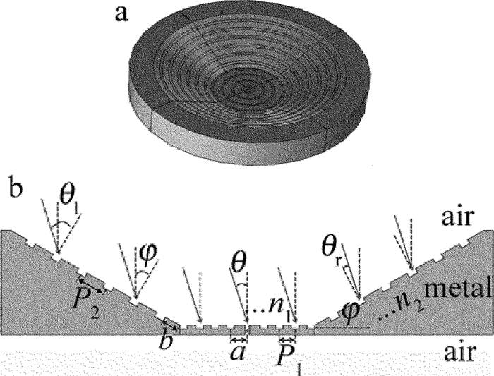
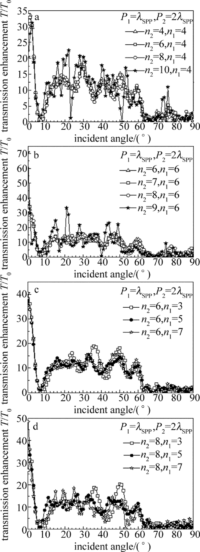
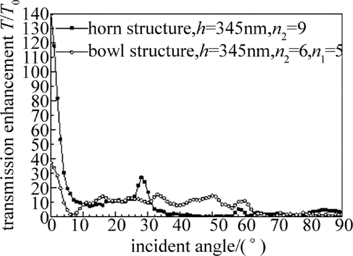
摘要: 为了优化设计自由空间的高增益广角集光天线,采用有限元数值计算方法分析不同结构参量对“牛眼”结构、喇叭型结构及碗型结构的透射增强特性的影响,得到了凹槽个数与3种结构的表面等离子体异常透射增强系数之间的关系,获得了碗型亚波长结构光学天线的透射增强优化结构参量。结果表明,在单个凹槽结构能够有效激发表面等离子基元时,喇叭型结构光学天线的透射增强系数得到有效提高;通过结构参量优化,当入射角在±5°内时,喇叭型结构的透射增益倍数为20倍~140倍,在±5°~±26°之间获得较为平坦的增益,平均透射增强系数为10,和现有的结构参量相比,性能提高1倍;碗型结构在入射光为±60°的范围内有着较好的透射增强特性,平滑区的平均透射增强系数为10。碗型结构比喇叭结构具有更加出色的广角传输特性。Abstract: In order to optimize the design of wide field-of-view high-gain optical antenna in free space, the finite element method was utilized to analyze the effect of different structure parameters on transmission enhancement characterization of bull's eye structure, horn-shaped structure and bowl-shaped structure respectively. The relationship between the numbers of slit and the coefficient of surface-plasmon-enhanced extraordinary transmission was obtained, and the optimal structure parameters of bowl-shaped optical antenna with subwavelength structure was gotten. The results show that for horn-shaped optical antenna, when the single silt can excite the strongest surface plasmon polaritons(SPP), the coefficient of transmission enhancement has lager value. By optimizing the structural parameters, the value of horn-shaped structure enhancement coefficient varies from 20 times to 140 times when the incident angle θ is within ±5°. The smooth enhanced gain is gotten at the incident angle in the range from ±5°to ±26°. The average value of the enhancement coefficient is 10. The performance is doubled compared with the performance of present structural parameters. Bowl-shaped structure has a good enhanced transmission character at the incident angle in the range of ±60° and the average value of the enhancement coefficient is 10 in the smooth enhanced transmission area. The wide field-of-view transmission character of the bowl-shaped is better than of the horn-shaped.
-
-
-
[1] BLOOM S, KOREVAAR E, SCHUSTER J, et al. Understanding the performance of free-space optics[J]. Journal of Optical Networking, 2003, 2(6):178-200. http://www.opticsinfobase.org/abstract.cfm?uri=jon-2-6-178
[2] CAI L, LI G Y, XU A Sh. Wide field-of-view free-space optical receiver based on surface plasmon polaritons[J].China Communications, 2009, 6(3):53-59(in Chinese). http://www.cnki.com.cn/Article/CJFDTotal-ZGTO200903027.htm
[3] RAMIREZ-INIGUEZ R, GREEN R J. Optical antenna design for indoor optical wireless communication systems[J]. International Journal of Communication Systems, 2005, 18(3):229-245. DOI: 10.1002/(ISSN)1099-1131
[4] JEONG W, KAVEHRAD M, JIVKOVA S. Broadband infrared access with a multi-spot diffusing configuration:performance[J]. International Journal of Wireless Information Networks, 2001, 8(1):27-36. DOI: 10.1023/A:1011381528988
[5] EBBESEN T W, LEZEC H J, GHAEMI H F, et al. Extraordinary optical transmission through subwavelength hole arrays[J]. Nature, 1998, 391(6668):667-669. DOI: 10.1038/35570
[6] LI G Y, CAI L, XIAO F, et al. Plasmonic corrugated horn structure for optical transmission enhancement[J]. Chinese Physics Letters, 2009, 26(12):124205. DOI: 10.1088/0256-307X/26/12/124205
[7] ZHANG X F, YUAN M H. Analysis of terahertz wave through a slit with parallel grooves on both sides[J]. Laser Technology, 2013, 37(4):533-536(in Chinese). http://www.wanfangdata.com.cn/details/detail.do?_type=perio&id=jgjs201304026
[8] JANSSEN O T, URBACH H P, 'THOOFT G W. On the phase of plasmons excited by slits in a metal film[J]. Optics Express, 2006, 14(24):11823-11832. DOI: 10.1364/OE.14.011823
[9] BERENGER J P. A perfectly matched layer for the absorption of electromagnetic waves[J]. Journal of Computational Physics, 1994, 114(2):185-200. http://dl.acm.org/citation.cfm?id=1718399
[10] RAKIC A D, DJURISIC A B, ELAZAR J M, et al. Optical properties of metallic films for vertical-cavity optoelectronic devices[J]. Applied Optics, 1998, 37(22):5271-5283. DOI: 10.1364/AO.37.005271
[11] JANSSEN O T, URBACH H P, 'THOOFT G W. Giant optical transmission of a subwave-length slit optimized using the magnetic field phase[J]. Physical Review Letters, 2007, 99(4):043902. DOI: 10.1103/PhysRevLett.99.043902
[12] DEGIRON A, EBBESEN T W. Analysis of the transmission process through single apertures surrounded by periodic corrugations[J]. Optics Express, 2004, 12(16):3694-3700. DOI: 10.1364/OPEX.12.003694
[13] MARTIN-MORENO L, GARCIA-VIDAL F J, LEZEC H J, et al. Theory of highly directional emission from a single subwavelength aperture surrounded by surface corrugations[J]. Physical Review Letters, 2003, 90(90):167401. http://www.wanfangdata.com.cn/details/detail.do?_type=perio&id=c1211eaa95d9791e4c43d4dba2658508
[14] GARCIA-VIDAL F J, LEZEC H J, EBBESEN T W, et al. Multiple paths to enhance optical transmission through a subwavelength slit[J]. Physical Review Letters, 2003, 90(21):213901. DOI: 10.1103/PhysRevLett.90.213901
[15] YU L B, LIN D Zh, CHEN Y Ch, et al. Physical origin of directional beaming emitted from a subwavelength slit[J]. Physical Review, 2005, B71(4):041405. http://adsabs.harvard.edu/abs/2005PhRvB..71d1405Y
[16] ISHI T, FUJIKATA J, OHASHI K. Large optical transmission through a single subwavelength hole associated with a sharp-apex grating[J]. Japanese Journal of Applied Physics, 2005, 44(4):L170-L172. DOI: 10.1143/JJAP.44.L170
[17] LI G Y, XU A Sh. Phase shift of plasmons excited by slits in a metal film illuminated by oblique incident TM plane wave[J]. Proceedings of the SPIE, 2008, 7135:71350T. DOI: 10.1117/12.803469
[18] NESCI A, DÄNDLIKER R, HERZIG H P. Quantitative amplitude and phase measurement by use of a heterodyne scanning near-field optical microscope[J]. Optics Letters, 2001, 26(4):208-210. http://www.wanfangdata.com.cn/details/detail.do?_type=perio&id=ab59712869603a33ecafea91d1a00b9e
[19] ZHENG Y, DU J L. Simulation of interference field of multi-beam surface plasma polaritons[J].Laser Technology, 2013, 37(1):28-31(in Chinese). http://www.wanfangdata.com.cn/details/detail.do?_type=perio&id=jgjs201301007
[20] LEZEC H J, THIO T. Diffracted evanescent wave model for enhanced and suppressed optical transmission through subwavelength hole arrays[J]. Optics Express, 2004, 12(16):3629-3651. DOI: 10.1364/OPEX.12.003629
-
期刊类型引用(9)
1. 孔彦坤,邓伟,金国忠,雷基林,陈丽琼,贾德文. 36MnVS4和46MnVS5连杆裂解性能差异性研究及质量缺陷分析. 中国机械工程. 2024(06): 1103-1111+1119 .  百度学术
百度学术
2. 刘友健,雷智洪,吴俊伟,陈燕,纪轩荣. 超快激光制备高频1-3型PIN-PMN-PT复合材料超声换能器. 压电与声光. 2023(02): 288-293 .  百度学术
百度学术
3. 王冠,陈国华,诸杰煜,汪春辉. 激光加工工艺参数对36MnVS4连杆切槽质量影响研究. 激光杂志. 2023(08): 198-205 .  百度学术
百度学术
4. 林晓平,王冠,张冲,汪春辉,刘赞丰,张雅文. 光纤激光垂直加工连杆裂解槽装备设计. 组合机床与自动化加工技术. 2022(03): 134-137 .  百度学术
百度学术
5. 张冲,王冠,刘赞丰,张雅文. 激光微加工对Ti6Al4V表面形貌及润湿性影响的研究. 激光技术. 2021(01): 31-36 .  本站查看
本站查看
6. 赵士伟,张海云,李志永,赵玉刚,张晋烨. 激光参量对血管支架切缝形貌及粗糙度的影响. 激光技术. 2020(03): 299-303 .  本站查看
本站查看
7. 寇淑清,修亭亭,金文明,赵勇,姚娟. 后桥主减速器壳体轴承座材料裂解性能数值分析. 华南理工大学学报(自然科学版). 2019(07): 121-127+135 .  百度学术
百度学术
8. 郭树霞. 改进蚁群算法下激光切割加工工艺优化研究. 机电信息. 2019(24): 94-95 .  百度学术
百度学术
9. 赵三军,赵水,张志强,贾斌,陈绍磊,周玉梅,姜冰,吴军. 激光切割8 mm厚锰钢板的工艺试验研究. 制造技术与机床. 2019(09): 70-73 .  百度学术
百度学术
其他类型引用(7)


 下载:
下载:
