
Preparation of Ti-Al-N composite coating by laser cladding AlN/TiAl and study of its wear performance
-
摘要:
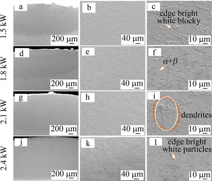
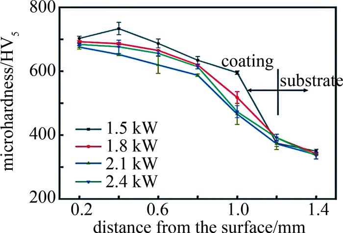
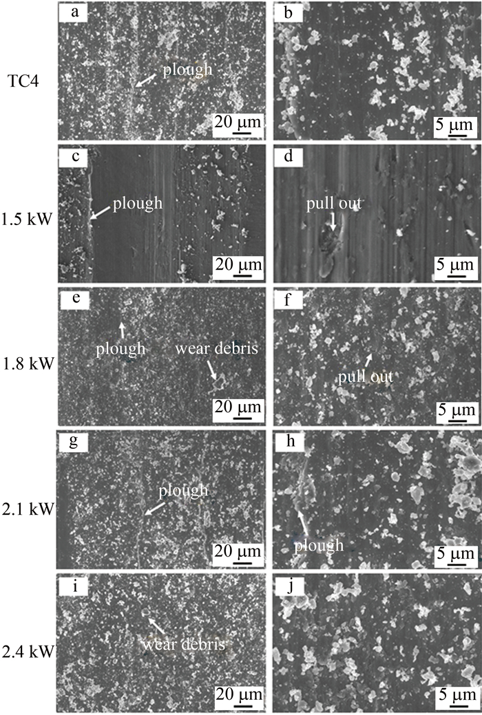
为了制备耐磨钛基涂层,采用激光熔覆技术在TC4表面制备了Ti-Al-N涂层,对不同激光功率下涂层的物相组成、组织演变、硬度进行观察分析,再对复合涂层在空气环境中的摩擦学性能进行分析。结果表明,涂层增强相主要由Ti2AlN, TiN, TiAl及TixAly等组成,各物相衍射峰强度随激光功率的增加而改变,基体相则由(γ-TiAl+α2-Ti3Al)组成;涂层与基体冶金结合,随着激光功率的增加,组织由弥散分布的柱状晶逐渐变成粗大树枝晶,但在2.4 kW功率时,组织又变得细小;复合涂层的显微硬度可以达到基体的2.14倍;在空气摩擦环境中,不同试样均以磨粒磨损为主,其中基体磨损严重;不同激光功率下的涂层均大幅度提高了基体的耐磨性,涂层中有增强相的存在,涂层的最小磨损率为0.786×10⁻⁴ mm3·N-1·min-1,基体为1.34×10⁻⁴ mm3·N-1·min-1;通过控制激光功率可以调节涂层性能。这一研究可以对激光熔覆制备高耐磨钛基复合涂层在航天、海工设备中的应用提供基础支持。
-
关键词:
- 激光技术 /
- 钛合金 /
- 激光熔覆 /
- Ti-Al-N复合涂层 /
- 干摩擦磨损
Abstract:In order to prepare wear-resistant titanium-based coating, a Ti-Al-N wear-resistant titanium-based coating was prepared on TC4 surface by laser cladding. The phase composition, microstructure evolution and hardness of the coating under different laser powers were observed and analyzed, and then the tribological properties of the composite coating in the air environment were analyzed. The results show that the strengthening phase of the coating is mainly composed of Ti2AlN, TiN, TiAl and TixAlly. The diffraction peak intensity of each phase changes with the increase of laser power, and the matrix phase is composed of (γ-TiAl+α2-Ti3Al). The coating is metallurgically bonded to the substrate. With the increase of laser power, the microstructure gradually changes from dispersed columnar crystals to coarse dendrites, but when the laser power was 2.4 kW, the microstructure becomes fine again. The microhardness of the composite coating can reach 2.14 times that of the substrate. In the air friction environment, different samples are mainly abrasive wear, and the matrix wear is serious. The coatings under different laser powers greatly improve the wear resistance of the substrate. The minimum wear rate of the coating was 0.786×10⁻⁴ mm3· N-1·min-1, and the matrix was 1.34×10⁻⁴ mm3·N-1·min-1. Therefore, the coating performance can be adjusted by controlling the laser power, which provides basic support for the application of laser cladding high wear-resistant titanium-based composite coatings in aerospace and marine equipment.
-
引言
粘接是指通过具有粘附能力的物质,将材料连接在一起的方法[1]。相比于机械连接,粘接具有质量轻、应力分布均匀、耐腐蚀等优点,是一种理想的轻量化连接技术[2]。粘接区域的表面质量是影响粘接性能的重要因素之一,合适的表面处理方法可以去除表面污染物和氧化层[3],提高表面湿润性和粗糙度,使粘接剂和基底紧密接触,并形成机械互锁[4]和界面分子的化学作用[5],获得优异的粘接性能。粗糙的界面也可以阻止有害物体的入侵,增加接头的环境耐久性[6]。常规的表面处理方法有:机械打磨[7]、喷砂[8]、电化学腐蚀[9]和等离子处理[10]。随着激光技术的发展,激光表面处理具有高效、环保、自动化等优点[11]。通过控制激光参量优化粘接区域的表面形貌,提高粘接性能[12]。铝合金具有比强度高、力学性能良好等优点[13],铝合金粘接被广泛应用于对轻量化要求较高的汽车领域[14],因此,激光处理提高铝合金粘接性能的研究具有重要意义。
WU等人[15]研究了激光能量密度对AA6022-T4粘接接头性能的影响,结果表明,相比于原始材料,较高的能量密度(19.01J/cm2)处理使接头强度增加25%,并增加了浸水暴露后内聚破坏模式的程度;较低的能量密度(小于19.01J/cm2)可以去除表面污染物。ROMOLI等人[16]研究激光表面纹理对铝合金粘接强度的影响,结果表明,接触面积增加可以促进基体和粘接剂的机械互锁,但过大的粗糙度和深度会使气泡进入纹理深处,削弱粘接强度的提高。
激光加工参量对7075-T6铝合金基底粘接强度的影响尚未得到深入研究,作者利用纳秒光纤脉冲激光加工铝基板,建立单脉冲能量与所形成烧蚀烧蚀坑直径及深度的关系,通过控制脉冲能量和烧蚀坑重叠率在粘接区域形成阵列微结构,研究不同参量对表面形貌和粘接强度的影响,探究断裂模式影响剪切强度的机理。
1. 实验
1.1 实验材料
实验材料为7075-T6铝基板和3M DP460双组份常温固化环氧胶。表 1和表 2中分别为材料的力学性能参量。
Table 1. Mechanical properties of 7075-T6material Poisson’s ratio elastic modulus/GPa yield strength/MPa tensile strength/MPa elongation/ % 7075-T6 0.33 65 515 580 15 Table 2. 3M DP460 mechanical properties after curingmaterial Poisson’s ratio elastic modulus/GPa tensile strength/MPa shear strength/MPa 3M DP460 0.04 2.7 37 32 1.2 激光加工烧蚀坑阵列微结构
表 3中为激光器的参量。脉冲能量E主要由脉冲频率ƒ、脉冲宽度τ和最大功率百分比η控制,加工时保持ƒ=10kHz、τ=200ns;单脉冲位置主要由扫描速率v和扫描间距H控制。
Table 3. Parameters of laserparameter value laser medium Yb-fiber pulse energy profile nearly Gaussian wavelength λ 1064nm focal spot diamete d 35μm percentage of maximum power density η 0%~100% pulse durtion time τ 4ns~200ns pulse frequency f 0kHz~1000kHz beam scanning speed v 0mm/s~2000mm/s beam scanning distance H 0mm~300mm 图 1为激光烧蚀坑阵列微结构的示意图。图中,D为烧蚀坑直径,δv和δH分别为扫描速率和扫描间距方向的烧蚀坑重叠率, δv由v、ƒ和D共同确定,δH由H和D共同确定。在加工激光烧蚀坑阵列微结构时保持δv=δH,则加工参量需要满足下式:
δ=(1−v/Df)×100%=(1−H/D)×100% (1) 式中,δ为烧蚀坑重叠率。单个烧蚀坑的直径D仅与E相关,故ƒ=10kHz不变时,烧蚀坑阵列微结构可仅由E和δ确定。因此,在加工烧蚀坑阵列微结构之前,首先需要确定E和D之间的关系,然后根据所需的E和δ,通过(1)式计算得到激光加工时所需的v和H。激光加工之前,所有基板均在超声水浴中清洗5min,以去除基板表面的油污及灰尘。此外,使用表面未经激光处理的样品作为参考组。
1.3 单塔接试样件的制作以及准静态拉伸剪切测试
图 2a为单塔接试样的几何尺寸。基板尺寸为101.6mm×25.4mm×1.5mm,粘接区域的面积为25.4mm×12.7mm。图 2b为单塔接试样件的制作装置。其中,采用超声水浴清洗去除激光加工的残留物[17];在粘接剂中添加少量直径为0.3mm的玻璃微珠来控制胶层厚度[18];试样件在25℃下固化72h;每组参量制作5个试样。图 2c为准静态拉伸剪切测试。使用最大载荷为100kN的电子万能试验机,根据ASTM D1002-2001标准来测量接头的拉伸剪切强度[19],拉伸速率为1mm/min。
接头的剪切强度σ由下式得到:
σ=F/S (2) 式中,F是接头断裂前的最大载荷(单位为N),S是粘接区域的面积(25.4mm×12.7mm)。
1.4 表面形貌和断裂模式表征
使用扫描电镜(HITACHI TM3030)观察表面形貌,使用激光共聚焦显微镜(OLYMPUS OLS4000)计算表面粗糙度Ra和表面面积增加比Rs,每个样品随机选择5个位置测量[20]。单塔接剪切测试后,使用扫描电镜观察接头典型断面。
2. 结果与讨论
2.1 激光加工烧蚀坑参量选择
首先使用激光功率计测量不同η下平均功率P,然后通过下式计算得到单个光斑的E(ƒ=10kHz):
E=P/f (3) 表 4中为单光斑脉冲能量参量。图 3为单个烧蚀坑的表面形貌和截面轮廓线图。其中图 3a、图 3b和图 3c分别是E为176μJ,528μJ和880μJ的烧蚀坑,图 4为图 3a、图 3b和图 3c的截面轮廓线。D和V分别为烧蚀坑的直径和深度。由图 3a、图 3b和图 3c可以看出,烧蚀坑是通过基板材料熔化、热毛细对流及汽化形成的。由图 4可以看出,烧蚀坑呈中间深边缘浅的“陨石坑”形状,且随着E的增大,D和V分别增大。
Table 4. Single spot pulse energy parameterη/% 10 20 30 40 50 60 70 80 90 100 P/W 0.88 1.76 2.64 3.52 4.40 5.28 6.16 7.04 7.92 8.80 E/μJ 88 176 264 352 440 528 616 704 792 880 图 5为单个脉冲能量下的烧蚀坑直径D和深度V。当E较小时,D和V随着E的增加呈线性增加,因为较高的E可以产生更大的熔池。当E增大到一定值时,D和V的增长逐渐减慢,特别是当E相对较高时,D和V的值逐渐饱和。
后面实验中,选取E为176μJ,528μJ,880μJ和δ为0%,30%,60%加工烧蚀坑阵列微结构。表 5中为通过(1)式计算得到的激光加工所需的参量。
Table 5. Laser processing parameterpulse energy E/μJ ablation crater diameter D/μm ablation crater overlap rate δ/% scanning speed v/(mm·s-1) scanning pitch H/μm 0 467 46.77 176 46.77 30 327 32.74 60 187 18.71 0 654 65.42 528 65.42 30 458 45.79 60 262 26.17 0 730 73.01 880 73.01 30 511 51.11 60 292 29.20 2.2 脉冲能量和烧蚀坑重叠率对表面形貌的影响
图 6a显示了不同脉冲能量E下表面粗糙度Ra与烧蚀坑重叠率δ的关系。没有激光处理时,Ra=0.31μm。当δ一定时,Ra随E几乎无变化,这表明E对Ra几乎无影响;当E一定时,Ra随δ的变化较大,Ra先随δ的增大而大幅减小,δ=30%之后,Ra稍许增大,这表明δ是Ra的主要影响因素。图 6b显示了不同E下表面面积增加比Rs与δ的关系。没有激光处理时Rs=1.22。可以看出,当δ一定时,Rs随E变化较小,这表明E对Rs影响较小;当E一定时,Rs随δ的变化较大,Rs随着δ的增加而增加,这表明δ是Rs的主要影响因素。
![Figure 6. Surface roughness and developed interfacial area ratio]() Figure 6. Surface roughness and developed interfacial area ratioa—surface roughness b—developed interfacial area ratio
Figure 6. Surface roughness and developed interfacial area ratioa—surface roughness b—developed interfacial area ratio图 7为不同脉冲能量E和烧蚀坑重叠率δ的基底截面轮廓线图。由图 7可以看出,当δ相同时,随着E的增加,烧蚀坑的深度相对变化不明显,直径变大,数量减少,3种因素叠加导致E对Ra几乎无影响。
由于E对Ra几乎无影响,对E=176μJ时的基底表面形貌和扫描电镜(scanning electron microscope, SEM)图进行分析。图 8a为材料原始表面形貌,表面平整,Ra最小。图 8b为δ=0%时的表面形貌,表面存在未处理区域,高度差大,Ra最大。图 8c为δ=30%时的表面形貌,表面被完全处理,表面落差小,相比δ=0%时,Ra大幅降低。图 8d为δ=60%时的表面形貌,大量表面区域被重复加工,熔融残留物较多,相比δ=60%时,Ra稍许增加。图 8b中截面1的参量为E=176μJ,δ=0%。图 6讨论的其它参量的截面位置同理,分别平行于xz轴组成的平面并穿过烧蚀坑中心。由图 8d中SEM图可以看出,当E=176μJ时,表面具有明显的孔洞特征,这是影响Rs的主要因素。由于脉冲宽度不变,即作用在材料的时间不变,则E=528μJ和E=880μJ时,同样形成类似的孔洞特征,所以E对Rs影响较小。由图 8可以看出,随着δ的增加,表面被重复处理区域越多,凹凸和孔洞特征越明显,即Rs随着δ的增加而增加。
![Figure 8. Surface topography and SEM images of substrate]() Figure 8. Surface topography and SEM images of substratea—untreated, E=176μJ b—δ=0% c—δ=30% d—δ=60%
Figure 8. Surface topography and SEM images of substratea—untreated, E=176μJ b—δ=0% c—δ=30% d—δ=60%2.3 脉冲能量和烧蚀坑重叠率对剪切强度的影响
图 9为不同脉冲能量E和烧蚀坑重叠率δ下接头的剪切强度σ。当δ一定时,σ几乎不随E变化,这表明E对σ几乎无影响;当E一定时,σ随δ的变化较大,σ先随δ的增大而增大,δ=30%之后,σ随δ的增大而减小,这表明δ是σ的主要影响因素。另外, 未经激光处理时,σ=10MPa,激光处理后的σ至少提升了150%;当E=880μJ,δ=30%时,σ=27.76MPa,提升最大。
2.4 接头断裂模式分析
接头失效后,粘接区域有界面断裂、内聚断裂(粘 接剂断裂)和基体断裂[21]3种断裂模式。内聚断裂是优选的,因为能量耗散主要发生在粘接剂中,从而提高了接头强度和韧性[22]。当完全发生内聚断裂时,接头的强度最接近于粘接剂自身的强度,此时接头的强度由粘接剂的强度决定。
由于E对σ几乎无影响,对E=176μJ的接头断裂模式进行分析,并揭示δ影响σ的机理。图 10为接头断面的宏观照片及典型区域的SEM图。其中区域1和区域2分别与区域3和区域4相对应。从宏观照片可以看出,无论δ取何值时,断裂面都发生了混合断裂(至少有两种断裂模式)。通过SEM进一步判断典型的断裂模式。如图 10a所示,当δ=0%时,区域1的断裂模式为界面断裂,区域2中烧蚀坑内部的断裂模式为内聚断裂,外部的断裂模式为界面断裂。如图 10b所示,当δ=30%时,区域1的断裂模式为主要为界面断裂,区域2断裂模式为内聚断裂。如图 10c所示,当δ=60%时,区域1的断裂模式为基体断裂,区域2断裂模式为内聚断裂。通过对比可知:当δ=30%时,粘接区域发生内聚断裂断的面积最大,仅有少部分区域发生了界面断裂; 当δ=0%时,烧蚀坑外部未经激光处理的区域易发生界面断裂,这使得粘接区域发生界面断裂的面积比δ=30%时有所增加,因此σ相比δ=30%时有所减小; 当δ=60%时,大部分粘接区域发生了基体断裂,仅有少许区域发生了内聚断裂, 这使得σ相比δ=30%时有所减小。
![Figure 10. Macro section of joint and SEM images of typical section E=176μJ]() Figure 10. Macro section of joint and SEM images of typical section E=176μJa—δ=0% b—δ=30% c—δ=60%
Figure 10. Macro section of joint and SEM images of typical section E=176μJa—δ=0% b—δ=30% c—δ=60%综上可知:当δ较小时(小于30%),未被激光加工的区域易发生界面断裂,会对σ产生负面的影响;随着δ的增大,激光重复加工的区域增多,使表面覆盖的熔融残留物越多,造成粘接区域易发生基体断裂,也会对σ产生负面的影响。
3. 结论
单个烧蚀坑直径D和深度V随着脉冲能量E的增加而增加,当E<528μJ时,D和V随着E呈线性增加;当E>528μJ时,D和V的增长速率逐渐减慢,并逐渐达到饱和。
表面粗糙度Ra和表面面积增加比Rs受脉冲能量E的影响不大,而受烧蚀坑重叠率δ的影响较大。具体表现为:Ra先随δ的增大而大幅减小,δ=30%之后,Ra稍许增大;Rs随着δ的增加而增加。
相比激光未处理时,激光处理后都发生混合断裂模式,剪切强度至少提升150%, 其中,E=880μJ,δ=30%时最大为27.76MPa。
剪切强度和断裂模式受脉冲能量E的影响不大,而受烧蚀坑重叠率δ的影响较大。具体表现为:当δ=30%时,粘接区域发生内聚断裂断的面积最大,剪切强度最大;当δ=0%时,粘接表面未被激光加工的区域易发生界面断裂,导致剪切强度相比δ=30%降低;当δ=60%,粘接表面大量区域被重复加工,使表面被一层熔融残留物覆盖,该区域易发生基体断裂,也会对导致剪切强度相比δ=30%降低。
-
![]()
图 1 不同激光功率下复合涂层在的XRD结果图
Figure 1. XRD results of composite coatings at different laser powers
![]()
图 2 不同功率下复合涂层的宏观形貌和微观组织形貌
Figure 2. Macroscopic morphology and microstructure morphology of composite coatings under different power
![]()
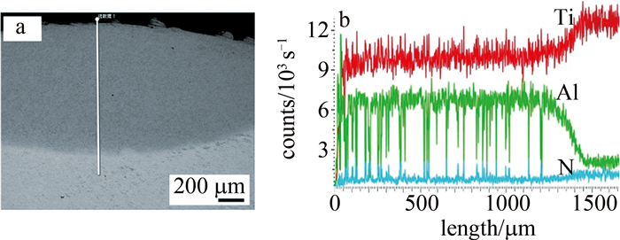
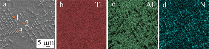
图 4 1.5 kW功率下复合涂层点扫位置和面扫结果图
Figure 4. Point scanning position and surface scanning results of the composite coating at 1.5 kW power
![]()
图 5 不同激光功率下复合涂层的显微硬度结果图
Figure 5. Microhardness results of composite coatings under different laser power
![]()
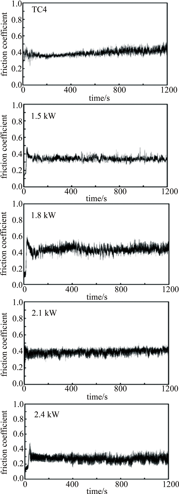
图 6 不同激光功率复合涂层在空气环境中的摩擦系数曲线图
Figure 6. Friction coefficient curves of different laser power composite coatings in three environments
![]()
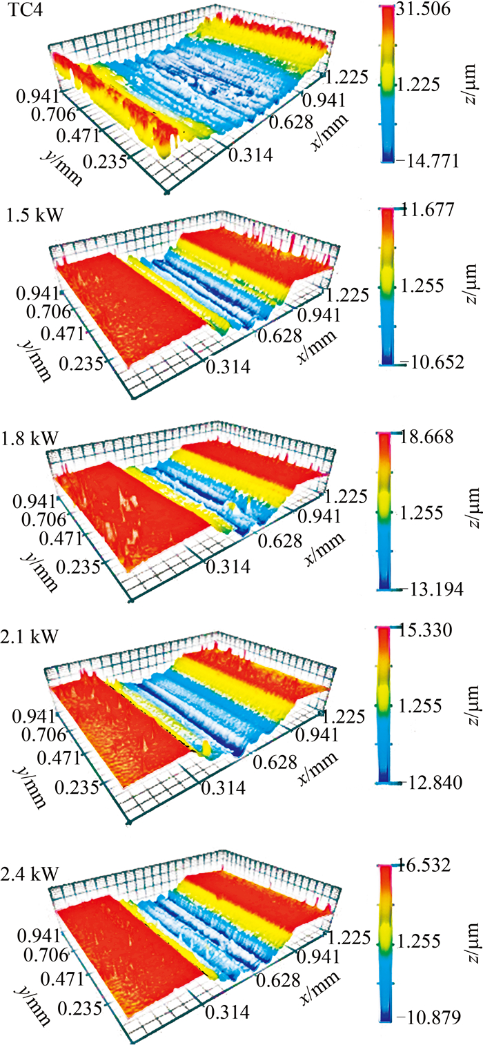
图 7 不同激光功率复合涂层在空气环境中的磨痕3-D图
Figure 7. 3-D images of wear scars of composite coatings with different laser power in three environments
![]()
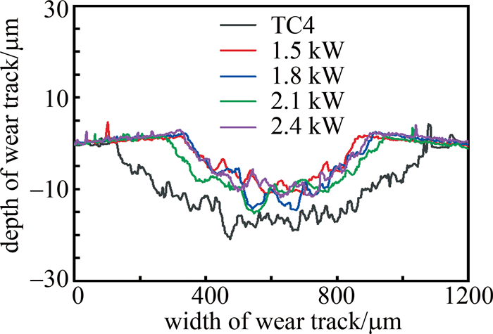
图 8 不同激光功率复合涂层在空气环境中的磨痕2-D截面图
Figure 8. 2-D cross section of wear scars of composite coatings with different laser power in three environments
![]()
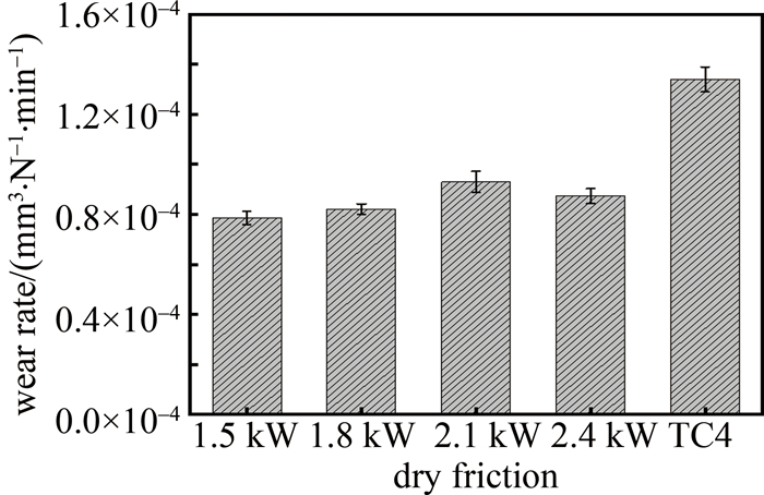
图 9 不同激光功率复合涂层在空气环境中的磨损率图
Figure 9. Wear rate of composite coatings with different laser power in three environments
![]()
图 10 不同激光功率复合涂层在空气环境中的磨痕微观图
Figure 10. Micrographs of wear scars of composite coatings with different laser power in three environments
表 1 TiAl粉末的化学成分(质量分数)
Table 1 Chemical composition of TiAl powder (mass fraction)
element Al Nb Cr O N Ti mass fraction/% 33.13 4.75 2.65 0.0846 0.0427 balance  下载: 导出CSV
表 2 钛合金表面激光熔覆不同涂层的工艺参数
Table 2 Process parameters of laser cladding different coatings on titanium alloy surface
No. powder(mass ratio) scanning speed/(mm·s-1) power/kW 1 m(TiAl)∶m(AlN)=4∶1 2 1.5 2 m(TiAl)∶m(AlN)=4∶1 2 1.8 3 m(TiAl)∶m(AlN)=4∶1 2 2.1 4 m(TiAl)∶m(AlN)=4∶1 2 2.4
下载: 导出CSV
表 3 1.5 kW涂层点扫结果
Table 3 1.5 kW coating spot scanning results (mass fraction)
position w(Ti)/% w(Al)/% w(N)/% 1 60.08 26.50 13.42 2 65.51 34.49 0.00 3 60.89 4.50 34.61
下载: 导出CSV
-
[1] WANG F R, GUO S, WANG Y Q, et al. Effect of Nb interlayer on microstructure and property of Ti-6Al-4V/690 MPa grade steel clad plate by vacuum rolling[J]. Materials Science and Engineering, 2023, A882: 145450.
[2] MA S, ZONG N, DONG Z, et al. Ti-adsorption induced strain release in promoting α-Al nucleation at TiB2-Al interfaces[J]. Applied Surface Science, 2023, 639: 158185. DOI: 10.1016/j.apsusc.2023.158185
[3] 赵扬, 杨平华, 王铭振, 等. 钛合金增材制造孔隙缺陷的无损检测研究进展[J]. 激光技术, 2024, 48(3): 432-437. DOI: 10.7510/jgjs.issn.1001-3806.2024.03.020 ZHAO Y, YANG P H, WANG M Zh, et al. Research progress of nondestructive testing of pore defects in titanium alloy additive manufacturing[J]. Laser Technology, 2024, 48(3): 432-437(in Ch-inese). DOI: 10.7510/jgjs.issn.1001-3806.2024.03.020
[4] YE Y, WANG Y, WANG C, et al. An analysis on tribological performance of CrCN coatings with different carbon contents in seawater[J]. Tribology International, 2015, 91: 131-139. DOI: 10.1016/j.triboint.2015.07.002
[5] YE Y, WANG Y, CHEN H, et al. Doping carbon to improve the tribological performance of CrN coatings in seawater[J]. Tribology International, 2015, 90: 362-371. DOI: 10.1016/j.triboint.2015.04.008
[6] WANG J, CUI X, ZHAO Y, et al. Microstructure and performance enhancement of the TiN/Fe-based cladding layer induced by mechanical vibration assisted underwater wet laser cladding[J]. Surface and Coatings Technology, 2024, 476: 130176. DOI: 10.1016/j.surfcoat.2023.130176
[7] ZHAO P, LI J, ZHANG Y, et al. Wear and high-temperature oxidation resistances of AlNbTaZrx high-entropy alloys coatings fabricated on Ti6Al4V by laser cladding[J]. Journal of Alloys and Compounds, 2021, 862: 158405. DOI: 10.1016/j.jallcom.2020.158405
[8] 赵欣鑫, 肖华强, 游川川, 等. TC4表面激光熔覆TiAl合金涂层的工艺和组织性能[J]. 激光技术, 2021, 45(6): 697-702. DOI: 10.7510/jgjs.issn.1001-3806.2021.06.004 ZHAO X X, XIAO H Q, YOU Ch Ch, et al. Process and microstructure properties of laser cladding TiAl alloy coating on TC4 surface[J]. Laser Technology, 2021, 45(6): 697-702 (in Chinese). DOI: 10.7510/jgjs.issn.1001-3806.2021.06.004
[9] ZHENG M, FAN D, LI X, et al. Microstructure and osteoblast response of gradient bioceramic coating on titanium alloy fabricated by laser cladding[J]. Applied Surface Science, 2008, 255(2): 426-428. DOI: 10.1016/j.apsusc.2008.06.078
[10] ZHANG Zh Q, YANG F, ZHANG H W, et al. Microstructure and element distribution of laser cladding TiC-reinforced CrTi4-based composite coating with CeO2/Ce2O3[J]. Materials Letters, 2021, 283(1): 128772.
[11] CARCEL B, SERRANO A, ZAMBRANO J, et al. Laser cladding of TiAl intermetallic alloy on Ti6Al4V-process optimization and properties[J]. Physics Procedia, 2014, 56: 284-293. DOI: 10.1016/j.phpro.2014.08.173
[12] van OTTERLOO J L D M, de HOSSON J T M. Microstructure and abrasive wear of cobalt-based laser coatings[J]. Scripta Materialia, 1997, 36(2): 239-245. DOI: 10.1016/S1359-6462(96)00346-6
[13] WEI M X, WANG S Q, WANG L, et al. Wear and friction characteristics of a selected stainless steel[J]. Tribology Transactions, 2011, 54(6): 840-848. DOI: 10.1080/10402004.2011.606960
[14] CAI Q, LI G, WU B, et al. Effect of TiC content on microstructure and properties of TiC/Ni60 coatings on Ti6Al4V alloy deposited by laser cladding[J]. Optics & Laser Technology, 2024, 168: 109854.
[15] LI J, CUI X, GUAN Y, et al. Analysis of oxidation behavior of laser cladding SiC-Ti based composite strengthening coating[J]. Materials Characterization, 2023, 204: 113210. DOI: 10.1016/j.matchar.2023.113210
[16] LIU H, ZHANG X, JIANG Y, et al. Microstructure and high temperature oxidation resistance of in-situ synthesized TiN/Ti3Al intermetallic composite coatings on Ti6Al4V alloy by laser cladding process[J]. Journal of Alloys and Compounds, 2016, 670: 268-274. DOI: 10.1016/j.jallcom.2015.10.168
[17] CHOI B, KIM I, LEE Y, et al. Microstructure and friction/wear behavior of (TiB+TiC) particulate-reinforced titanium matrix composites[J]. Wear, 2014, 318(1): 68-77.
[18] LI S N, XIONG H P, LI N, et al. Mechanical properties and formation mechanism of Ti/SiC system gradient materials fabricated by in-situ reaction laser cladding[J]. Ceramics International, 2017, 43(1): 961-967. DOI: 10.1016/j.ceramint.2016.10.026
[19] JIANG D, CUI H, CHEN H, et al. Wear and corrosion properties of B4C-added CoCrNiMo high-entropy alloy coatings with in-situ coherent ceramic[J]. Materials & Design, 2021, 210: 110068.
[20] MA G, ZHAO Y, CUI H, et al. Addition Al and/or Ti induced modifications of microstructures, mechanical properties, and corrosion properties in CoCrFeNi high-entropy alloy coatings[J]. Acta Metallurgica Sinica (English Letters), 2021, 34: 1087-1102. DOI: 10.1007/s40195-021-01219-z
[21] OCELIK V, MATTHEWS D, de HOSSON J T M, et al. Sliding wear resistance of metal matrix composite layers prepared by high power laser[J]. Surface and Coatings Technology, 2005, 197(2): 303-315.
[22] HAO X, LIU H, ZHANG X, et al. Microstructure and wear resistance of in-situ TiN/(Nb, Ti)5Si3 reinforced MoNbTaWTi-based refractory high entropy alloy composite coatings by laser cladding[J]. Applied Surface Science, 2023, 626: 157240. DOI: 10.1016/j.apsusc.2023.157240
[23] YAN W, ZHANG Z, ZHANG Y, et al. Research on Ti-GLC/TiCN/TiN composite multilayer coating with ultra-low friction coefficient in various environments[J]. Surfaces and Interfaces, 2021, 26: 101426. DOI: 10.1016/j.surfin.2021.101426
[24] ZHANG H, CUI H, MAN C, et al. The tribocorrosion resistance of TiN+TiB/TC4 composite coatings and the synergistic strengthening effects of multi-level reinforcements[J]. Corrosion Science, 2023, 219: 111224. DOI: 10.1016/j.corsci.2023.111224
[25] MAGNUSON M, MATTESINI M, LI S, et al. Bonding mechanism in the nitrides Ti2AlN and TiN: An experimental and theoretical investigation[J]. Physical Review, 2007, B76(19): 195127.
[26] HAN X, LIU P, SUN D, et al. An atomic-level understanding of the friction and wear behaviors of Ti2AlN/TiAl composite via MD simulations[J]. Tribology International, 2019, 137: 340-348. DOI: 10.1016/j.triboint.2019.05.021
[27] FENG J, XIAO H. Tribocorrosion behavior of laser cladded Ti-Al-(C, N) composite coatings in artificial seawater[J]. Coatings, 2022, 12(2): 187. DOI: 10.3390/coatings12020187
[28] LI C, ZENG M, LIU C, et al. Microstructure and tribological behavior of laser cladding TiAlSi composite coatings reinforced by alumina-titania ceramics on Ti6Al4V alloys[J]. Materials Chemistry and Physics, 2020, 240: 122271. DOI: 10.1016/j.matchemphys.2019.122271
[29] ZHANG X, CUI H, WANG J, et al. Effects of TiB2+TiC content on microstructure and wear resistance of Ni55-based composite coatings produced by plasma cladding[J]. Transactions of Nonferrous Metals Society of China, 2019, 29(1): 132-142. DOI: 10.1016/S1003-6326(18)64922-2
[30] 吴玉萍, 林萍华, 王泽华, 等. 多层预涂敷等离子熔覆TiC/Ni梯度涂层研究[J]. 材料热处理学报, 2004, 25(3): 74-77. WU Y P, LIN P H, WANG Z H, et al. Study on multi-layer pre-coated plasma cladding TiC/Ni gradient coating[J]. Journal of Materials Heat Treatment, 2004, 25(3): 74-77(in Chinese).
[31] JIANG M, SUN H, LIU R, et al. Fabrication and mechanical properties of Ti2AlN/TiAl composite with continuous network structure[J]. Transactions of Nonferrous Metals Society of China, 2023, 33(5): 1437-1451.
-
期刊类型引用(1)
1. 呼啸,胡建波,吕江博. 激光粘接技术在西安半坡彩陶纹服饰设计中的应用研究. 粘接. 2024(11): 9-11+15 .  百度学术
百度学术
其他类型引用(1)


计量
- 文章访问数: 8
- HTML全文浏览量: 1
- PDF下载量: 5
- 被引次数: 2