
Weld seam tracking method under strong noise based on kernel correlation filters
-
摘要:
在基于结构光视觉的焊缝跟踪中,焊接时产生的电弧和飞溅等强噪声会大幅降低焊缝的能见度,导致跟踪失败。为了解决这一问题,提出了一种基于改进核相关滤波器的焊缝跟踪算法,以更好地适应强噪声的环境。首先获取焊缝的初始特征点,基于焊缝激光条纹的灰度分布特征,通过Steger算法提取焊缝激光条纹的中心线; 接着对中心线进行滤波并求导来获取焊缝的初始特征点; 最后将焊缝的初始特征点作为初始输入,应用改进的核相关滤波器对焊缝特征点进行学习与跟踪。结果表明,在强噪声干扰的情况下,该算法的平均误差为0.305 mm,最大跟踪误差为0.479 mm,取得了良好的跟踪效果并有效避免了跟踪漂移。该研究为高精度焊缝跟踪提供了有益参考。
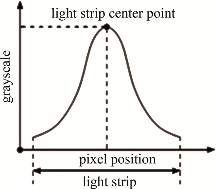
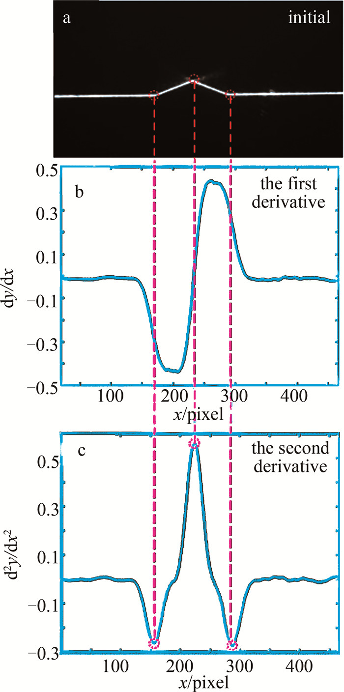
Abstract:In the seam tracking based on structured light vision, strong noise such as arc and spatter generated in the welding process would greatly reduce the visibility of the weld, resulting in tracking failure. In order to solve this problem, a seam tracking algorithm based on the improved kernel correlation filter was proposed to better adapt to the strong noise environment. Firstly, the initial feature points of the weld were obtained. Based on the gray distribution characteristics of the weld laser stripe, the centerline of the weld laser stripe was extracted by Steger algorithm. Then the center line was filtered and derived to obtain the initial feature points of the weld. Finally, the initial feature points of the weld were used as the initial input, and the improved kernel correlation filter was applied to learn and track the weld feature points. The results show that, the average error of the algorithm is 0.305 mm, and the maximum tracking error is 0.479 mm in the case of strong noise interference, which achieves good tracking effect and effectively avoids tracking drift. This study provides a useful reference for high-precision seam tracking.
-
0. 引言
光波在大气中传输时,因大气湍流的存在,会对光波产生光斑的扩展、光强闪烁和光束的传播方向发生偏折等一系列现象[1-3],从而限制了光电设备的性能。光波受湍流的影响主要是温度起伏引起的[4],温度起伏引起折射率的起伏,造成光束波前的畸变。通过对温度起伏的直接测量,可以计算出大气折射率结构常数Cn2[5-6]。测量温度起伏的仪器为温度脉动仪[7-8],通常利用10 μm左右的金属丝来测量单点的大气湍流强度,具有响应快速、线性度好、分辨率高等特点。将温度脉动仪放置在近地面的光电设备附近,可以测量近地面的Cn2[9-12]; 通过搭载温度脉动仪的测量塔,可以测量表面层的湍流强度随高度分布情况;将温度脉动仪搭载到探空气球上,可以测量光学站址的大气Cn2廓线[13-14]。
折射率结构常数Cn2作为一个随机量,其测量值的不确定度对于准确测量外场湍流强度、评估光电设备的性能具有重要意义。本文作者从温度脉动仪的测量原理出发,结合测量不确定度的定义,分析了影响温度脉动仪测量结果的各个因素,并定量计算了温度脉动仪的测量不确定度。
1. 温度脉动仪测量原理
1.1 测量原理
大气湍流强度的表征参数Cn2由科尔莫戈罗夫提出[15],对局部均匀和各向同性的涡流,用折射率结构函数Dn(r)来表征折射率的变化,它与测量距离r存在正比关系,与r的2/3次方成正比:
Dn(r)=⟨[n(r1+r)−n(r1)]2⟩=C2n(h)×r2/3,(l≪r≪L) (1) 式中:l为湍流内尺寸; L为湍流外尺寸; n(r1)为r1处的折射率; n(r1+r)为r1+r处的折射率; Dn(r)是根据2个观测点间折射率增量,先计算均方值再统计平均值得到; Cn2(h)为h处的比例常数,是大气湍流强度的表示方式,表示h处的平均湍流强度,量纲为m-2/3,称为折射率结构常数。
折射率的变化是由于温度起伏而产生的,在湍流的惯性区间内,2个观测点的温度结构函数DT(r)只与2个观测点间的距离r2/3有关,与2个观测点的相对方向和位置没有关系[3]。如果大气中2个观测点之间的距离在湍流惯性区的范围内,则会满足以下表达式:
DT(r)=C2T(h)×r2/3,(l≪r≪L) (2) 式中:CT2(h)是温度结构常数,单位为K2·m-2/3; r的单位是m。
空间两点的温度结构函数为:
DT(r)=⟨[T(x)−T(x+r)]2⟩ (3) 式中: T(x)和T(x+r)分别为空间中两个不同位置点的温度; 〈[T(x)-T(x+r)]2〉表示空间中两个点温度差的系综平均。
由上面的两个式子可以得出大气的温度结构函数为:
C2T(r)=⟨[T(x)−T(x+r)]2⟩×r−2/3 (4) 在光学波段,Cn2和CT2的关系[10]可以描述为:
C2n=(79.2×10⁻⁶×pT2)2×C2T (5) 式中: p是空间测量点的气压(单位为Pa); T是绝对温度(单位为K)。温度脉动仪通过测量距离r、温度T、气压p和温差的系综平均值等数值,可以算出折射率结构常数。测量温度差系综平均值[16-17]的是金属丝传感器[18],如铂丝、钨丝等。金属丝传感器的电阻值随温度变化呈线性变化。通过测量金属丝电阻值的变化,就可以推导出温度的变化。金属丝传感器的热惯性系数小,能够响应大气温度的微小和快速变化。
1.2 测量电路设计
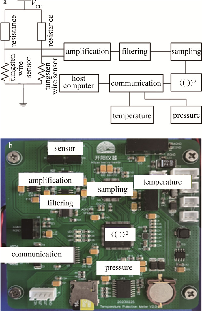
温度脉动仪的电路示意图[19]如图 1a所示。利用惠斯通电桥,经过仪表放大器、滤波、采样和计算,测量距离为r的空间两点的金属丝传感器温度差的系综平均,同时测量压强和气温,就可由前面的公式计算大气折射率结构常数。图 1b为电路实物图。
![图 1 a—温度脉动仪的电路示意图b—电路实物图]() 图 1 a—温度脉动仪的电路示意图b—电路实物图Figure 1. a—circuit diagram of temperature pulsation meter b—circuit diagram
图 1 a—温度脉动仪的电路示意图b—电路实物图Figure 1. a—circuit diagram of temperature pulsation meter b—circuit diagram2. 温度脉动仪测量不确定度分析
测量不确定度是依照所得到的数据信息,用来表征赋予被测量的量值分散性的非负参量。测量不确定度以定量的方式表示测量结果的可信度[20-22]。测量不确定度小,说明对应的特定测量获得的可能量值分布范围小,因而可信程度高,使用价值高。标准不确定度[23]通过用标准偏差的测量结果的不确定度来定义。就温度脉动仪而言,Cn2作为被测量的量,是一个随机量,因此无法通过独立重复测量的方法来估计测量不确定度,只能通过对影响Cn2的各输入量进行估计,得到合成标准不确定度。
根据式(4),影响Cn2的输入量有压强p、距离r、温度T和两点间温度差的系综平均, 则:
U(Cn2)=√U2(p)+U2(T)+U2(r)+U2(⟨[T(x)−T(x+r)]2⟩) (6) 式中: U(p)表示压强引入的不确定度,是由压强传感器的测量不确定度给出; U(T)表示温度引入的不确定度,由温度传感器的测量不确定度给出; U(CT2)表示温度结构常数的不确定度,由温度脉动的测量不确定度和距离r的测量不确定度给出。
对于压强、温度和距离r,选用合适的传感器和测量工具,各输入变量的不确定度分别为:
U(p)=±1 Pa (7) U(T)=±0.3 K (8) U(r)=±0.01 m (9) 在近地面一般测量条件下,压强p=105 Pa,距离r=1 m,温度T=20 ℃(293 K),不同的温度起伏对应的折射率结构常数见表 1。
表 1 近地面条件下不同温度起伏对应的折射率结构常数Table 1. Refractive index structure constants corresponding to different temperature fluctuations under near ground conditionsCn2/m-2/3 p/Pa T/K r/m 〈[T(x)-T(x+r)]2〉 8.5×10⁻¹⁹ 1×10⁵ 293 1 10-6 8.5×10⁻¹⁸ 1×10⁵ 293 1 10-5 8.5×10⁻¹⁷ 1×10⁵ 293 1 10-4 8.5×10⁻¹⁶ 1×10⁵ 293 1 10-3 8.5×10⁻¹⁵ 1×10⁵ 293 1 10-2 8.5×10⁻¹⁴ 1×10⁵ 293 1 10-1 8.5×10⁻¹³ 1×10⁵ 293 1 100 8.5×10⁻¹² 1×10⁵ 293 1 101 8.5×10⁻¹¹ 1×10⁵ 293 1 102 两点温度差的系综平均值由被测量大气温度起伏和噪声共同决定。其中噪声因素包括金属丝传感器及其支架的热惯性、滤波电路的影响、采样电路中的噪声、金属丝中电流的加热效应、太阳直射对金属丝传感器的加热等[24]。金属丝及其支架的惯性对高频湍流有响应衰减,金属丝中电流的加热效应和太阳直射的加热是一个稳定量,可以通过电路的高通滤波过滤去除。滤波电路的影响对电路频率的影响可通过校正系数去除。采样电路中的噪声为选用芯片的噪声决定。
采用钨丝传感器,直径为10 μm,钨丝的温度变化系数为4.5×10⁻³/K, 电阻值为90 Ω。表 2中给出了两点之间不同的温度起伏,对应的电阻值变化和压强变化。
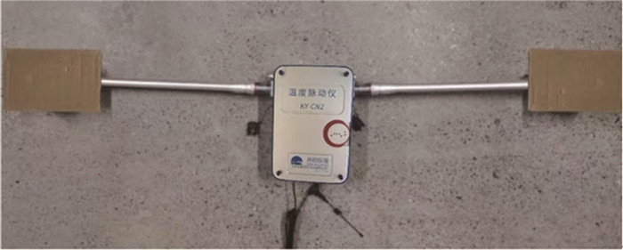
表 2 温度起伏对应的电阻值和电压变化Table 2. Changes of resistance and voltage corresponding to temperature fluctuations[T(x)-T(x+r)]/K resistance change value/Ω current value/mA voltage change value/mV 10-3 0.000405 1 0.000405 10-2 0.00405 1 0.00405 10-1 0.0405 1 0.0405 100 0.405 1 0.405 101 4.05 1 4.05 将钨丝传感器放置在密封环境中,作为没有温度变化情况,测量得到电路噪声,如图 2所示。经多次重复测量,电路电压起伏可以控制在0.00025 mV以下,对应的温度起伏为0.0003 K。图 3为一次典型的噪声测量结果,因此0.0003 K可以作为温度起伏的测量不确定度。
U(T(x)−T(x+r))=±0.0003 K (10) ![图 2 放置于封闭的纸箱内的温度脉动仪钨丝传感器]() 图 2 放置于封闭的纸箱内的温度脉动仪钨丝传感器Figure 2. Tungsten wire sensor of temperature pulsation meter in the closed cardboard box
图 2 放置于封闭的纸箱内的温度脉动仪钨丝传感器Figure 2. Tungsten wire sensor of temperature pulsation meter in the closed cardboard box利式(5)对各参量求偏微分,可以得到各参量的不确定度引起的折射率结构常数的不确定度,如表 3所示。此时, p=105 Pa,T=293 K,r=1 m,温度起伏分别为10-3 K~100 K。可以看出,折射率结构常数的测量不确定度主要由电路的噪声决定。当温度起伏在10-3 K时,电路噪声几乎和温度起伏引起的电压起伏相当,此时相对不确定度可以达到60%。随着湍流强度的增强,相对不确定度也在逐步降低。
表 3 影响温度脉动仪测量不确定度的各参量对折射率结构常数不确定度的影响Table 3. Uncertainty of refractive index structure constant caused by various parameters affecting the measurement uncertainty of temperature pulsation meter[T(x)-T(x+r)]/K U(p) U(T) U(r) U(T(x)-T(x+r)) Cn2/m-2/3 U(Cn2) relative uncertainty/% 10-3 1.7×10⁻²³ 3.5×10⁻²¹ 5.7×10⁻²¹ 5.1×10⁻¹⁹ 8.5×10⁻¹⁹ 5.1×10⁻¹⁹ 60.0 10-2 1.7×10⁻¹⁹ 3.5×10⁻¹⁹ 5.7×10⁻¹⁹ 5.1×10⁻¹⁸ 8.5×10⁻¹⁷ 5.1×10⁻¹⁸ 6.0 10-1 1.7×10⁻¹⁷ 3.5×10⁻¹⁷ 5.7×10⁻¹⁷ 5.1×10⁻¹⁷ 8.5×10⁻¹⁵ 8.4×10⁻¹⁷ 1.0 100 1.7×10⁻¹⁵ 3.5×10⁻¹⁵ 5.7×10⁻¹⁵ 5.1×10⁻¹⁶ 8.5×10⁻¹³ 6.7×10⁻¹⁵ 0.8 101 1.7×10⁻¹³ 3.5×10⁻¹³ 5.7×10⁻¹³ 5.1×10⁻¹⁵ 8.5×10⁻¹¹ 6.7×10⁻¹⁴ 0.8 3. 结论
从温度脉动仪的测量原理出发,结合测量不确定度的定义,分析了影响温度脉动仪测量结果的各个因素,并定量计算了温度脉动仪的测量不确定度。研究表明,近地面层的大气折射率结构常数的范围通常在10-13 m-2/3~10-16 m-2/3之间[25],此时温度脉动仪的测量不确定小于1%,有比较高的可信度。该研究对于提高温度脉动仪的测量分辨率有一定效果,同时也为控制其测量不确定度提供了新的解决途径。
-
![]()
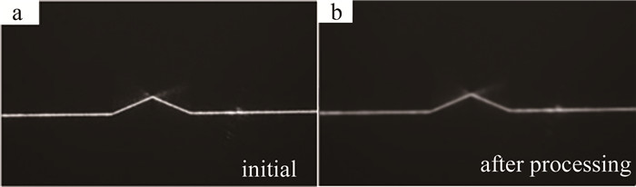
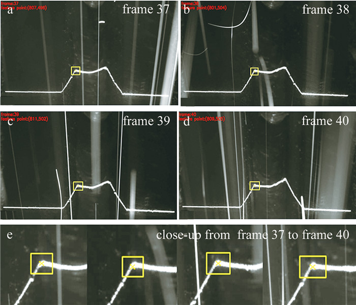
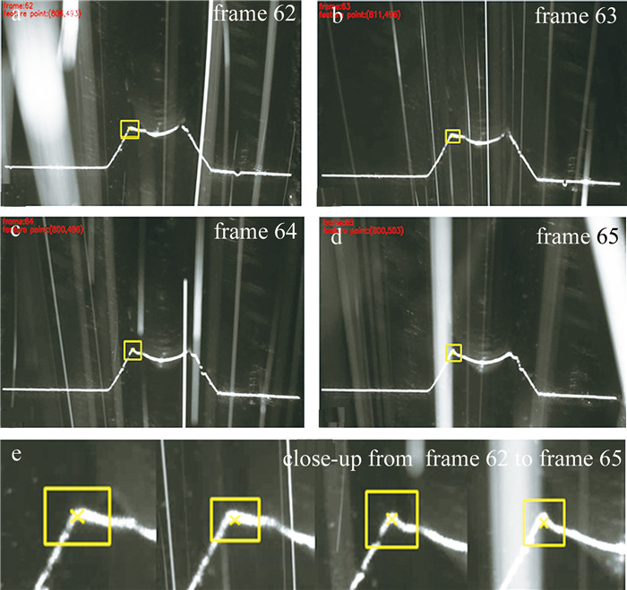
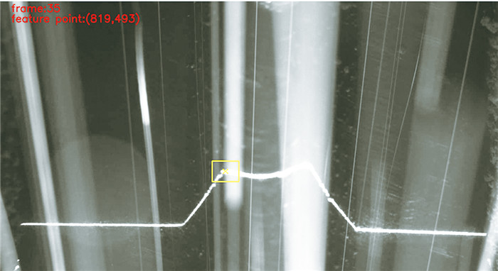
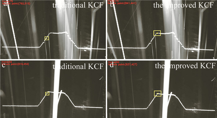
图 13 改进KCF算法下跟踪漂移的修正
Figure 13. Tracking drift correction under the improved KCF algorithm
表 1 特征点跟踪误差
Table 1 Tracking errors of feature points
group number of welding average/mm maximum/mm RMS/mm 1 0.279 0.421 0.311 2 0.312 0.476 0.342 3 0.286 0.378 0.327 4 0.341 0.479 0.374  下载: 导出CSV
-
[1] ROUT A, DEEPAK B, BISWAL B B. Advances in weld seam tracking techniques for robotic welding: A review[J]. Robotics and Computer-Integrated Manufacturing, 2019, 56: 12-37. DOI: 10.1016/j.rcim.2018.08.003
[2] XU Y, FANG G, LV N, et al. Computer vision technology for seam tracking in robotic GTAW and GMAW[J]. Robotics and Computer-Integrated Manufacturing, 2015, 32: 25-36. DOI: 10.1016/j.rcim.2014.09.002
[3] DINHAM M, FANG G. Autonomous weld seam identification and localisation using eye-in-hand stereo vision for robotic arc welding[J]. Robotics and Computer-Integrated Manufacturing, 2013, 29: 288-301. DOI: 10.1016/j.rcim.2013.01.004
[4] LIU J, FAN Z, OLSEN S I, et al. Boosting active contours for weld pool visual tracking in automatic arc welding[J]. IEEE Transactions on Automation Science and Engineering, 2015, 14(2): 1096-1108.
[5] XU Y, LV N, FANG G, et al. Welding seam tracking in robotic gas metal arc welding[J]. Journal of Materials Processing Technology, 2017, 248: 18-30. DOI: 10.1016/j.jmatprotec.2017.04.025
[6] BANAFIAN N, FESHARAKIFARD R, MENHAJ M B. Precise seam tracking in robotic welding by an improved image processing approach[J]. The International Journal of Advanced Manufacturing Technology, 2021, 114: 251-270. DOI: 10.1007/s00170-021-06782-4
[7] XIA L, ZHOU J, XUE R, et al. Real-time seam tracking during narrow gap GMAW process based on the wide dynamic vision sensing method[J]. Journal of Manufacturing Processes, 2023, 101: 820-834. DOI: 10.1016/j.jmapro.2023.06.045
[8] ZHANG Z, MALASHKHIA L, ZHANG Y, et al. Design of Gaussian process based model predictive control for seam tracking in a laser welding digital twin environment[J]. Journal of Manufacturing Processes, 2022, 80: 816-828. DOI: 10.1016/j.jmapro.2022.06.047
[9] ZOU Y, ZHU M, CHEN X. A robust detector for automated welding seam tracking system[J]. Journal of Dynamic Systems, Measurement, and Control, 2021, 143(7): 071001. DOI: 10.1115/1.4049547
[10] ZHAO Z, LUO J, WANG Y, et al. Additive seam tracking technology based on laser vision[J]. The International Journal of Advanced Manufacturing Technology, 2021, 116: 197-211. DOI: 10.1007/s00170-021-07380-0
[11] DU R Q, XU Y L, HOU Zh, et al. Strong noise image processing for vision-based seam tracking in robotic gas metal arc welding[J]. The International Journal of Advanced Manufacturing Technology, 2019, 101: 2135-2149. DOI: 10.1007/s00170-018-3115-2
[12] WANG N, ZHONG K, SHI X, et al. A robust weld seam recognition method under heavy noise based on structured-light vision[J]. Robotics and Computer-Integrated Manufacturing, 2020, 61: 101821. DOI: 10.1016/j.rcim.2019.101821
[13] LI J, LI B, DONG L, et al. Weld seam identification and tracking of inspection robot based on deep learning network[J]. Drones, 2022, 6(8): 216. DOI: 10.3390/drones6080216
[14] GU W P, XIONG Z Y, WAN W. Autonomous seam acquisition and tracking system for multi-pass welding based on vision sensor[J]. The International Journal of Advanced Manufacturing Technology, 2013, 69: 451-460. DOI: 10.1007/s00170-013-5034-6
[15] XU Y L, FANG G, CHEN Sh B, et al. Real-time image processing for vision-based weld seam tracking in robotic GMAW[J]. The International Journal of Advanced Manufacturing Technology, 2014, 73: 1413-1425. DOI: 10.1007/s00170-014-5925-1
[16] 李小刚, 富巍. 基于激光测距的机器人焊缝跟踪研究[J]. 装备制造技术, 2018(6): 161-165. LI X G, FU W. Research on robot welding seam tracking based on laser ranging[J]. Equipment Manufacturing Technology, 2018(6): 161-165(in Chinese).
[17] STEGER C. An unbiased detector of curvilinear structures[J]. IEEE Transactions on Pattern Analysis and Machine Intelligence, 1998, 20(2): 113-125. DOI: 10.1109/34.659930
[18] SHAH H N M, SULAIMAN M, SHUKOR A Z, et al. Butt welding joints recognition and location identification by using local thresholding[J]. Robotics and Computer-Integrated Manufacturing, 2018, 51: 181-188. DOI: 10.1016/j.rcim.2017.12.007
[19] 曹学鹏, 张弓, 杨根, 等. 面向三维复杂焊缝的焊接机器人焊缝跟踪方法[J]. 工程科学学报, 2023, 45(2): 310-317. CAO X P, ZHANG G, YANG G, et al. Welding seam tracking method of welding robot oriented to three-dimensional complex welding seam[J]. Chinese Journal of Engineering, 2023, 45(2): 310-317(in Chinese).
[20] HENRIQUES J F, CASEIRO R, MARTINS P, et al. High-speed tracking with kernelized correlation filters[J]. IEEE Transactions on Pattern Analysis and Machine Intelligence, 2014, 37(3): 583-596.
[21] KNYAZ V A, ZHELTOV S Y, VISHNYAKOV B V. Robust object tracking techniques for vision-based 3D motion analysis applications[J]. Proceedings of the SPIE, 2016, 9896: 334-342.
[22] ZHOU Y, YANG W, SHEN Y. Scale-adaptive KCF mixed with deep feature for pedestrian tracking[J]. Electronics, 2021, 10(5): 536. DOI: 10.3390/electronics10050536
[23] 吴家洲, 刘君, 施佳文, 等. 激光焊缝图像分割与颜色识别方法研究[J]. 激光技术, 2023, 47(5): 723-728. DOI: 10.7510/jgjs.issn.1001-3806.2023.05.022 WU J Zh, LIU J, SHI J W, et al. Research on image segmentation and color recognition method of laser weld[J]. Laser Technology, 2023, 47(5): 723-728(in Chinese). DOI: 10.7510/jgjs.issn.1001-3806.2023.05.022
[24] FEI Y, GAO G, WU D, et al. Improved KCF algorithm and its application to target lost prediction[C]//2022 4th International Conference on Intelligent Control, Measurement and Signal Processing (ICMSP). New York, USA: IEEE Press, 2022: 996-1000.

计量
- 文章访问数: 2
- HTML全文浏览量: 0
- PDF下载量: 4