Measurement method for surface topography based on quadriwave lateral shearing interferometry
-
摘要: 为了解决传统四波横向剪切干涉测量系统中特定分光器件存在的加工难度高、光谱适用范围受限等问题,利用空间光调制器替代分光光栅将入射光分为4束横向剪切相干子波,通过灵活调整光栅的折射率来调制子波衍射效率以适应照明光源,再根据子波两两干涉效应重建出反映样品折射率和高度信息的光程差分布,即可实现宽光谱大尺寸范围内的表面形貌精确测量;结合傅里叶变换法研究了入射光不同波长对光程差重建精度的影响规律,并利用空间光调制器搭建了1套适用于可见光至近红外的宽光谱四波横向剪切干涉测量系统。结果表明,该系统对石英标准样件刻蚀深度的测量结果为209.39 nm±1.72 nm,与其标称值210.83 nm±2.39 nm和白光干涉仪测量值212.92 nm±1.35 nm基本保持一致,验证了所提表面形貌测量方法的有效性。该研究可为四波横向剪切干涉技术在表面形貌测量领域的扩展应用提供理论参考。Abstract: In order to solve the problems of high processing difficulty and limited spectral application range of specific spectra device in traditional quadriwave lateral shearing interferometry system, dividing incident light beam into four beams of lateral shearing coherent wavelets was proposed by using a spatial light modulator instead of a spectro grating. The diffraction efficiency of wavelets was adjusted flexibly by adjusting the refractive index of grating to adapt to the illumination light source, and the optical path difference distribution reflecting the height information and refractive index of the sample was reconstructed according to the interference effect between two wavelets, so as to realize accurate measurement of surface topography in a wide spectral and large dimensions range. In this study, the effect of incident light wavelength on the reconstruction accuracy of optical path difference was investigated by combining the Fourier transform method, and a wide spectrum quadriwave lateral shearing interferometry system from the visible to near infrared was built using a spatial light modulator. The results show that the system measured the etching depth of a standard quartz sample at 209.39 nm±1.72 nm, which is basically consistent with its nominal value of 210.83 nm±2.39 nm and the measurement value of 212.92 nm±1.35 nm by white light interferometer, which verifies the effectiveness of the surface topography measurement method proposed. This study can provide a theoretical reference for the extended application of quadriwave lateral shearing interferometry in the field of surface topography measurement.
-
-
表 1 本文中方法与白光干涉法测得石英样品的刻蚀深度和相对误差
Table 1 Etching depth and relative error of quartz sample measured by the method of this paper and white light interferometry
method type h/nm relative error/% measuring time/s nominal values 210.83±2.39 — — white light interferometry 212.92±1.35 0.99 23.53 proposed method 209.39±1.72 0.68 < 1 表 2 本文中方法与白光干涉法测得硅晶圆样品的高度和相对误差
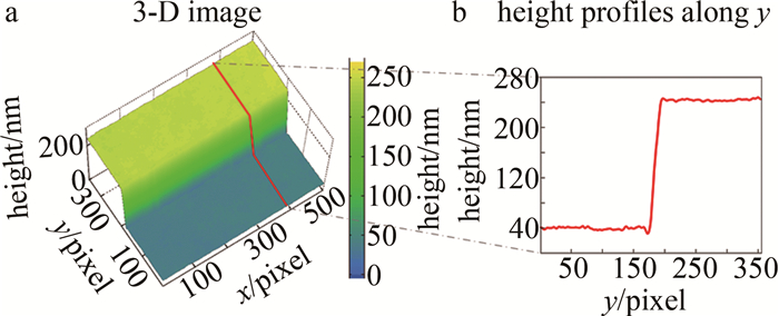
Table 2 Height and relative error of silicon wafer sample measured by the method of this paper and white light interferometry
method type h/nm relative error/% measuring time/s nominal values 200 — — white light interferometry 201.63±1.05 0.82 21.63 proposed method 201.95±1.19 0.98 < 1 -
[1] 刘佳敏, 赵杭, 吴启哲, 等. 先进节点图案化晶圆缺陷检测技术[J]. 激光与光电子学进展, 2023, 60(3): 0312003. LIU J M, ZHAO H, WU Q Zh, et al. Patterned wafer defect inspection at advanced technology nodes[J]. Laser & Optoelectronics Progress, 2023, 60(3): 0312003(in Chinese).
[2] 金川. 基于数字全息的微纳结构测量及其关键技术研究[D]. 北京: 中国科学院大学, 2022. JIN Ch. Research on micro-nano structure measurement based on digital holography and its key technologies[D]. Beijing: Graduate University of the Chinese Academy of Sciences, 2022(in Chinese).
[3] 韩志国, 李锁印, 冯亚南, 等. 接触式轮廓仪探针状态检查图形样块的研制[J]. 微纳电子技术, 2019, 56(9): 761-765. HAN Zh G, LI S Y, FENG Y N, et al. Development of the inspection pattern specimen for the contact profiler stylus state[J]. Micronanoelectronic Technology, 2019, 56(9): 761-765(in Chinese).
[4] HUI F, LANZA M. Scanning probe microscopy for advanced nanoelectronics[J]. Nature Electronics, 2019, 2(6): 221-229. DOI: 10.1038/s41928-019-0264-8
[5] CHEN J L, YU Q H, GE B, et al. A phase difference measurement method for integrated optical interferometric imagers[J]. Remote Sensing, 2023, 15(8): 2194. DOI: 10.3390/rs15082194
[6] YUAN X, XUE Y G, MIN J W, et al. High-precision gaseous flame temperature field measurement based on quadriwave-lateral shearing interferometry[J]. Optics and Lasers in Engineering, 2023, 162: 10730.
[7] KHADIR S, ANDRÉN D, VERRE R, et al. Metasurface optical characterization using quadriwave lateral shearing interferometry[J]. ACS Photonics, 2021, 8(2): 603-613. DOI: 10.1021/acsphotonics.0c01707
[8] 刘克, 张孝天, 钟慧, 等. 四波前横向剪切干涉仪的关键技术研究[J]. 光学学报, 2023, 45(15): 1512001. LIU K, ZHANG X T, ZHONG H, et al. Key technologies of quadri-Wave lateral shearing interferometer[J]. Acta Optica Sinica, 2023, 43(15): 1512001(in Chinese).
[9] 位文广, 韩俊鹤, 付玉洲. 一种两步相移数字全息的设计与实验验证[J]. 激光技术, 2020, 44(1): 86-90. DOI: 10.7510/jgjs.issn.1001-3806.2020.01.015 WEI W G, HAN J H, FU Y Zh. Design and verification of two-step phase-shifted digital holography[J]. Laser Technology, 2020, 44(1): 86-90(in Chinese). DOI: 10.7510/jgjs.issn.1001-3806.2020.01.015
[10] ZHONG Zh, WANG Ch, LIU L, et al. Diffraction phase microscopy using a defocus grating[J]. Journal of Modern Optics, 2022, 69(4): 219-224. DOI: 10.1080/09500340.2021.2024289
[11] 朱文华. 多波段激光波前瞬态干涉关键技术研究[D]. 南京: 南京理工大学, 2019. ZHU W H. Research on transient interferometric techniques of laser wavefront at multiple wavelengths[D]. Nanjing: Nanjing University of Science and Technology, 2019(in Chinese).
[12] 崔博川. 基于衍射光学元件的多波前横向剪切干涉方法研究[D]. 北京: 中国科学院大学, 2018. CUI B Ch. Research on multiwave lateral shearing interferometry based on diffractive optical elements[D]. Beijing: Graduate University of the Chinese Academy of Sciences, 2018(in Chinese).
[13] DAI F, TANG F, WANG X, et al. Generalized zonal wavefront reconstruction for high spatial resolution in lateral shearing interferometry[J]. Journal of the Optical Society of America, 2012, A29(9): 2038-2047.
[14] LI J, TANG F, WANG X Zh, et al. Wavefront reconstruction for lateral shearing interferometry based on difference polynomial fitting[J]. Journal of Optics, 2015, 17(6): 065401. DOI: 10.1088/2040-8978/17/6/065401
[15] PRIMOT J, GUéRINEAU N. Extended hartmann test based on the pseudoguiding property of a hartmann mask completed by a phase chessboard[J]. Applied Optics, 2000, 39(31): 5715-5720. DOI: 10.1364/AO.39.005715
[16] LING T, LIU D, YUE X M, et al. Quadriwave lateral shearing interferometer based on a randomly encoded hybrid grating[J]. Optics Letters, 2015, 40(10): 2245-2248. DOI: 10.1364/OL.40.002245
[17] 方波. 基于位相光栅的四波横向剪切干涉法波前检测技术研究[D]. 南京: 南京理工大学, 2014. FANG B. Wavefront measurement with four-wave lateral shearing interferometry based on phase grating[D]. Nanjing: Nanjing University of Science and Technology, 2014(in Chinese).
[18] 宋金伟, 闵俊伟, 袁勋, 等. 基于二维朗奇相位光栅的四波横向剪切干涉定量相位成像[J]. 光子学报, 2022, 51(11): 1118001. SONG J W, MIN J W, YUAN X, et al. Quadriwave lateral shearing interferometry quantitative phase imaging based on 2D ronchi phase grating[J]. Acta Photonica Sinica, 2022, 51(11): 1118001(in Chinese).
[19] ZHAO Z X, ZHUANG Y Y, XIAO Zh X, et al. Characterizing a liquid crystal spatial light modulator at oblique incidence angles using the self-interference method[J]. Chinese Optics Letters, 2018, 16(9): 090701.
[20] KOTTLER C, DAVID C, PFEIFFER F, et al. A two-directional approach for grating based differential phase contrast imaging using hard X-rays[J]. Optics Express, 2007, 15(3): 1175-1181.
[21] 翟中生, 黄缘胜, 李沁洋, 等. 基于空间光调制器的正交相位光栅衍射特性[J]. 光学学报, 2022, 42(16): 1605002. ZHAI Zh Sh, HUANG Y Sh, LI Q Y, et al. Diffraction characteristics of orthogonal phase grating based on spatial light modulator[J]. Acta Optica Sinica, 2022, 42(16): 1605002(in Chinese).
[22] BAFFOU G. Quantitative phase microscopy using quadriwave lateral shearing interferometry (QLSI): Principle, terminology, algorithm and grating shadow description[J]. Journal of Physics, 2021, D54(29): 294002.


 下载:
下载:

