Research of alignment method for polarization maintaining fiber based on double beam light source
-
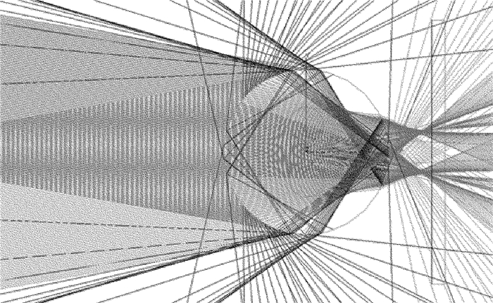
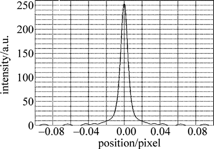
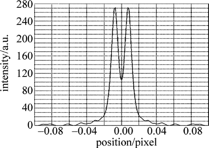
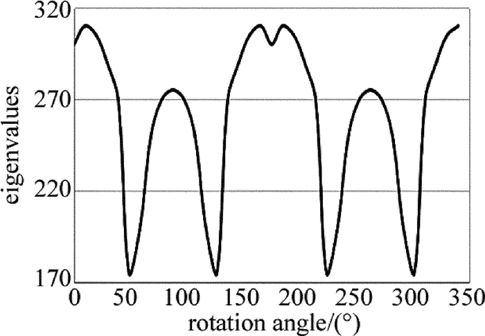
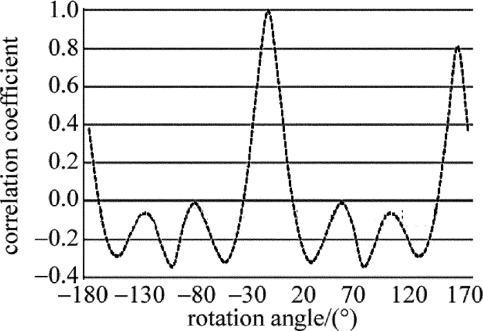
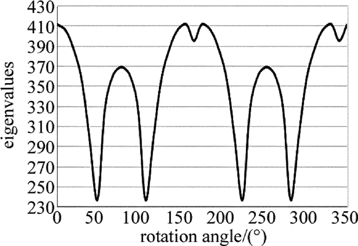
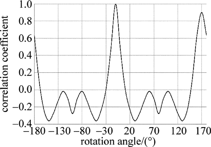
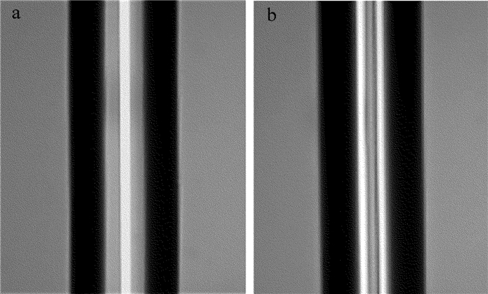
摘要: 现有保偏光纤侧视成像法多依赖于某特定形貌光强分布,对成像面位置调整要求高、通用性差。为了提高保偏光纤定轴灵敏度、增加方法的通用性、提高定轴稳定性,采用双光束光源取代单光束光源对保偏光纤进行侧视成像的方法,改变了以往通过调整成像面寻找特定形貌光强分布的思路,并进行了理论分析、仿真模拟和实验验证。结果表明,采用双光束光源进行侧视成像时,光强分布成双峰型,选择双峰光强值之和为特征值,建立特征值与偏转角度的对应关系,利用互相关分析可对偏转角进行确定,该方法不仅保持了透镜效应侧视法适用成像面范围广的优点,而且定轴灵敏度平均优于单光束光源侧视成像定轴法11.88%。该研究具有良好的实用前景。Abstract: The current side-view imaging alignment method for polarization-maintaining fiber depended on the specific light intensity distribution, and had strict requirements on the position adjustment of the imaging plane. In order to improve the sensitivity of the fixed axis, increase the universality of the method and improve the stability of the fixed axis, a double-beam light source was used to replace the single-beam light source for the side-view imaging of the polarization maintaining fiber. The idea of finding the intensity distribution of the specific morphology by adjusting the image plane was changed. After theoretical analysis, simulation and experimental verification, the results show that, when using double-beam light source for side-view imaging, the light intensity distribution has bimodal pattern, and the sum of the bimodal light intensity values is selected as the eigenvalue to establish the corresponding relationship between the eigenvalue and the deflection angle. The deflection angle can be determined by cross-correlation analysis. This method not only maintains the advantages of wide range of imaging planes of polarization observation by the lens effect tracing(POL), but also has an axis sensitivity of 11.88% better than the single-beam side-view imaging alignment method. This method has good application prospects.
-
-
Table 1 The rotation angle when cross-correlation coefficient decreased from 1 to 0
experiment number single beam experiment double beam experiment 1 28.5° 25.1° 2 28.4° 25.0° 3 28.5° 24.9° 4 28.4° 25.1° 5 28.4° 25.2° -
[1] XIE H B, GONG R M, HAN L, et al. Optical system design of a portable laser Doppler velocimeter[J]. Laser Technology, 2011, 35(1):109-111(in Chinese). http://www.wanfangdata.com.cn/details/detail.do?_type=perio&id=jgjs201101030
[2] CHEN J J, LI L F. Investigation on the slow-light characteristics of nonlinear Bragg gratings based on optical power control[J]. Laser Technology, 2015, 39(2):224-227(in Chinese). http://www.wanfangdata.com.cn/details/detail.do?_type=perio&id=jgjs201502017
[3] ZHOU K J, ZHU J L, WEI B, et al. Research of multi-section Lyot fiber depolarizer[J]. Laser Technology, 2015, 39(6):741-744(in Chinese). http://www.wanfangdata.com.cn/details/detail.do?_type=perio&id=jgjs201506002
[4] DIAO L, WANG W L, KONG Y, et al. Influence of temperature on output polarization degree of fiber Lyot depolarizers[J]. Laser Technology, 2015, 39(2):220-223(in Chinese). http://www.wanfangdata.com.cn/details/detail.do?_type=perio&id=jgjs201502016
[5] XU H J, ZHANG Q, ZHANG Sh. Polarization dependence of polarization-maintaining fiber couplers based on intensity transmission matrix[J]. Laser Technology, 2013, 37(2):235-238(in Chinese). http://www.wanfangdata.com.cn/details/detail.do?_type=perio&id=jgjs201302024
[6] CHEN D F, LU P, LIU D M. Highly sensitive curvature sensors based on polarization-maintaining photonic crystal fibers[J]. Laser Technology, 2015, 39(4):450-452(in Chinese). http://en.cnki.com.cn/Article_en/CJFDTotal-JGJS201504004.htm
[7] XU W, JIN T, CHI H. Theoretical and experimental research of coupled optoelectronic oscillators[J]. Laser Technology, 2014, 38(5):579-585(in Chinese). http://en.cnki.com.cn/Article_en/CJFDTotal-JGJS201405001.htm
[8] WEI X Ch, OU P, ZHANG Ch X, et al. Study on single-frequency single-polarization narrow-linewidth fiber laser and its amplification[J]. Laser Technology, 2010, 34(1):5-7(in Chinese). http://www.wanfangdata.com.cn/details/detail.do?_type=perio&id=jgjs201001013
[9] OU P, XU H J, YANG D W, et al. Measurement of high-birefringent polarization-maintaining fiber and its analysis with Mueller matrix[J]. Laser Technology, 2009, 33(1):15-17(in Chinese). http://www.wanfangdata.com.cn/details/detail.do?_type=perio&id=jgjs200901032
[10] NING T G, TONG Zh, PEI L, et al. Experimental study about the modulation of fiber lasers[J]. Laser Technology, 2008, 32(1):77-79(in Chinese). http://d.old.wanfangdata.com.cn/Periodical/bdtgd201202024
[11] WANG G, LI K, KONG F M.Study of characteristics of polarization mode dispersion in single mode fibers with elliptical birefringence[J]. Laser Technology, 2006, 30(5):465-468(in Chinese). http://www.wanfangdata.com.cn/details/detail.do?_type=perio&id=jgjs200605016
[12] XU L, YAO Sh Q.Effects of temperature on the performance of twisted optic fiber loop[J]. Laser Technology, 2005, 29(1):52-55(in Chinese). http://www.wanfangdata.com.cn/details/detail.do?_type=perio&id=jgjs200501016
[13] ZHENG W. Automated fusion-splicing of polarization maintaining fibers[J].Journal of Lightwave Technology, 1997, 5(1):125-134. http://www.wanfangdata.com.cn/details/detail.do?_type=perio&id=f7aa1a788fed10b8b26604ae43f32802
[14] WANG D Y, LIU Ch, SHU X W. Accurate a-lignment of PM fiber[J].Acta Photonica Sinica, 2002, 31(3):345-348(in Chinese).
[15] WANG J E.Study on the manufacturing theory and the key techniques of fused polarization maintaining fiber couplers[D]. Changsha: National University of Defense Technology, 2007: 17-38(in Ch-inese).
[16] WANG J E, LIN Zh H, WU Y L, et al. The auto-alignment technique of PM fiber of MRI[J]. Applied Optics, 2005, 26(5):37-40. http://en.cnki.com.cn/article_en/cjfdtotal-yygx200505010.htm
[17] CHEN Sh Y.Theoretical and experimental research on azimuthal alignment method for PM-fiber based on side-viewing image[D]. Guangzhou: Ji'nan University, 2006: 37-46(in Chinese).
[18] CHEN Sh Y, DI H W, CHEN Zh, et al. Azimuthal alignment method for PM fiber based on light intensity distributions with five finger profile[J].Applied Laser, 2006, 26(1):35-38(in Chinese). http://www.wanfangdata.com.cn/details/detail.do?_type=perio&id=yyjg200601010
[19] WENG X Q, FENG D, HUANG H B, et al. Simulation of PM fibers' azimuthal alignment based on the image correlation of light intensity[J]. Acta Photonica Sinica, 2015, 44(6):0606003(in Chinese). DOI: 10.3788/gzxb
[20] LIU Zh H, FENG D, YANG D W, et al. Accurate detection technology for polarization axis of Panda polarization-maintaining fiber. Infrared and Laser Engineering, 2014, 43(10):3388-3393(in Chinese). http://www.wanfangdata.com.cn/details/detail.do?_type=perio&id=hwyjggc201410039


 下载:
下载:
