Cumulative effect of thin film laser damage under S-on-1 measurement mode
-
摘要: 为了研究薄膜激光损伤机理及影响因素,基于平顶光束辐照测量的原理,采用1064nm的Nd:YAG激光器,对电子束热蒸发方式镀制的HfO2薄膜在重复频率激光作用下损伤的累积效应进行了理论分析和实验验证。运用损伤阈值的测量原理,分析了1-on-1和S-on-1两种测量方式的特点,并分别开展了测量实验。采用二分法查找辐照激光能量,每个能量密度辐照20个测试点,应用零几率损伤阈值和最小二乘法拟合确定测量结果。结果表明,对同种薄膜,1-on-1测量方式测得的损伤阈值为15.75J/cm2,S-on-1测量方式测得的损伤阈值为11.90J/cm2;从损伤阈值与损伤形貌两方面的对比表明,S-on-1测量方式体现了典型的累积效应。此结果对深入研究薄膜激光损伤的机理和影响因素具有重要意义。Abstract: In order to study the damage mechanism and influencing factors of laser thin films, the principle of radiation measurement based on flat top beam was proposed. The cumulative damage effect of HfO2 films processed by electron beam thermal evaporation under the repeated frequency laser irradiation was studied by using 1064nm Nd:YAG laser. After theoretical analysis and experimental verification, the characteristics of two measuring methods, 1-on-1 and S-on-1, were analyzed based on the measuring principle of damage threshold. The irradiation laser energy was seeked by dichotomy. Each energy density was irradiated at 20 test points. Zero probability damage threshold and least square method were used to fit and determine the measurement results. The results show that for the same kind of film, the damage threshold measured by 1-on-1 method is 15.75J/cm2 and the damage threshold measured by S-on-1 method is 11.90J/cm2. The comparison of damage threshold and damage morphology shows that S-on-1 measurement method reflects the typical cumulative effect. The study is of great importance for the study of laser damage mechanism and influencing factors of thin film.
-
Keywords:
- thin films /
- damage threshold /
- measurement mode /
- cumulative effect /
- binary search /
- least square method
-
引言
随着激光技术的发展,激光对薄膜的损伤成为制约其向高功率、高能量发展的“瓶颈”,也成为影响高功率激光薄膜元件可靠性、稳定性和使用寿命的主要因素[1-4]。目前,国内外对薄膜损伤的研究中,大多采用中心强度高、边缘相对较弱的高斯光束辐照薄膜表面,光斑中心位置易导致薄膜的损伤,损伤部分的面积小于激光光斑面积,测量的损伤阈值比实际的阈值偏大[5-6]。从激光的角度而言,激光的波长、脉冲宽度、能量密度与功率密度、光斑面积和偏振态等都对测量结果有影响[7-9];从薄膜本身的角度而言,膜层的材料、厚度、工艺、半波覆盖层和膜层后处理等也对测量结果有影响[10-11]。
通常,薄膜激光损伤阈值与辐照的激光脉冲个数有关,脉冲个数越多损伤阈值降低[12],多脉冲激光对薄膜的损伤可以解释为热累计损伤或非线性吸收损伤。目前,国内外对激光薄膜损伤累积效应的研究均基于高斯光束辐照测量,会导致损伤阈值的测量结果偏低[13-14]。本文中基于平顶光束辐照测量,研究累积效应与作用次数的关系,采用1064nm的Nd: YAG激光束对采用电子束热蒸发方式镀制的HfO2薄膜分别进行1-on-1测量方式和S-on-1测量方式的测量实验,分析薄膜激光的损伤机理。
1. 损伤阈值测量原理
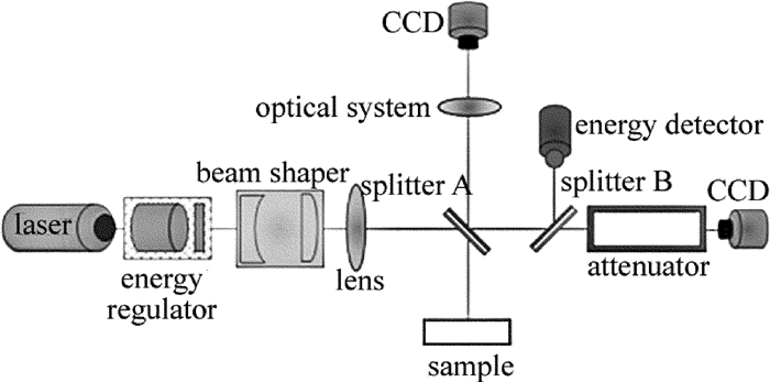
图 1为薄膜激光损伤测量原理图。激光束先通过能量调节装置,再经整形光学系统由高斯光束变换为平顶光束,然后经聚焦光学系统后被分光镜A以一定的分光比分成两部分,一部分反射到被测样品的表面,通过数码显微系统成像判识薄膜的损伤;另一部分透射到分光镜B,再按照一定的分光比将光束分成两部分,反射部分入射到能量探测器,计算出辐照到被测样品表面的激光脉冲能量,透射部分入射到CCD探测面上,计算出辐照到被测样品表面的光斑面积。根据激光脉冲能量和光斑面积计算出能量密度。应用最小二乘法对不同辐照能量密度下样品的损伤几率进行拟合,最终获得样品的激光损伤阈值。
2. 损伤阈值测量实验
2.1 测量方式
本文中对被测样品分别进行1-on-1和S-on-1两种测量方式的实验。
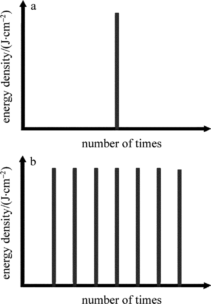
1-on-1测量又称为单脉冲损伤测量,是指同一能量密度的激光辐照在样品上的多个测试点,然后统计发生损伤的测试点个数,计算损伤几率。改变激光能量密度,再测出损伤几率,根据零几率损伤阈值获得方法求取该样品的损伤阈值[15]。采用1-on-1测量方式时,每个测试点仅辐照一次,无论是否发生损伤,都移至下一个未被辐照的测试点,如图 2a所示。
S-on-1测量又称为多脉冲损伤测量,是重复激光脉冲能量辐照在样品表面的累计损伤效应,即同一能量密度的多个脉冲辐照在同一测试点上进行测量[16-17],如图 2b所示。
2.2 1-on-1测量实验
采用不同能量密度的激光对样品进行单脉冲辐照测量,每个能量密度辐照20个间距为2mm的测试点,每个测试点仅辐照一次,通过控制样品工作台平移实现测试点的移动。采用二分法查找辐照激光能量,找到损伤几率非0%非100%的测量点,然后按照能量递增或递减的顺序进行辐照测量,应用零几率损伤阈值确定测量结果。
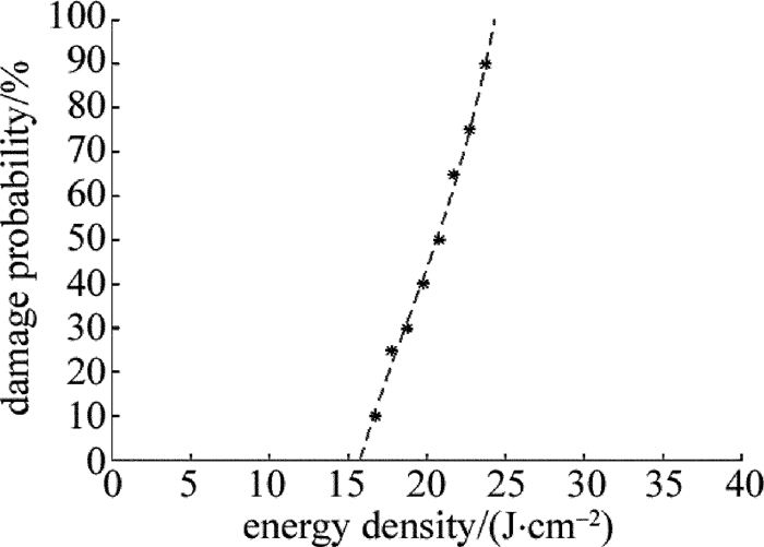
在与被测薄膜表面等效的位置测得辐照在薄膜表面的光斑直径为825μm,采用辐照激光能量密度计算软件计算得到光斑面积为5.35×10⁻³cm2,并计算出每次辐照的激光能量密度。表 1中列出了辐照的不同激光能量密度及其对应的损伤几率, *表示拟合可用数据。
Table 1. Measurement data of 1-on-1 measurement modeenergy density/(J·cm-2) damage probability/% 1 3.0 0 2 70.0 100 3 36.5 100 4* 19.75 40 5* 20.75 50 6* 21.75 65 7* 22.75 75 8* 23.75 90 9 24.75 100 10* 18.75 30 11* 17.75 25 12* 16.75 10 13 15.75 0 应用MATLAB对以上测量数据采用最小二乘法进行拟合[18],如图 3所示。拟合得到其损伤阈值为15.75J/cm2。
2.3 S-on-1测量实验
采用不同能量密度的激光对样品进行多脉冲辐照测量,每个能量密度辐照20个间距为2mm的测试点,每个测试点辐照1000次,若辐照次数未达到1000次就已判定损伤发生,则通过控制2维运动工作台的移动,对下一个测试点进行多脉冲辐照测量。采用二分法查找辐照激光能量,找到损伤几率非0%、非100%的测量点,然后按照能量递增或递减的顺序进行辐照测量,应用零几率损伤阈值确定测量结果。
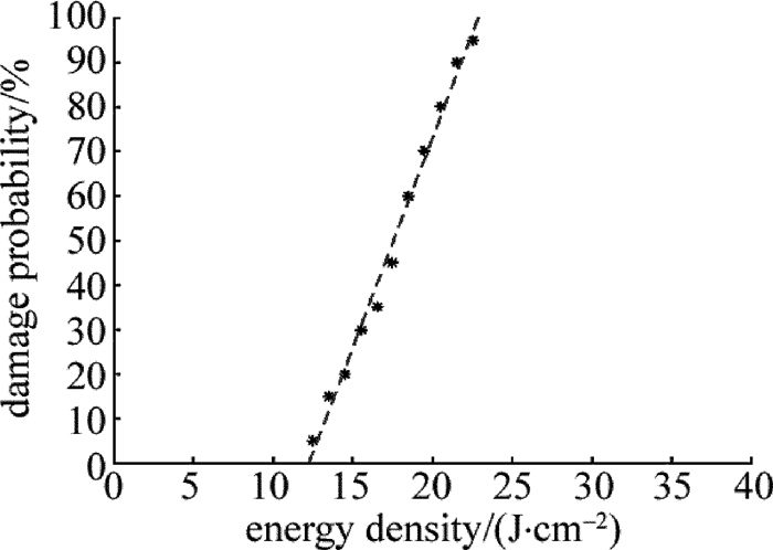
在与被测薄膜表面等效的位置测得辐照在薄膜表面的光斑直径为890μm,采用辐照激光能量密度计算软件计算得到光斑面积为6.22×10⁻³cm2,并计算出每次辐照的激光能量密度。表 2中列出了辐照的不同激光能量密度及其对应的损伤几率, *表示拟合可用数据。
Table 2. Measurement data of S-on-1 measurement modeenergy density/(J·cm-2) damage probability/% 1 3.0 0 2 42.0 100 3* 22.5 95 4* 21.5 90 5* 20.5 80 6* 19.5 70 7* 18.5 60 8* 17.5 45 9* 16.5 35 10* 15.5 30 11* 14.5 20 12* 13.5 15 13* 12.5 5 14 11.5 0 应用MATLAB对以上测量数据采用最小二乘法进行拟合,如图 4所示。拟合得到其损伤阈值为11.90J/cm2。
3. 测量实验结果对比分析
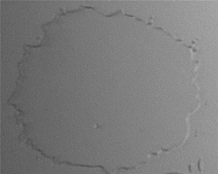
图 5中为采用1-on-1测量方式且能量密度为22.75J/cm2时的损伤形貌,由于辐照激光为平顶光束,因此膜层表面除缺陷部分外,损伤区域与光斑辐照区域基本符合。
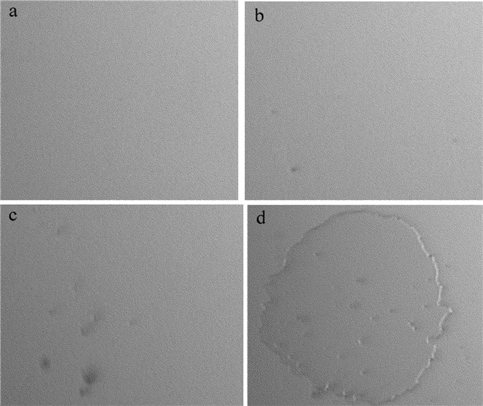
采用S-on-1测量方式能量密度为14.5J/cm2时,脉冲个数分别为1, 10, 100和1000时的损伤形貌如图 6所示。随着脉冲作用次数的增加,损伤越来越严重,尤其在缺陷存在区域首先发生损伤。
通过以上测量实验可知,采用S-on-1测量方式测得的损伤阈值比1-on-1测量方式大,S-on-1测量方式采用同一激光能量密度对同一测试点进行多脉冲辐照测量,随着脉冲次数的增加损伤越来越严重,体现了典型的累积效应。
4. 测量误差分析
系统的测量误差主要来源于激光辐照能量的测量误差、光斑面积的测量误差、测量结果的拟合误差和损伤判识误差等。
4.1 激光辐照能量测量误差
该误差主要包括:两块分光镜的分光误差为1%;能量探测器的分辨率为1μJ;平顶光束的平顶度为93.66%;薄膜表面接收激光辐照,将吸收的激光能量转化成热能,导致薄膜表面温度升高,能量探测器测量的激光能量大于薄膜实际损伤所需能量,导致测量误差的产生。
4.2 光斑面积测量误差
光斑面积的测量是在样品表面的等效位置进行的,因此CCD靶面与样品表面位置等效的偏离是误差的主要来源。为了解决这一问题,在设计聚焦光学系统时,采用长焦距结构以增大系统的焦深,使CCD靶面在一定的调节范围内测得的光斑与样品表面光斑的大小相近。焦深的表达式为:
2Δl′=λn′sin2Um′≈4λf′2n′D2 (1) 式中,λ为工作波长,f'为系统焦距,n′为像空间介质折射率,Um′为像方最大孔径角,D为系统入瞳直径。对于一定波长的激光,当入射口径一定时,焦深近似与焦距的平方成正比。
从CCD角度来说,引起光斑面积测量误差的主要因素有CCD本身的分辨率误差、CCD的积分误差以及CCD的背景噪声。
4.3 测量结果拟合误差
采用最小二乘法进行曲线拟合时会产生一定的拟合误差,同时测量时选取能量等级的多少对拟合精度产生一定影响。为了减小拟合误差,尽量多选择测量激光能量等级,尤其是损伤几率为20%~60%之间的能量对拟合结果影响最大。
5. 结论
基于平顶激光束辐照测量,采用1-on-1和S-on-1两种不同测量方式对电子束热蒸发方式镀制的HfO2薄膜激光损伤进行了研究,从损伤阈值与损伤形貌两方面验证了S-on-1测量方式体现了典型的累积效应,最后从激光辐照能量测量、光斑面积测量和测量结果拟合等方面进行了误差分析。
-
Table 1 Measurement data of 1-on-1 measurement mode
energy density/(J·cm-2) damage probability/% 1 3.0 0 2 70.0 100 3 36.5 100 4* 19.75 40 5* 20.75 50 6* 21.75 65 7* 22.75 75 8* 23.75 90 9 24.75 100 10* 18.75 30 11* 17.75 25 12* 16.75 10 13 15.75 0 Table 2 Measurement data of S-on-1 measurement mode
energy density/(J·cm-2) damage probability/% 1 3.0 0 2 42.0 100 3* 22.5 95 4* 21.5 90 5* 20.5 80 6* 19.5 70 7* 18.5 60 8* 17.5 45 9* 16.5 35 10* 15.5 30 11* 14.5 20 12* 13.5 15 13* 12.5 5 14 11.5 0 -
[1] CHANG Y H, JIN C Sh, LI Ch, et al. ArF excimer laser induced damage on high reflective fluoride film[J].Laser Technology, 2014, 38(3):302-306(in Chinese). http://www.wanfangdata.com.cn/details/detail.do?_type=perio&id=jgjs201403004
[2] HSIAO F Y, WANG T H, LEE C C, et al. Trajectory of spacecraft with photonic laser propulsion in the two-body problem[J].Acta Astronautica, 2013, 84:215-226. DOI: 10.1016/j.actaastro.2012.11.006
[3] XIA Z L, ZHAO Y A, HUANG G H, et al. Selecting energy density for laser preconditining optical films[J]. Acta Optica Sinica, 2009, 29(2):560-565(in Chinese). DOI: 10.3788/AOS
[4] KIRKWOOD S E, VANPOPTA A C, TSUI Y Y. Single and multiple shot near-infrared femtosecond laser pulse ablation thresholds of co-pper[J].Applied Physics, 2005, A81(4):729-735. DOI: 10.1007/s00339-004-3135-7
[5] FAN W X, WANG P Q, HAN J H, et al. Accumulation effect of film damage under repetitive laser pulses[J]. Laser Technology, 2014, 38(2):210-213(in Chinese). http://www.wanfangdata.com.cn/details/detail.do?_type=perio&id=jgjs201402014
[6] BECKER J, BERNHARDT A. ISO 11254:An international standard for the determination of the laser-induced damage threshold[J].Proceedings of the SPIE, 1994, 2114:703-713. DOI: 10.1117/12.180881
[7] TANG F B, XIAO J, MA Z. Study on wide spectrum characteristics of TiO2 film with ellipsometry[J]. Laser Technology, 2015, 39(6):776-779(in Chinese). http://www.wanfangdata.com.cn/details/detail.do?_type=perio&id=jgjs201506009
[8] ZHOU M, FAN Zh X, SHAO J D, et al. Thermal effects of optical film with the combined irradiation of different wavelength lasers[J]. Acta Photonica Sinica, 2009, 38(10):2608-2612(in Chinese). http://www.wanfangdata.com.cn/details/detail.do?_type=perio&id=gzxb200910033
[9] LI C, LI X, ZHANG K H, et al. Femtosecond laser induced breakdown in fused silica by linearly, circularly, and elliptically polarized lasers[J].Acta Photonica Sinica, 2014, 43(s1):153-158. http://en.cnki.com.cn/Article_en/CJFDTotal-GZXB2014S1031.htm
[10] GALLAIS L, KROL H, NATOLI J Y, et al. Laser damage resistance of silica thin films deposited by electron beam deposition, ion assisted deposition, reactive low voltage ion plating and dual ion beam sputtering[J]. Applied Optics, 2008, 515(7/8):3830-3836. http://www.wanfangdata.com.cn/details/detail.do?_type=perio&id=d9cfd57b113e112be6bd967fc23d4735
[11] LIU H, PAN F, WEI Y W, et al. Influence of defects in HfO2 film on absorptance and LIDT measurements[J]. Journal of Applied Optics, 2015, 36(2):314-320(in Chinese). DOI: 10.5768/JAO201536.0207004
[12] FU X Y, KONG M D, HU J P. The depositon of HR coating with high damage threshold for 1064nm laser[J].High Power Laser and Partice Beams, 1999, 11(4):413-417(in Chinese).
[13] WANG F, LI Y Y, CHE Y, et al. Measurement system of flattop laser induced damage threshold to film[J]. Acta Photonica Sinica, 2016, 45(3):0314003(in Chinese). DOI: 10.3788/gzxb
[14] LEI Zh, ZHANG L W, ZHANG X L, et al. Analysis and simulation of temperature field of focal plane array detector irradiated by Gaussian laser[J]. Laser Technology, 2016, 40(4):516-520(in Chin-ese). http://www.wanfangdata.com.cn/details/detail.do?_type=perio&id=jgjs201604013
[15] GUENTHER K H, HUMPHERYS T W, BALMER J, et al. 1.06microm laser damage of thin film optical coatings:a round-robin experiment involving various pulse lengths and beam diameters.[J]. Applied Optics, 1984, 23(21):3743-3752. DOI: 10.1364/AO.23.003743
[16] WANG T, ZHAO Y A, HUANG J B, et al. Accumulation effect of multi shot laser induced damage to optical coatings[J]. Acta Photonica Sinica, 2006, 35(6):859-862(in Chinese). http://www.photon.ac.cn/EN/article/showSupportInfo.do?id=12763
[17] DAI F, YANG L M. Effects of damaged appearance of coatings on its conditioning during laser conditioning[J]. Infrared and Laser Engineering, 2013, 42(1):190-194(in Chinese). http://www.wanfangdata.com.cn/details/detail.do?_type=perio&id=hwyjggc201301035
[18] BAO H, ZENG H T, BAI Y L, et al. Blade trailing edge contour based on probability density least-square fitting[J]. Laser Technology, 2016, 40(4):555-559(in Chinese). http://www.wanfangdata.com.cn/details/detail.do?_type=perio&id=jgjs201604021
-
期刊类型引用(5)
1. 王云萍,侯军燕,袁春,康文运,陈安民,张鲁薇. 飞秒激光对多光谱滤波片的损伤阈值研究. 激光技术. 2022(05): 697-701 .  本站查看
本站查看
2. 周远航,张健,冯爱新,尚大智,陈云,唐杰,杨海华. 皮秒绿激光修锐青铜基金刚石砂轮损伤规律与机制. 中国激光. 2021(06): 197-206 .  百度学术
百度学术
3. 李玉瑶,王菲,孙同同. 薄膜激光损伤阈值标定技术. 激光技术. 2021(06): 729-734 .  本站查看
本站查看
4. 付秀华,陈成,胡章贵,熊仕富,张静,王菲,王晨鑫. 278nm全固态激光系统倍频分离膜的研制. 中国激光. 2019(12): 147-155 .  百度学术
百度学术
5. 董家宁,范杰,王海珠,邹永刚,张家斌,侯春鸽. 高反射光学薄膜激光损伤研究进展. 中国光学. 2018(06): 931-948 .  百度学术
百度学术
其他类型引用(5)


 下载:
下载:
