Study on dimensional accuracy of pure copper forming parts by laser selective melting
-
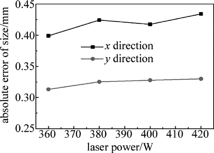
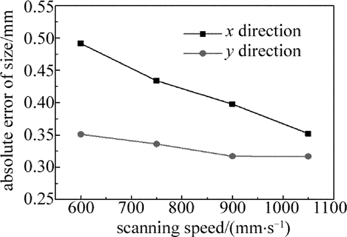
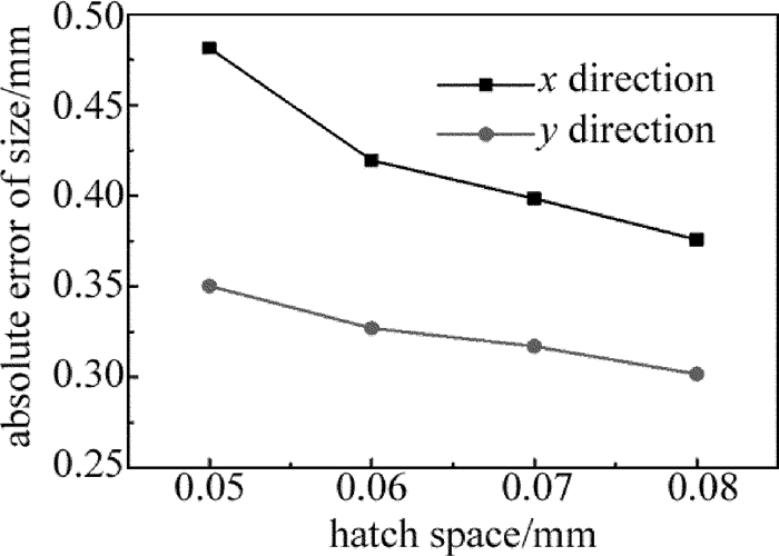
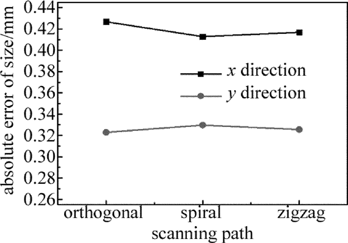
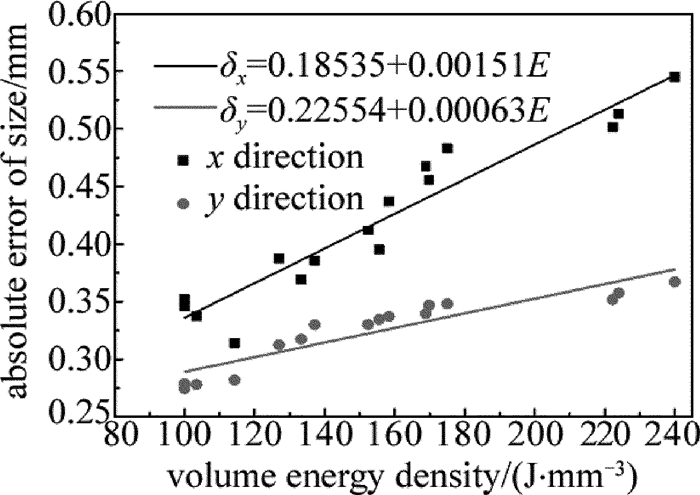
摘要: 为了研究工艺参量对激光选区熔化纯铜粉末成形件尺寸精度的影响,采用正交实验对纯铜粉末进行了激光选区熔化成形研究。分析了铺粉厚度为0.05mm时,工艺参量对成形件尺寸绝对误差的影响规律及各因素对尺寸精度的影响机理,确定了各工艺参量对尺寸绝对误差影响的主次顺序为扫描间距>扫描速率>激光功率>扫描路径,得到最优的工艺参量组合为激光功率360W,扫描速率1050mm/s,扫描间距0.08mm,扫描方式是spiral。结果表明,成形件尺寸绝对误差随激光功率的增大而增大,随扫描速率、扫描间距的增大而减小;不同扫描路径对尺寸绝对误差的影响差别较小;在因素水平范围内,尺寸绝对误差随体能量密度的增加而增大。该研究为激光烧结纯铜粉末时的参量选择提供了一定依据。Abstract: Effect of process parameters on size precision of melting copper powder forming parts by means of selective laser melting forming was studied based on orthogonal experiments. The influence of technological parameters on absolute error of forming dimension and the effect of various factors on dimensional accuracy were analyzed when the thickness of feeding powder was 0.05mm. The order of the influence of each process parameter on the absolute error of size is the scanning interval, scanning speed, laser power and scanning path. The optimum parameter combination is laser power of 360W, scanning speed of 1050mm/s, scanning interval of 0.08mm and scanning mode of spiral. The results show that, the absolute error of dimension increases with the increase of laser power and decreases with the increase of scanning speed and scanning interval. The influence of different scanning paths on the absolute error of size is small. The absolute error of size increases with the increase of bulk energy density within the range of factor. The research provides the basis for the selection of parameters in laser sintering of pure copper powder.
-
引言
我国《食品安全国家标准食品添加剂使用标准》(GB 2760-2011)[1]中明确规定了食用合成色素允许使用的种类、用量及使用范围。许多食用合成色素具有一定的毒性,过量摄入将产生致畸、致癌的风险,需严格控制使用量[2]。
目前常用的成分检测方法有高效液相色谱法[3]、示波极谱法[4-5]、薄层色谱法[6-8]、毛细管电泳法[9-10]和光谱法[11]等。光谱法具有所需的样品量较少、避免了复杂的预处理过程、分析速度快等优点,可用于实时检测中。WANG等人利用普通3维荧光光谱结合自加权交替三线性算法,对中药胡黄连和人体尿液、血液循环系统中的香草酸进行了定量分析[12],香草酸的平均回收率(样本预测浓度和实际浓度比值的平均)分别是是98.4%, 93.1%, 89.7%。MAO等人对样本的同步荧光光谱数据进行预处理,选择不同波段的光谱,结合偏最小二乘法建立了原果汁含量预测模型,得到的预测均方根误差为0.035832,相关系数为0.972570[13]。WANG等人将样本普通3维荧光光谱数据,结合误差逆向传播神经网络,测定溶液中苯并荧蒽和苯并芘的质量浓度,平均回收率分别为99.19%和99.26%[14]。
同步荧光分析法具有窄化谱带、提高选择性[15]等优点,被应用于许多分析领域中,特别是对多组分混合物的测定。对混合物质中各成分含量的测定,目前多采用2维同步荧光光谱结合神经网络的方法。2维同步荧光光谱中,激发波长与发射波长的间隔Δλ的选择很关键,直接影响光谱的形状、带宽及信号强度[15]。Δλ的值可以从理论上做预测,当其等于斯托克斯位移(激发光和荧光之间波长的移动)时,获得荧光信号最强且半峰宽度最小的单峰2维同步荧光光谱。Δλ的值最终要通过实验来确认。与2维同步荧光光谱相比,3维同步荧光光谱[16]中Δλ为一个范围,含有更多荧光光谱数据,避免了有效荧光信息的丢失。3维同步荧光光谱数据为非线性结构,径向基(radial basis function, RBF)神经网络可以任意精度逼近非线性模型,结构简单、收敛速快,是非线性拟合的理想方法之一[17-18]。本文中采用3维同步荧光光谱结合径向基神经网络的方法,测定胭脂红、日落黄混合溶液中胭脂红[19]的浓度,得到了较好的结果。
1. 原理
1.1 3维同步荧光光谱
3维同步荧光光谱为荧光强度同时随激发波长、激发波长与发射波长的间隔(即Δλ)变化的关系图谱。3维同步荧光光谱有等角3维投影图[15]和等高线光谱图两种表现形式。本文中采用等高线光谱图。
1.2 径向基神经网络
径向基神经网络属于前向神经网络类型,由MOODY和DARKEN提出。径向基神经网络分为输入层、隐含层及输出层。隐含层空间为由RBF作为隐单元的“基”构成,输入矢量在隐含层中发生变换,在低维线性不可分的数据变换到高维空间,在高维空间实现线性可分[17-18]。因此,RBF适用于非线性模型。RBF神经网络能逼近任意非线性函数,广泛应用于模式识别、时间序列分析、非线性控制等领域。
2. 实验
2.1 试剂与仪器
实验中所用仪器为FLS920P荧光光谱仪(英国Edinburgh公司)、移液器等。由国家标准物质研究中心提供胭脂红、日落黄标准色素溶液。所用水为超纯水。
配制浓度为5μg/mL胭脂红、日落黄单体色素溶液。另配制成12组不同浓度的混合色素溶液样品,其中,待测物胭脂红在2μg/mL~5.5μg/mL、干扰物日落黄在0μg/mL~2μg/mL范围内。测量样品的3维同步荧光光谱和普通3维荧光光谱。
2.2 参量设置
5μg/mL胭脂红、日落黄单体色素溶液,3维同步荧光光谱激发波长为250nm~550nm,每隔2nm激发一次;Δλ在10nm~200nm范围内,每隔2nm进行同步扫描。普通3维荧光光谱激发波长在250nm~550nm范围内,每隔2nm激发一次;发射波长在260nm~750nm范围内,每隔2nm扫描一次。混合色素溶液,3维同步荧光光谱激发波长为250nm~350nm,每隔2nm激发一次;Δλ在10nm~200nm范围内,每隔2nm进行同步扫描。普通3维荧光光谱激发波长范围为250nnm~350nm,每隔2nm激发一次;发射波长260nm~550nm,每隔2nm扫描一次。入射和出射单色狭缝仪大小均为5nm,积分时间为0.1s。
3. 计算与讨论
3.1 数据处理
为便于神经网络的应用,需对荧光光谱数据进行归一化处理。利用下式将数据归一化到0.1~0.9:
y=0.1+0.8(x−xminxmax−xmin) (1) 式中, x, xmax, xmin分别表示光谱数据、光谱数据中的最大值和最小值; y表示归一化后的数据[20]。
归一化后的数据作为RBF神经网络的输入。RBF神经网络的输出为胭脂红的浓度。实验中采用交叉验证方法中的留一交互验证法,即对于n个样本,每次剔除一个作为预测样本,其余作为训练样本。实验共预测12次,11组作为训练样本,1组预测,12组样本均被预测一次。采用留一交互验验证法,可充分利用已有的样本,减少神经网络因训练样本的输入顺序不同而产生的随机性,减小误差,提高网络的稳定性[20]。以12组样本的平均相对误差,即相对误差绝对值的平均,来判定模型的准确性。与普通3维荧光光谱数据结合RBF神经网络算法预测结果对比,验证3维同步荧光光谱结合RBF神经网络,测定混合色素溶液中胭脂红的浓度具有优越性。
3.2 实验结果
5μg/mL胭脂红、日落黄单体色素溶液,在最佳激发波长下的发射谱如图 1所示。
实验中得到胭脂红、日落黄的荧光光谱特征参量如表 1所示。
Table 1. Features of fluorescence spectrapigment effective excitation wavelength range/nm optimum excitation wavelength/
nmfluorescence emission wavelength range/
nmfluorescence peak wavelength/
nmcarmine 260~350 336 400~510 450 sunset yellow 264~308 288 380~470 418 由胭脂红、日落黄在其最佳激发波长下的发射谱及其荧光特征参量表均可以看出,胭脂红与日落黄荧光峰的位置比较接近。
图 2为5μg/mL胭脂红溶液3维同步荧光光谱等高线图及普通3维荧光光谱等高线图。
图 2a和图 2b中荧光峰的个数相同,荧光特征参量相近。3维同步荧光光谱等高线图中光谱明显发生了窄化。
2维同步荧光光谱和普通3维荧光光谱分别结合RBF神经网络,计算得到的混合溶液中待测物胭脂红的预测浓度和相对误差分别见表 2。表中第1组、第2组样本胭脂红浓度均为2.04μg/mL,干扰物日落黄浓度不等。因表格空间限制,synchronous fluorescence代表3维同步荧光光谱。
Table 2. Relative error and predicted concentration of carmine by 3-D synchronous fluorescence using RBFactual concentration/
(μg·mL-1)predicted concentration of synchronous fluorescence/
(μg·mL-1)predicted concentration of three dimensional fluorescence/
(μg·mL-1)relative error of synchronous fluorescence prediction/
%relative error of three dimensional fluorescence prediction/
%2.04 2.014 2.150 -1.28 5.37 2.04 2.049 1.655 0.45 18.88 2.72 2.613 2.687 -3.93 -1.22 3.20 3.069 3.294 -4.11 2.95 3.52 3.408 3.133 -3.18 -11.00 3.76 3.776 3.896 0.43 3.61 3.82 3.822 3.793 0.05 0.70 4.3 4.362 3.453 1.44 -19.70 4.36 4.270 4.674 -2.08 7.19 4.52 4.197 5.434 -7.16 20.22 4.80 4.832 4.534 0.67 -5.55 5.26 4.760 3.315 -9.51 -36.98 average relative error/% 2.86 11.12 由表 2可知,3维同步荧光光谱结合RBF神经网络,测定胭脂红浓度,预测的平均相对误差为2.86%。普通3维荧光光谱结合RBF神经网络,预测结果平均相对误差为11.12%,3维同步荧光光谱平均相对误差减小了8.26%。图 3中示出了3维同步荧光光谱、普通3维荧光光谱结合RBF神经网络预测胭脂红浓度结果。x轴为实际浓度,y轴为预测浓度。从图 3可以看出, 3维同步荧光光谱预测结果均匀分布在直线y=x两侧,距离较近,表明预测结果较好。普通3维荧光光谱预测结果距离直线分布较远,表明预测结果较差。
3.3 分析与讨论
(1) 同步荧光分析法能够减小光谱重叠、窄化谱带、提高分辨率,对于多组分混合物的分析常采用该分析方法。3维同步荧光光谱中Δλ为一个范围,与2维同步荧光光谱相比,有效避免了有用荧光信息的丢失。可知,对混合色素溶液中各成分含量的检测,3维同步荧光光谱更具有优势。
(2) 3维同步荧光光谱数据为非线性结构,RBF神经网络适用于非线性模型。因此,测定日落黄、胭脂红两种荧光峰相近的混合色素溶液中胭脂红的浓度,3维同步荧光光谱结合RBF神经网络结果较好。
4. 结论
通过采用3维同步荧光光谱结合RBF神经网络算法的方法,预测荧光光谱重叠严重的胭脂红、日落黄混合溶液中胭脂红的浓度,预测结果平均相对误差为2.86%。结果表明,对于混合色素溶液各色素浓度测定,3维同步荧光光谱具有优越性。
-
Table 1 Parameters of orthogonal experiment
levels factors laser power/W scanning speed/(mm·s-1) hatch space/mm scanning path 1 360 600 0.05 zigzag 2 380 750 0.06 orthogonal 3 400 900 0.07 spiral 4 420 1050 0.08 Table 2 Orthogonal experimental results
No. laserpower scanningspeed hatch space scanning path absolute error of size/mm δx δy 1 2 2 2 2 0.4673 0.3394 2 2 4 3 1 0.3374 0.2779 3 1 2 3 1 0.3856 0.3298 4 3 3 3 3 0.3875 0.3123 5 1 1 1 1 0.5449 0.3669 6 1 4 2 3 0.3141 0.2819 7 3 1 2 1 0.5015 0.3517 8 1 3 4 2 0.3520 0.2742 9 4 3 2 1 0.3952 0.3344 10 2 3 1 1 0.4559 0.3467 11 3 4 1 2 0.4118 0.3300 12 2 1 4 3 0.4368 0.3370 13 4 1 3 2 0.4831 0.3479 14 3 2 4 1 0.3692 0.3172 15 4 4 4 1 0.3456 0.2785 16 4 2 1 3 0.5133 0.3574 K1/mm x direction 1.5966 1.9663 1.9259 3.3353 y direction 1.2528 1.4035 1.4010 2.6051 K2/mm x direction 1.6974 1.7354 1.6781 1.7142 y direction 1.3010 1.3438 1.3376 1.2915 K3/mm x direction 1.6700 1.5906 1.5936 1.6517 y direction 1.3112 1.2676 1.2679 1.3188 K4/mm x direction 1.7372 1.4089 0.5036 y direction 1.3182 1.2673 1.1917 K1/mm x direction 0.3991 0.4916 0.4815 0.4169 y direction 0.3132 0.3509 0.3503 0.3256 K2/mm x direction 0.4244 0.4339 0.4195 0.4286 y direction 0.3253 0.3360 0.3269 0.3229 K3/mm x direction 0.4175 0.3977 0.3984 0.4129 y direction 0.3278 0.3169 0.3170 0.3297 K4/mm x direction 0.4343 0.3522 0.3759 y direction 0.3300 0.3168 0.3017 R/mm x direction 0.0352 0.0674 0.1056 0.0137 y direction 0.0168 0.0339 0.0486 0.0068 R′/mm x direction 0.0317 0.0607 0.0950 0.0123 y direction 0.0151 0.0305 0.0437 0.0061 Table 3 Absolute error of sizes under different energy densities
No. E/(J·mm-3) δx/mm δy/mm 1 168.89 0.4673 0.3394 2 103.40 0.3374 0.2779 3 137.14 0.3856 0.3298 4 126.98 0.3875 0.3123 5 240.00 0.5449 0.3669 6 114.28 0.3141 0.2819 7 222.22 0.5015 0.3517 8 100.00 0.3520 0.2742 9 155.56 0.3952 0.3344 10 169.78 0.4559 0.3467 11 152.38 0.4118 0.3300 12 158.33 0.4368 0.3370 13 175.00 0.4831 0.3479 14 133.33 0.3692 0.3172 15 100.00 0.3456 0.2785 16 224.00 0.5133 0.3574 -
[1] DU Y L, SUN F, YUAN G, et al. Current status of materials for three-dimensional printing[J]. Journal of Xuzhou Institute of Technology (Natural Sciences Edition), 2014, 29(1):20-24(in Chin-ese). http://en.cnki.com.cn/Article_en/CJFDTOTAL-OXZG201401004.htm
[2] LU B H, LI D C. Development of the additive manufacturing (3-D printing) technology[J]. Machine Building & Automation, 2013, 42(4):1-4(in Chinese).
[3] YANG J, LONG L U, LI Y P. Progress on the fabricating technology of EDM tool electrode[J]. Machine Tool & Hydraulics, 2007, 35(11):152-156(in Chinese). http://www.wanfangdata.com.cn/details/detail.do?_type=perio&id=jcyyy200711050
[4] ZHAO J F, MA Zh Y, XIE D Q, et al. Metal additive manufacturing technique[J]. Journal of Nanjing University of Aeronautics & Astronautics, 2014, 46(5):675-683(in Chinese). http://d.old.wanfangdata.com.cn/Periodical/njhkht201405003
[5] KOUTNY D, VRÁNA R, PALOUŠEK D. Dimensional accuracy of single beams of AlSi10Mg alloy and 316L stainless steel manufactured by SLM[C]//5th International Conference on Additive Technologies, 2014. Vienna, Austria: ICAT, 2014: 141-147.
[6] LIAO H H, LIANG M J, BAI P K, et al. Experiment research of selective laser melting of Ni-Fe metal power[J]. Special Casting & Nonferrous Alloys, 2016, 36(1):12-15(in Chinese). http://www.en.cnki.com.cn/Article_en/CJFDTOTAL-TZZZ201601005.htm
[7] YADROITSEV I, KRAKHMALEV P, YADROITSAVA I. Hierarchical design principles of selective laser melting for high quality metallic objects[J]. Additive Manufacturing, 2014, 7:45-56. http://www.sciencedirect.com/science/article/pii/S2214860414000311
[8] OLAKANMI E O, COCHRANE R F, DALGARNO K W. A review on selective laser sintering/melting (SLS/SLM) of aluminium alloy powders:Processing, microstructure, and properties[J]. Progress in Materials Science, 2015, 74:401-477. DOI: 10.1016/j.pmatsci.2015.03.002
[9] GU D D, SHEN Y F. Balling phenomena during direct laser sintering of multicomponent Cu-based metal powder[J]. Journal of Alloys & Compounds, 2007, 432(1/2):163-166. http://www.sciencedirect.com/science/article/pii/S0925838806007122
[10] CAIH V, KNUTSE R, THIJS L, et al. Influence of build orientation on fatigue and fracture of SLM Ti6Al4V products[C]//Rapid Pro-duct Development Association of South Africa.Leuven, Belgium: Non-KU Leuven Association Publications, 2013: RapDasa.
[11] MORGAN R, SUTCLIFFE C J, O'NEILL W. Density analysis of direct metal laser re-melted 316L stainless steel cubic primitives[J]. Journal of Materials Science, 2004, 39(4):1195-1205. DOI: 10.1023/B:JMSC.0000013875.62536.fa
[12] GU D D, SHEN Y F, FANG S, et al. Metallurgical mechanisms in direct laser sintering of Cu-CuSn-CuP mixed powder[J]. Journal of Alloys & Compounds, 2007, 438(1):184-189. http://www.wanfangdata.com.cn/details/detail.do?_type=perio&id=75f78d7aa76004c5f07042e7fa23267d
[13] LU J B, YANG Y Q, WANG D, et al. Analysis of affecting factors of overhanging surface quality by selective laser melting[J]. Laser Technology, 2011, 35(2):148-151(in Chinese). http://www.wanfangdata.com.cn/details/detail.do?_type=perio&id=jgjs201102002
[14] ZOU Y T, WEI Zh Y, DU J, et al. Effect and optimization of processing parameters on relative density of AlSi10Mg alloy parts by selective laser melting[J]. Applied Laser, 2016, 36(6):656-662(in Chinese). http://www.en.cnki.com.cn/Article_en/CJFDTOTAL-YYJG201606004.htm
[15] CHEN G X, QIN Q. Controlling and evaluation of precision of complex components produced by SLM[J]. Modular Machine Tool & Automatic Manufacturing Technique, 2010(2):102-105(in Chin-ese). http://www.wanfangdata.com.cn/details/detail.do?_type=perio&id=zhjc201002028
[16] SUN T T, YANG Y Q, SU X B, et al. Research of densification of 316L stainless steel powder in selective laser melting process[J]. Laser Technology, 2010, 34(4):443-446(in Chinese). http://www.wanfangdata.com.cn/details/detail.do?_type=perio&id=jgjs201004014
[17] YANG Y. Study on process and effective factors of stainless steel thin-wall parts manufactured by selective laser melting[J]. Chinese Journal of Lasers, 2011, 38(1):0103001(in Chinese). DOI: 10.3788/CJL
[18] HU Q D, SUN F, LI H X, et al. Effects of scanning patterns on the defects and microstructure of 316 stainless steel fabricated by selective laser melting(SLM)[J]. Aeronautical Manufacturing Technology, 2016, 496(s1):124-127(in Chinese). http://www.wanfangdata.com.cn/details/detail.do?_type=perio&id=hkgyjs201601031
[19] WANG D, YANG Y Q, HUANG Y L, et al. Impact of inter-layer scan strategy on qualityof direct fabrication metal parts in SLM process[J]. Laser Technology, 2010, 34(4):447-451(in Chin-ese). http://en.cnki.com.cn/Article_en/CJFDTotal-JGJS201004006.htm
[20] WEN S, SHUAI L, WEI Q, et al. Effect of molten pool boundaries on the mechanical properties of selective laser melting parts[J]. Journal of Materials Processing Technology, 2014, 214(11):2660-2667. DOI: 10.1016/j.jmatprotec.2014.06.002
-
期刊类型引用(3)
1. 刘沐涵,陈国庆,肖榕阳,徐煜杰,陈哲涵,蔡纪元. 基于3维荧光光谱技术的含乳饮料分类研究. 激光技术. 2021(03): 303-306 .  本站查看
本站查看
2. 廖彩淇,孙长虹,杨潇,靳皓,董虹余,杨仁杰. 紫外吸收和荧光光谱检测红茶中的胭脂红色素. 食品工业. 2019(03): 296-299 .  百度学术
百度学术
3. 宋鑫澍,陈国庆,朱焯炜,马超群,朱纯,张笑河,刘怀博,朱从海. 3维荧光光谱测定白酒年份酒中乙酸的体积分数. 激光技术. 2018(04): 531-535 .  本站查看
本站查看
其他类型引用(1)


 下载:
下载:


