Characteristics of discharge channels of air plasma induced by CO2 laser
-
摘要: 为了研究高能脉冲CO2激光诱导空气等离子体放电通道的特性,建立了高压电容充放电实验平台,激光束经离轴抛物聚焦镜汇聚,引发间距可调的盘状电极和针状电极之间的等离子体放电通道。利用电气参量测量、发射光谱测量等手段,分析了等离子体放电通道的启动特性、阻抗特性和等离子体密度。结果表明,激光束与放电方向同轴的结构以及较大的脉冲能量,使得激光诱导等离子体放电通道的启动时间大幅缩短,50mm间距的等离子体通道,启动时间约为2μs;激光诱导等离子体放电通道的阻抗很小,约1Ω~2Ω,并且阻抗值随放电电压的增加有减小的趋势,而与等离子体通道长度的关系不明显;由谱线的Stark展宽计算获得的空气击穿之后、放电启动之前的等离子体电子密度约为1019cm-3,尽管放电启动时等离子体辐射显著增强,但等离子体密度近乎单调下降。这些结果将有利于高能脉冲CO2激光诱导空气等离子体放电通道的应用研究。Abstract: In order to study characteristics of discharge channels of air plasma induced by high-energy pulsed CO2 laser, a charging and discharging experimental setup of high voltage capacitor was established, in which the pulsed laser beam was focused by a parabolic reflector to trigger the plasma channel in the adjustable gap between a disk-like electrode and a needle-like electrode. Based on the measurements of electric parameters and emission spectra, the characteristics on start-up, impedance and plasma density of the discharge channel were analyzed. It is found that the start-up time become much shorter benefited from the high pulsed-energy and coaxial structure of laser beam and discharge direction, for a plasma channel with length of 50mm, the start-up time of the discharge was only about 2μs; the discharge channel has rather low impedance of 1Ω~2Ω, and this impedance has a decreasing tendency with the increasing of discharge voltage, which has no significant correlation with the length of plasma channel; the electron density after the laser-induced breakdown and before the electric discharge is on the level of 1019 cm-3 calculated from the Stark broadening of the emission lines, though the emission become much stronger after the startup of electric discharge, the plasma density keeps decreasing. These results will be helpful for the application of laser-induced plasma channel.
-
Keywords:
- laser technique /
- plasma channel /
- plasma impedance /
- plasma density
-
引言
激光诱导空气等离子体通道的应用是受到长久而广泛关注的一个领域。如果该通道被用来引发放电,称之为空气等离子体放电通道。早期,它被用来引雷,避免重要场所遭雷击破坏。日本、俄罗斯有多家研究机构对这一应用进行了系统的研究,他们利用高能脉冲CO2激光击穿长空气等离子体,引发云端电荷主动释放[1-2]。如果引导的电能能被有效收集,则激光等离子体放电通道有可能为人类提供一个巨大的绿色能源[3]。
飞秒激光等超短脉冲激光器的出现,使得激光等离子体通道的研究进入新的阶段。自聚焦和衍射扩展的平衡,使得该类激光束易于引发长距离的连续等离子体。研究者对这类激光诱导等离子体通道的触发和导引[4]、等离子体放电通道的形成机制[5]、等离子体通道的导电特性[6],以及不同波长对等离子体通道特性的影响[7]进行了大量的研究。这类研究的主要应用目标仍是激光引雷等应用。
国内西南技术物理所[8]、中国科学院物理所[9]、中国科学院安徽光机所、中国科技大学、北京工业大学[10]等单位对激光等离子体通道也进行了研究。其中,西南技术物理研究所使用了248nm纳秒级远紫外脉冲激光击穿空气形成等离子体通道,测试电离击穿阈值,并进行了传能实验;中国科学院物理所使用了400nm和800nm的飞秒激光形成等离子体通道,接着进行了传能实验并对等离子体的参量进行了测量;中国科学院安徽光机所等单位对810nm飞秒激光产生的激光等离子体的精细动能结构进行了计算。国内最近的研究基本上采用了飞秒激光等超短脉冲激光。
脉冲CO2激光由于它在高脉冲能量、高平均功率方面的明显优势,对形成长距离、高导电能力的等离子体通道有利[11]。华中科技大学在高能脉冲CO2激光器及其应用方面有较长的研究历史[12-14]。最近,DENG等人报道了低能量的亚微秒脉冲CO2激光触发放电等离子体通道的研究工作,给出了间距8mm石墨球头之间的激光触发放电等离子体通道的基本特性[15]。在此基础上,本文中进行了微秒脉冲大能量脉冲CO2激光触发长放电等离子体通道的探索,利用脉冲能量约50J的激光束通过离轴抛物面反射镜聚焦,引发了最长约100mm的激光触发放电等离子体通道,对放电等离子体通道的启动时间特性、电气特性、光谱特性以及等离子体密度进行了测量和计算,为更长等离子体通道的探索作了准备。
1. 实验装置
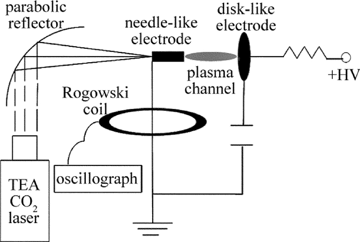
高能脉冲CO2激光诱导空气等离子体通道研究的实验装置如图 1所示。所采用的激光器为实验室自制的横向激励大气压(transverse excited atmospheric pressure, TEA) CO2激光器,波长10.6μm,脉冲能量46.5J±0.3J,10%峰值全宽约6μs。激光束经焦距500mm的离轴抛物面反射聚焦镜聚焦到两个电极之间。两电极的中心连线与聚焦激光束的光轴重合,左侧的电极为直径5cm、厚1cm的铜质圆板电极,靠近反射聚焦镜的电极为头部向圆板电极弯曲的针状电极。两电极之间,并联1个0.25μF高压电容,由高压电容充电电源对该电容充电。实验中,采用Vigo PVM-10.6探测激光脉冲波形,Thorlabs DET10A光电探测器探测等离子体发光,Tektronix P6015A高压探头探测电容电压和Pearson 4418型电流传感器探测放电电流,这些信号用数字示波器Agilent DSO-X 3024A进行记录。在进行等离子体发光的光谱分析时,采用Princeton Instruments的光谱仪SP2750和ICCD探测器PI MAX 1300。
2. 实验结果与分析
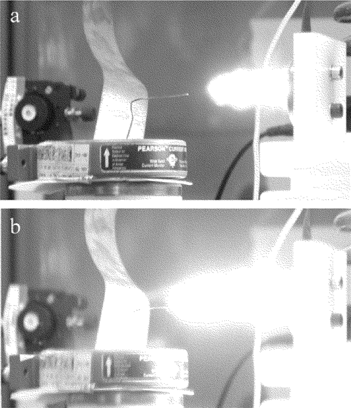
图 2中给出了用数字相机获得的激光诱导等离子体通道图样。图 2a为无外加电场时的等离子体通道。等离子体与右侧的圆板电极相连,但与左侧针状电极尚有一段距离。图 2b为有外加电场时的激光诱导放电等离子体通道的图样。此时针状电极与圆板电极间距为7.4cm,两电极间击穿之前的高压为20kV。在高压电场的作用下,等离子体向针状电极发展,最后形成了连通的放电等离子体通道。
以下报道对激光诱导放电等离子体通道的启动时间特性、电气特性、光谱特性等方面的研究结果。
2.1 激光诱导放电等离子体通道的启动时间特性
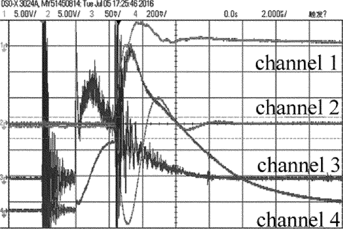
图 3中给出了激光诱导放电等离子体通道实验研究中获得的放电高压波形(通道1)、电流波形(通道2)、激光脉冲波形(通道3)及等离子体辐射波形(通道4)的典型图样。进行对应的实验时,针状电极接地,充电电源通过圆板电极对电极间并联的电容充电,充电高压为-15kV。激光器触发放电4.3μs、激光脉冲上升沿后2.3μs后,放电等离子体通道开始放电,圆板电极端高压急剧下降,等离子体的发光急剧增强。
由于使用的CO2激光脉冲能量约为50J,并且采用了放电方向与激光束方向同轴的结构,放电等离子体的启动时刻,仅比激光脉冲上升沿延后2.3μs,显著快于低激光脉冲能量时约30μs的延时[15]。
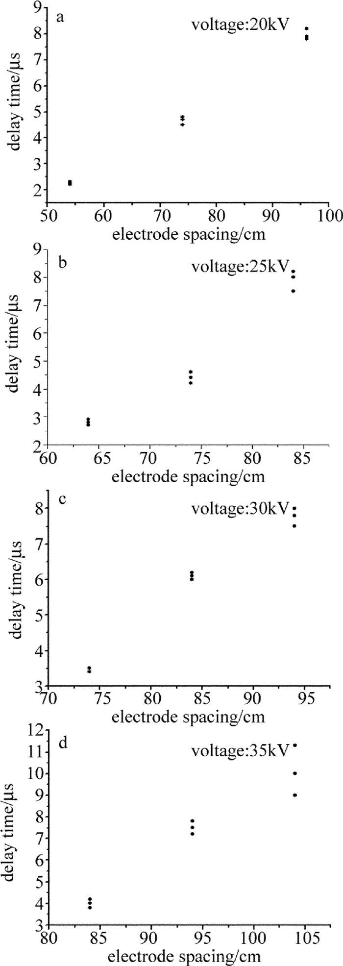
放电等离子体通道的启动时刻及其涨落与电极间距、电容充电电压等因素相关。分别做了放电电压为20kV, 25kV, 30kV和35kV下不同电极间距的放电实验。由于CO2激光能量的抖动约有600mJ,即不同束激光脉冲所能传递给带电粒子的动能也不同,所以电极间产生的初始带电粒子的初始浓度和初始速率也就不同,产生了相同电极间距以及电压条件下放电等离子体通道的启动时刻的抖动。图 4中给出了放电等离子体通道的启动时刻及其涨落与电极间距和放电电压的关系。从图中可以看出,相同电容充电电压下,放电等离子体通道的启动时刻及其涨落随着电极间距的增加而增加,但是延迟最长仅为12μs左右。
2.2 激光诱导放电等离子体通道的电气特性
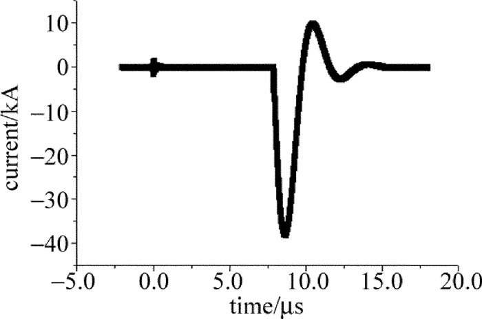
图 5是激光诱导放电的电流波形。为了了解放电等离子体通道的电气特性,采用描述电容放电电流的衰减振荡表达式对放电电流波形进行了拟合:
i=I0exp [ −(t−t0)/τ ] sin[ω0(t−t0)] (1) 式中, I0为t0时刻的电流值,ω0为电流振荡谐振频率,τ为衰减时间常数。ω0和τ与放电回路及等离子体的电气参量有关:
ω0=√1/(LC)−1/τ2 (2) τ=2L/R (3) 式中,C为储能电容的电容值,L和R为包括等离子体通道在内的放电回路电感和电阻值。
表 1为拟合得到的电极电压、等离子体长度以及激光能量对等离子体通道的影响数据。从表 1中可以看出,等离子体通道的电阻值随着电极电压增加略有减小的趋势,但受等离子体通道长度的变化影响并不是很明显。这一结果与JI等人的“等离子体通道的电阻主要为等离子体柱与电极之间的过渡区电阻”的结论[16]一致。表 1中的数据显示,即使长度超过100mm,等离子体通道的电阻也不到2Ω。这一电阻值远小于MONGIN等人报道的飞秒激光诱导的等离子体通道的电阻值。MONGIN等人的报道显示[6],采用3.9μm中红外激光,1030nm和800nm近红外激光诱导产生的长160mm的等离子体通道,电阻值分别为700GΩ, 190GΩ, 150GΩ。因此,对能量传输应用,高能脉冲CO2激光束诱导产生的等离子体通道具有明显的优势。
Table 1. Experimental data of laser induced dischargevoltage/kV plasma length/mm resistance/Ω resonant frequency/MHz fitting coefficient 20 54 1.70 1.71 0.999 20 74 1.75 1.69 0.998 20 86 1.69 1.74 0.994 20 96 1.73 1.71 0.992 25 74 1.73 1.70 0.999 25 84 1.70 1.69 0.998 30 94 1.77 1.67 0.997 35 84 1.67 1.73 0.997 35 86 1.72 1.73 0.998 35 94 1.76 1.67 0.995 35 104 1.71 1.70 0.996 35 106 1.73 1.71 0.993 2.3 激光诱导放电等离子体通道的光谱特性及等离子体密度
高功率激光击穿空气产生等离子体,等离子体中的粒子同时会向外发射出辐射,通过对等离子体的发射光谱进行分析处理可以得到等离子体中的电子密度。
目前,在计算激光诱导等离子体电子密度的众多方法中,Stark展宽法应用最为广泛。在高密度的等离子体中,由于辐射粒子会非常频繁地受到周围粒子的作用而使压力展宽远大于由自然展宽和多普勒展宽引起的谱线展宽。在这其中,辐射粒子主要是受到了周围大量电子的相互碰撞,因此可以只考虑由电子碰撞引起的Stark展宽,而忽略其它的展宽。
在实验中,作者利用Princeton Instruments的光谱仪SP2750和ICCD探测器PI MAX 1300来记录等离子体通道中343.715nm处的1价氮离子和399.5nm处的1价氧离子谱线,利用这两条谱线的Stark展宽来计算出电子密度。
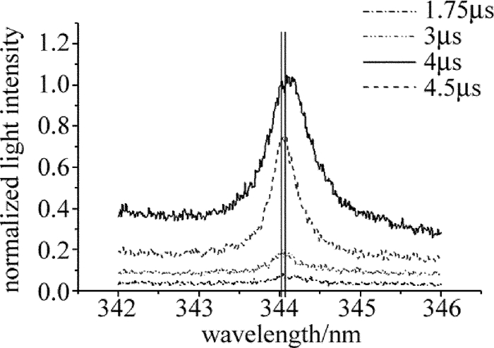
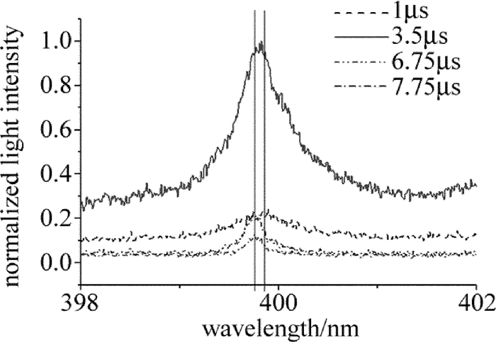
图 6为343.715nm处的1价氮离子的谱线图。图 7为399.5nm处的1价氧离子的谱线图。从图 6和图 7中可以看出,343.715nm处的1价氮离子和399.5nm处的1价氧离子的谱线在等离子体的演化过程中,中心波长会逐渐向短波方向移动,回归微弱电离等离子体的谱线位置。这个过程被称为二次Stark频移,并且在这个过程中谱线的展宽也在逐渐变小。
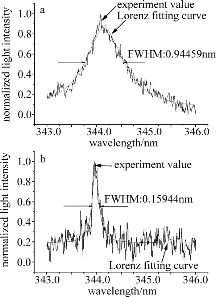
由于在仅考虑二次Stark效应的情况下,辐射谱线的线型为洛伦兹线型函数,因此可以利用洛伦兹函数对实验谱线进行拟合得到谱线的半峰全宽。图 8中给出了对时刻3.5μs和时刻6.75μs的氮离子光谱的拟合结果,拟合结果的R2分别达到0.964和0.741。
利用Stark展宽可以计算得到等离子体中电子密度,GRIEM给出了一个计算电子密度的经验公式[17]:
γ(λ)=0.2×[1+1.75α(ne1016)1/4(1−0.75r)]ω(ne1016) (4) 式中,ne是电子密度;γ为测量得到的谱线展宽,单位为nm;α为离子碰撞得到的谱线展宽参量;ω为电子碰撞引起的谱线展宽参量;r为德拜半径,单位为nm。取40000K时,ω=6.82-3,α=0.018,r=6.9×√4×10¹³/nenm。
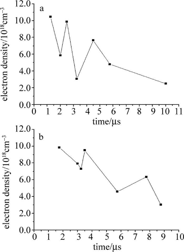
图 9为处理得到的等离子体中电子密度随时间的变化关系图。从氮离子(见图 9a)和氧离子(见图 9b)计算获得的电子密度基本相当,说明这种等离子体密度(电子密度)计算方法有较高的可靠性。图 9显示了电子密度在1019cm-3的量级,而飞秒激光等离子体通道的电子密度在1017cm-3量级[18]。尽管图 3和图 6、图 7中的等离子体辐射总功率和光谱分辨的功率均在放电前后有明显变化,但等离子体密度基本上单调减少, 这说明在脉冲激光束引发空气击穿的瞬间,等离子体密度最高,随后等离子体进入膨胀过程,即使强放电开始后,放电电流的磁压力也没能阻止等离子体的膨胀。
3. 结论
在实验上研究了TEA CO2通过离轴抛物面反射镜聚焦后,击穿空气形成等离子体通道。激光诱导等离子体通道的电阻随着电极两端电压的增加有降低的趋势,而等离子体通道长度对电阻的影响不明显。且100mm长的等离子体通道的电阻值不到2Ω,远小于同等长度的飞秒激光等离子体通道的阻抗值。此外,利用光谱仪对等离子体通道的发射光谱进行了观测,从发射光谱的Stark展宽获得了等离子体通道的等离子体密度参量。
目前,实验室正准备从完善激光束汇聚光学系统和提高脉冲激光能量两个方面入手,获得更长的激光等离子体放电通道。
-
Table 1 Experimental data of laser induced discharge
voltage/kV plasma length/mm resistance/Ω resonant frequency/MHz fitting coefficient 20 54 1.70 1.71 0.999 20 74 1.75 1.69 0.998 20 86 1.69 1.74 0.994 20 96 1.73 1.71 0.992 25 74 1.73 1.70 0.999 25 84 1.70 1.69 0.998 30 94 1.77 1.67 0.997 35 84 1.67 1.73 0.997 35 86 1.72 1.73 0.998 35 94 1.76 1.67 0.995 35 104 1.71 1.70 0.996 35 106 1.73 1.71 0.993 -
[1] SHIMADA Y, UCHIDA S, YASUDA H, et al. Laser-triggered lightning[J]. Proceedings of the SPIE, 1998, 3423:181-185. http://d.old.wanfangdata.com.cn/NSTLQK/NSTL_QKJJ02837728/
[2] SHINDO T, AIHARA Y, MIKI M, et al. Model experiments of laser-triggered lightning[J]. IEEE Transactions on Power Deliver, 1993, 8(1):311-317. DOI: 10.1109/61.180351
[3] APOLLONOV V V. Conductive channel for energy transmission[J]. American Institute of Physics Conference Proceedings, 2011, 1402(1):437-433. DOI: 10.1063/1.3657052
[4] FORESTIER B, HOUARD A, REVEL I, et al. Triggering, guiding and deviation of long air spark discharges with femtosecond laser filament[J]. American Institute of Physics Advances, 2011, 2(1):943-948. http://d.old.wanfangdata.com.cn/OAPaper/oai_doaj-articles_5343f0105dbf3f731c18e5b95be176de
[5] SCHMITT-SODY A, FRENCH D, WHITE W, et al. The importance of corona generation and leader formation during laser filament guided discharges in air[J]. Applied Physics Letters, 2015, 106(12):1-2. http://www.wanfangdata.com.cn/details/detail.do?_type=perio&id=1b44848ac7a99a4e1afce06a38324b92
[6] MONGIN D, SHUMAKOVA V, ALIŠAUSKAS S, et al. Conductivity and discharge guiding properties of mid-IR laser filaments[J]. Applied Physics, 2016, B122(10):267-273. http://ieeexplore.ieee.org/abstract/document/7789236/
[7] IONIN A A, SELEZNEV L V, SUNCHUGASHEVA E S. Formation of plasma channels in air under filamentation of focused ultrashort laser pulses[J]. Laser Physics, 2015, 25(3):033001. DOI: 10.1088/1054-660X/25/3/033001
[8] CHEN D Zh, GAO J B, YE J F, et al. Experiment study of air ionization and plasma channel conducting with nanosecond ultraviolet laser pulses[J].Laser Technology, 2008, 32(3):262-264(in Chinese). http://www.wanfangdata.com.cn/details/detail.do?_type=perio&id=jgjs200803015
[9] LIU X, LU X, ZHANG Z, et al. Triggering of high voltage discharge by femtosecond laser filaments on different wavelengths[J]. Optics Communications, 2011, 284(22):5372-5375. DOI: 10.1016/j.optcom.2011.07.058
[10] SHU X F, YU C X, LI W, et al. Kinetic-energy structure of a laser-produced-plasma channel in air[J]. Physical Review, 2015, A92(6):063844. http://www.wanfangdata.com.cn/details/detail.do?_type=perio&id=fa72c9a9f315f0c486793e61d923b0eb
[11] APOLLONOV V V. Energy transmission by laser[J]. Proceedings of the SPIE, 2015, 9255:92554K. DOI: 10.1117/12.2071198
[12] ZUO D L, CHENG Z H, LU H, et al. Studies on high energy pulsed CO2 laser[J]. Proceedings of the SPIE, 2008, 7276:72761D. DOI: 10.1117/12.823318
[13] TANG J, ZUO D, JIU Z, et al. Spectral property investigation of air plasma generated by pulsed CO2 laser[J]. IEEE Transactions on Plasma Science, 2011, 39(4):1114-1119. DOI: 10.1109/TPS.2011.2109738
[14] LAN H, WANG X B, ZUO D L. Time-resolved optical emission spectroscopy diagnosis of CO2 laser-produced SnO2 plasma[J]. Plasma Science and Technology, 2016, 18(9):902-906. DOI: 10.1088/1009-0630/18/9/05
[15] DENG X F, WANG X B, ZUO D L. Character study on CO2 laser-induced air discharge[J].Laser Technology, 2017, 4(1):61-64(in Chinese).
[16] JI Zh G, GE X Ch, WANG W Y, et al. Character study on the plasma channels produced by ultrashort laser pulses[EB/OL]. (2010-09-25). http://wenku.baidu.com/link?url=VfYXbQ2ilPLGftJdqSjYrDBOWgO6GhNGON3UzsFIBA4Skh0yH-S2CxheC1YYM9mH6aTWjKUPNQwyhLAAXHUnHOBa31uYVoE2t-isCigio9oq (in Chinese).
[17] GRIEM H R. Plasma spectroscopy[M]. New York, USA:McGraw-Hill Book Company, 1964:88-91.
[18] WANG H T, FAN Ch Y, SHEN H, et al. Temporal evolution of plasma density in femtosecond light filaments[J]. High Power Laser and Particle Beams, 2012, 24(5):1024-1028(in Chinese). DOI: 10.3788/HPLPB
-
期刊类型引用(0)
其他类型引用(1)


 下载:
下载:
