Feature analysis of coaxial monitoring of welding pool and keyhole during laser deep penetration welding
-
摘要: 为了研究激光焊接工艺参量以及焊接材料对熔池、小孔形貌的影响,搭建了激光焊接同轴监测系统,对比研究了有无辅助光源和不同工艺条件下、采用中心波长分别为532nm和808nm窄带滤光片同轴监测的熔池、小孔图像特征。结果表明,采用808nm激光辅助光源照明和808nm窄带滤光片,可清晰地拍摄到熔池、小孔以及穿透孔特征图像;相同的工艺条件下,熔池变化小,小孔动态波动且波动幅度小,穿透孔的时变动态特征较小孔则明显不同;熔池宽度随激光功率的增加而增大,随焊接速率增大而减小;不同材料激光焊接的熔池、小孔和穿透孔的同轴监测验证了本监测系统的稳定性。该研究对激光焊接质量实时监控有理论指导意义。Abstract: In order to study the influence of welding parameters and materials on the morphology of molten pool and keyhole, a coaxial monitoring system was built for fiber laser welding. The images of molten pool and keyhole were collected with 532nm and 808nm narrow band filter. Then, the 808nm laser illuminant was used to increase the light intensity of weld zone. The results indicate that, the detailed images of molten pool, keyhole and full penetration hole can be taken with 808nm narrow band filter under 808nm laser auxiliary illuminant. Under the same welding condition, molten pool and keyhole change in the stability, however, full penetration hole changes obviously with time. The change of weld pool is small. The change of small hole is dynamic and the fluctuation range is small. The dynamic characteristic of full penetration hole is obviously different from that of keyhole. The width of weld pool increases with the increase of laser power and decreases with the increase of welding speed. Coaxial monitoring of different material welding verifies the stability of monitoring system. This research provides theoretical instruction for real-time monitoring of laser welding.
-
Keywords:
- laser technique /
- laser welding /
- coaxial acquisition /
- full penetration hole
-
引言
激光焊接具有热输入小、焊接速率快、焊缝深宽比大、热影响区小、焊接精度高、易于实现自动化等突出优点[1-2],因而被大规模地应用到诸如变速箱齿轮、车身框架、底板、支柱等汽车制造业。从汽车零部件到汽车车身,激光拼焊逐步替代传统的搭接焊,成为汽车制造业主要的焊接方式之一。但由于激光光斑直径小、工件焊接热变形等问题,激光对接焊要求工件的装夹精度高,很小的组装偏差会导致焊接条件较大变化[3]。焊接焊缝质量会因激光功率、光束特性、离焦量、辅助气体和焊接速率等参量的波动受到影响[4]。激光焊接过程中,激光和基材的相互作用与耦合是在小孔中进行的[5]。小孔和穿透孔能反映焊接熔透性,熔池宽度能够反映焊缝宽度,熔池小孔监测是激光焊接质量监测的重要方法[6]。焊接过程中焊件未熔透或过熔透直接影响焊件的机械性能,因此对焊接质量进行监测很重要。
根据视觉监测系统中的传感器位置不同可将激光焊接监测分为同轴监测和旁轴监测[7]。根据有无辅助光源可将监测系统分为主动监测和被动监测[8]。被动监测不能拍摄到清晰的熔池轮廓。旁轴主动监测方法监测能采集到小孔上部图像,并采用阈值分割以及灰度形态学处理的方法提取小孔轮廓[9]。辅助光源照射到焊接区域时,熔池遮挡辅助光源形成阴影区域,通过监测阴影区域间接监测熔池形貌[10]。旁轴监测结构相对简单,但采集图像易发生畸变,需要经过图像处理还原,加大监测难度,降低监测精度。同轴监测能在监测熔池、小孔的同时监测穿透孔,采集到的焊接图像不存在畸变等问题,监测精度更高[11]。同轴监测系统在辅助光源的选择上也有差异,多数研究选择532nm附近的绿色光源[8, 12]或者808nm附近的红外光源[13-14]。图像采集设备有普通工业摄像机和高速相机。KIM等人用CCD相机作为成像设备,选用不同光源监测镀锌钢以及铝板的激光焊接,经过图像处理计算出熔池小孔的大小[15]。KIM等人以高速相机为成像设备采集了焊接过程中的小孔和穿透孔大小,并分析了小孔穿透孔随焊接参量变化的规律[12]。高速相机拍摄速率更快,能更清楚地观察到小孔、熔池动态变化过程。
多数研究集中在独立研究小孔、穿透孔或熔池,本文中以高速相机为成像设备搭建了光纤激光焊主动同轴监测系统,能够同时采集到清晰的熔池、小孔以及穿透孔图像。对比分析了有无辅助光源条件下,并采用中心波长不同的窄带滤光片同轴监测的熔池、小孔图像特征。分析了激光焊接工艺参量以及材料对熔池、小孔形貌的影响,对激光焊接熔池小孔模拟以及焊接质量实时监控有理论指导意义。
1. 同轴监测系统
1.1 试验设备
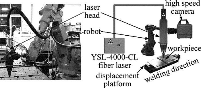
实验中采用德国IPG公司生产的YSL-4000-CL型光纤激光器及其水冷和光导系统、YW50激光焊接头。激光器的最大输出功率为4kW,连续输出,激光模式为TEM00,光束辐射波长为1.07μm,经准直聚焦系统后,最小焦斑直径为0.4mm。配合激光头载体机器人为ABB公司生产的IRB2400/16型六轴机器人,该机器人的位置精度和重复定位精度为0.03mm。本文中选用的电动平移台型号为PSA400-11-X。光纤激光焊接系统及其示意图如图 1所示。
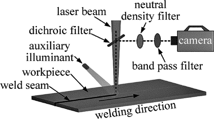
同轴图像采集设备为自主研发搭建的激光焊接同轴摄影系统,该系统主要包括808nm激光辅助光源、窄带滤波片和衰减片组成的滤光系统、互补金属氧化物半导体(complementary metal oxide semiconductor,CMOS)相机和计算机组成的图像采集系统以及相机和光源夹具。本实验中选用的高速相机是FASTCAN SA4高速相机,相机全分辨率为1024×1024像素,最大拍摄帧率为5×10⁵frames/s,最小曝光时间为1μs,感光灵敏度为6400@黑白(ISO 12232 SSAT),传感器类型为CMOS图像传感器。中性密度衰减片的透过率为50%,为讨论窄带滤波片对监测效果影响,本文中选用了中心波长分别为532nm和808nm的窄带滤波片。同时,为了能够获取清晰的熔池、小孔和穿透孔图像,需要用辅助光源对焊接区域进行照明,本文中选用的是SINTEC OPTRONICS公司的LDD-40-02T型端面抽运激光光源,其波长为(808±3)nm,最大功率为40W。
1.2 试验材料
实验中所用到的材料为HC420/780DP钢、牌号为0Cr18Ni9的304不锈钢以及TG-1钢。3种材料的化学成分如表 1所示。激光焊接试件为55mm×50mm×1.5mm的平板试件。实验前先用稀硝酸去除表面氧化物,再用丙酮清洗样件,去除表面油污。
Table 1. Chemical composition(mass fraction) of welding materialsheet element C Si Mn P S Ni Cr Alt Fe HC420/780DP ≤0.0018 ≤0.0060 ≤0.0250 ≤0.0004 ≤0.00015 — — ≥0.0001 balance 304 ≤0.0008 ≤0.0100 ≤0.0200 ≤0.00035 ≤0.0003 0.0800~ 0.1050 0.1800~ 0.2000 — balance TG-1 ≤0.0020 ≤0.0001 ≤0.0600 ≤0.00008 ≤0.00002 — ≤0.0035 — balance 1.3 试验方法
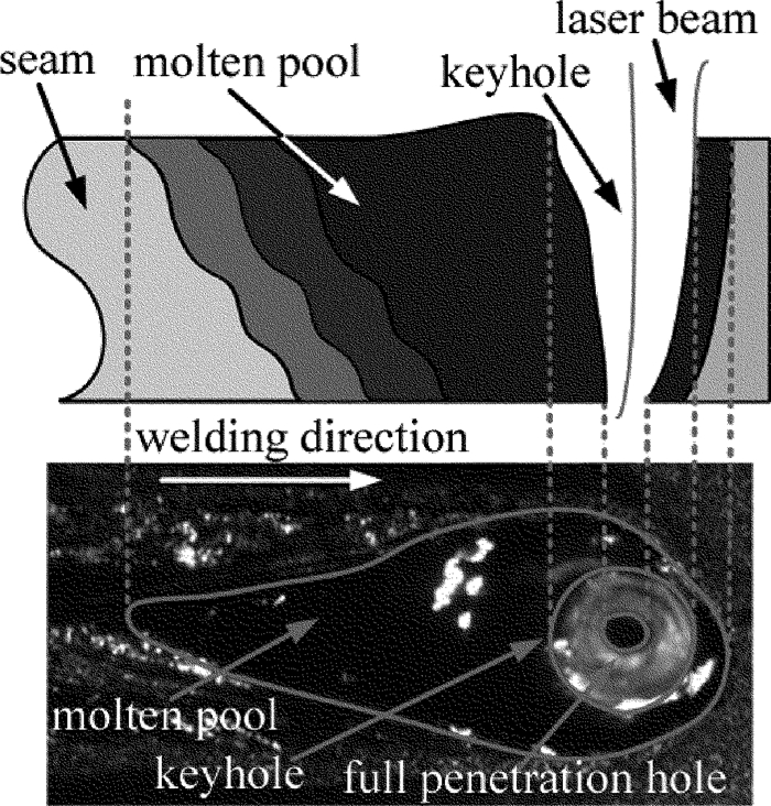
激光深熔焊接过程中焊接的熔透性缺陷直接影响焊机械强度,熔透性缺陷包括过度熔透和未熔透,而激光焊接中的小孔和穿透孔直接反映焊接的熔透性。激光深熔焊分为3种典型熔透状态:未熔透、适度熔透(小孔穿透)和过熔透。熔宽监测对焊接质量监测也很重要。焊接熔池宽度直接反映焊缝宽度,熔池过宽, 焊接热影响区过大,焊接强度降低。激光焊接的熔透特征、熔宽特征与同轴拍摄的熔池、小孔图像的相互关系原理如图 2所示。激光作用于工件表面时,材料表面被迅速地加热到沸点,材料溶化并汽化,金属蒸汽离开熔池,产生的反冲力使熔池下凹陷,形成一个细长孔洞。小孔为全焊接区域温度最高部分,小孔的光辐射强度最大。在同轴监测的图像中,白色亮斑为焊接小孔。当激光焊接熔透时, 小孔穿透板件形成穿透孔,穿透孔辐射明显减弱,在小孔中心形成暗斑。
为了采集清晰的熔池小孔图像,本文中搭建了主动式同轴监测系统,其原理图如图 3所示。因激光焊接小孔温度高达3000K[16],且光辐射大,在无任何保护衰减条件下,采集小孔图像容易造成相机光敏器件饱和,甚至损毁相机。因此,为了采集小孔图像,感光器件需要在拍摄前对辐射光进行衰减。同时,熔池区域的温度比小孔温度低约1000K[16],辐射光较小孔区域弱。感光器件在拍摄前对辐射光进行衰减后则无法采集到熔池的形貌轮廓。因此,采用同轴拍摄的方法同时采集熔池和小孔的特征信息难度大。为了解决这一矛盾,本文中提出采用辅助光源对焊接区域照明并同时使用衰减片和滤光片的方法,则可实现同时采集熔池、小孔以及穿透孔的图像。常用的辅助照明光源可选用532nm和808nm波长光源。为了选择合适的辅助光源,对比研究了有无辅助光源条件下并采用中心波长分别为532nm和808nm窄带滤光片同轴监测的熔池、小孔图像特征。同时,通过不同功率、不同速率等工艺参量的变化以及不同焊接材料的测试,验证了同轴监测激光深熔焊熔池、小孔形貌的稳定性。
2. 试验结果及分析
2.1 滤波片及辅助光源对同轴采集图像的影响
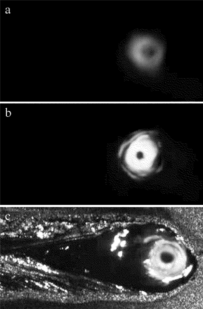
在无辅助光源条件下,分别采用中心波长为532nm和808nm窄带滤波片滤光,此时同轴监测所获得的激光焊接熔池、小孔形貌图像如图 4a和图 4b所示。在808nm激光辅助光源照明条件下,采用808nm窄带滤波片滤光同轴监测所获得的激光焊接熔池、小孔形貌图像如图 4c所示。拍摄获得图 4时所用的激光焊接工艺参量和材料均相同,其中功率为1500W,焊接速率为20mm/s,离焦量为0mm,焊接材料为HC420/780DP,相机的曝光时间均设置为50μs。对比图 4a与图 4b可以看出,采用中心波长为808nm滤光片时拍摄的同轴图像,其小孔和穿透孔更清晰。这是因为808nm属于红外波段,焊接光致等离子体/金属蒸汽干扰小,且拍摄相机的感光芯片在该波段更为敏感。对比图 4b与图 4c可以看出,增加808nm激光辅助光源照明时,不仅能获得清晰的小孔和穿透孔图像,同时还能监测到清晰的熔池图像。这种监测方法解决了温度与光辐射特征差异大的条件下,激光焊接熔池与小孔难于同时稳定监测的问题。试验结果证明,本文中搭建的主动式同轴监测系统能采集到清晰的熔池、小孔和穿透孔图像。
2.2 激光功率对熔池、小孔形貌的影响
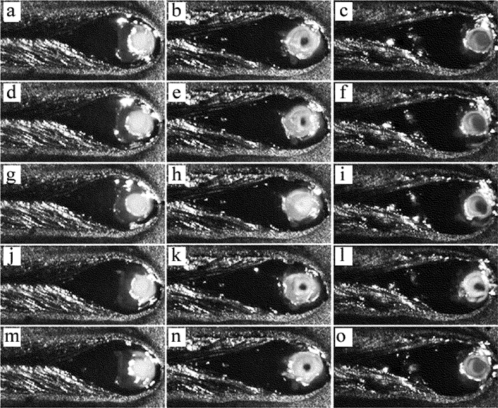
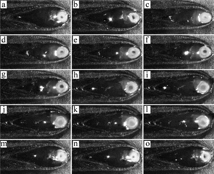
图 5是焊接速率为20mm/s、离焦量为0mm时,不同激光功率(分别为1000W, 1300W, 1600W)焊接条件下同轴采集的焊接熔池、小孔图像。图 5的每一列为相同功率参量下监测采集的连续5帧图像,每两帧时间间隔为50μs。由图可以看出,即使在相同的激光功率作用下,小孔并非稳定不变,而是动态波动。但稳定激光焊接时,小孔波动幅度小。穿透孔的时变动态特征较小孔则明显不同,即使是稳定焊接过程中,穿透孔仍会发生消失现象。如图 5所示,焊接功率为1300W时,第(t0+100)μs时刻的穿透孔消失。而在其它时刻,穿透孔清晰可见。穿透孔也不是在所有的焊接工艺条件下均会出现。当功率为1000W时,穿透孔未出现;当功率为1300W, 1600W时,穿透孔存在。穿透孔的大小也不同,功率为1300W时穿透孔的平均尺寸小于功率为1600W时穿透孔的平均尺寸。激光功率为1000W时, 焊件未熔透,未出现穿透孔;而激光功率为1600W时,焊件过熔透,明显看出穿透孔过大。穿透孔与小孔比值维持在相对稳定的状态时,焊件为适度熔透[8]。相同的激光功率下,熔池宽度稳定,但熔池宽度随激光功率的增加而增大。
![Figure 5. Dynamic changes of molten pool and keyhole images with different laser powers]() Figure 5. Dynamic changes of molten pool and keyhole images with different laser powersa—t0μs, 1000W b—t0μs, 1300W c—t0μs, 1600W d—(t0+50)μs, 1000W e—(t0+50)μs, 1300W f—(t0+50)μs, 1600W g—(t0+100)μs, 1000W h—(t0+100)μs, 1300W i—(t0+100)μs, 1600W j—(t0+150)μs, 1000W k—(t0+150)μs, 1300W l—(t0+150)μs, 1600W m—(t0+200)μs, 1000W n—(t0+200)μs, 1300W o—(t0+200)μs, 1600W
Figure 5. Dynamic changes of molten pool and keyhole images with different laser powersa—t0μs, 1000W b—t0μs, 1300W c—t0μs, 1600W d—(t0+50)μs, 1000W e—(t0+50)μs, 1300W f—(t0+50)μs, 1600W g—(t0+100)μs, 1000W h—(t0+100)μs, 1300W i—(t0+100)μs, 1600W j—(t0+150)μs, 1000W k—(t0+150)μs, 1300W l—(t0+150)μs, 1600W m—(t0+200)μs, 1000W n—(t0+200)μs, 1300W o—(t0+200)μs, 1600W2.3 焊接速率对熔池、小孔形貌的影响
图 6是激光功率均为1500W、离焦量为0mm时, 不同焊接速率(分别为20mm/s, 30mm/s, 40mm/s)条件下同轴采集的焊接熔池、小孔图像。图 6中每一列为相同焊接速率参量下监测采集的连续5帧图像,每两帧时间间隔为50μs。对比每一列可以看出,相同焊接速率条件下获得的小孔动态波动且波动幅度小。但20mm/s, 30mm/s, 40mm/s焊接速率条件下,存在穿透孔且随时间变化明显。在相同焊接速率时,同轴监测获得的熔池变化小,熔池宽度和长度均随焊接速率增大而减小。
![Figure 6. Dynamic changes of molten pool and keyhole images with different welding speeds]() Figure 6. Dynamic changes of molten pool and keyhole images with different welding speedsa—t0μs, 20mm/s b—t0μs, 30mm/s c—t0μs, 40mm/s d—(t0+50)μs, 20mm/s e—(t0+50)μs, 30mm/s f—(t0+50)μs, 40mm/s g—(t0+100)μs, 20mm/s h—(t0+100)μs, 30mm/s i—(t0+100)μs, 40mm/s j—(t0+150)μs, 20mm/s k—(t0+150)μs, 30mm/s l—(t0+150)μs, 40mm/s m—(t0+200)μs, 20mm/s n—(t0+200)μs, 30mm/s o—(t0+200)μs, 40mm/s
Figure 6. Dynamic changes of molten pool and keyhole images with different welding speedsa—t0μs, 20mm/s b—t0μs, 30mm/s c—t0μs, 40mm/s d—(t0+50)μs, 20mm/s e—(t0+50)μs, 30mm/s f—(t0+50)μs, 40mm/s g—(t0+100)μs, 20mm/s h—(t0+100)μs, 30mm/s i—(t0+100)μs, 40mm/s j—(t0+150)μs, 20mm/s k—(t0+150)μs, 30mm/s l—(t0+150)μs, 40mm/s m—(t0+200)μs, 20mm/s n—(t0+200)μs, 30mm/s o—(t0+200)μs, 40mm/s2.4 不同材料的同轴图像
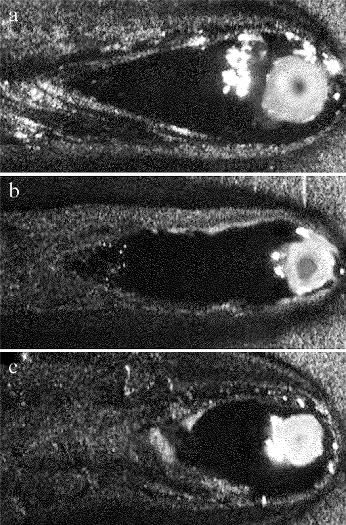
为了测试熔池小孔监测的稳定性,本文中还进行了不同材料激光焊接熔池小孔同轴监测的实验。图 7a的焊接材料为HC420/780DP钢;图 7b的焊接材料为304不锈钢,其牌号为0Cr18Ni9;图 7c的焊接材料为TG-1钢。焊接参量均相同,激光功率为1200W,离焦量为钢。焊接参量均相同,激光功率为1200W,离焦量为0mm,焊接速率均为20mm/s。从图中可以看出,不同材料激光焊接时,采用本文中搭建的同轴监测系统都能采集到清晰的熔池、小孔以及穿透孔特征信息。
3. 结论
(1) 搭建了主动式同轴激光焊接监测系统,该系统主要包括808nm激光辅助光源、衰减片和窄带滤波片组成的滤光系统、CMOS相机和计算机组成的图像采集系统以及夹具。对比分析了有无辅助光源条件下,并采用中心波长分别为532nm和808nm窄带滤光片同轴监测的熔池、小孔图像特征。采用808nm激光辅助光源照明和808nm窄带滤光片能较好地消除光致等离子体/金属蒸汽对小孔熔池形貌拍摄的干扰,可较清晰地拍摄到白色亮斑的小孔、暗斑的穿透孔以及熔池特征信息。
(2) 相同的工艺条件下,熔池变化小,小孔动态波动且波动幅度小,穿透孔的时变动态特征较小孔则明显不同。熔池宽度随激光功率的增加而增大,随焊接速率增大而减小。
(3) 不同材料激光焊接时,采用本文中搭建的同轴监测系统均能拍摄到清晰的熔池、小孔、穿透孔,验证了本监测系统的稳定性。
-
Figure 5. Dynamic changes of molten pool and keyhole images with different laser powers
a—t0μs, 1000W b—t0μs, 1300W c—t0μs, 1600W d—(t0+50)μs, 1000W e—(t0+50)μs, 1300W f—(t0+50)μs, 1600W g—(t0+100)μs, 1000W h—(t0+100)μs, 1300W i—(t0+100)μs, 1600W j—(t0+150)μs, 1000W k—(t0+150)μs, 1300W l—(t0+150)μs, 1600W m—(t0+200)μs, 1000W n—(t0+200)μs, 1300W o—(t0+200)μs, 1600W
Figure 6. Dynamic changes of molten pool and keyhole images with different welding speeds
a—t0μs, 20mm/s b—t0μs, 30mm/s c—t0μs, 40mm/s d—(t0+50)μs, 20mm/s e—(t0+50)μs, 30mm/s f—(t0+50)μs, 40mm/s g—(t0+100)μs, 20mm/s h—(t0+100)μs, 30mm/s i—(t0+100)μs, 40mm/s j—(t0+150)μs, 20mm/s k—(t0+150)μs, 30mm/s l—(t0+150)μs, 40mm/s m—(t0+200)μs, 20mm/s n—(t0+200)μs, 30mm/s o—(t0+200)μs, 40mm/s
Table 1 Chemical composition(mass fraction) of welding material
sheet element C Si Mn P S Ni Cr Alt Fe HC420/780DP ≤0.0018 ≤0.0060 ≤0.0250 ≤0.0004 ≤0.00015 — — ≥0.0001 balance 304 ≤0.0008 ≤0.0100 ≤0.0200 ≤0.00035 ≤0.0003 0.0800~ 0.1050 0.1800~ 0.2000 — balance TG-1 ≤0.0020 ≤0.0001 ≤0.0600 ≤0.00008 ≤0.00002 — ≤0.0035 — balance -
[1] LI L J. Current laser processing and equipment[M]. Beijing:Beijing Institute of Technology Press, 1993:26-30(in Chinese).
[2] WALTER W D. Laser welding[M]. New York, USA:Wiley, 1999:120-125.
[3] WANG J Ch. Development and expectation of laser welding technology[J]. Laser Technology, 2001, 25(1):48-54(in Chinese). https://www.sciencedirect.com/journal/optics-and-laser-technology
[4] GAO Sh Y, YANG Y Q, YANG K Zh. Defect detection of laser welding seam of unequal-thickness blank based on structured light vision[J]. Laser Technology, 2011, 35(4):440-443(in Chinese). http://en.cnki.com.cn/Article_en/CJFDTOTAL-JGJS201104003.htm
[5] CHEN G Y, LI Ch Z, ZHOU C, et al. Partial penetration welding of 5A06 aluminum alloy with high power fiber laser[J]. Laser Technology, 2015, 39(2):170-175(in Chinese). http://www.en.cnki.com.cn/Article_en/CJFDTOTAL-JGJS201601005.htm
[6] GAO J Q, QIN G L, YANG J L, et al. Image processing of weld pool and keyhole in Nd:YAG laser welding of stainless steel based on visual sensing[J]. Transactions of Nonferrous Metals Society of China, 2011, 21(2):423-428. DOI: 10.1016/S1003-6326(11)60731-0
[7] SHAO J, YAN Y. Review of techniques for on-line monitoring and inspection of laser welding[J].Journal of Physics:Conference Series, 2005, 15(1):101-107. http://adsabs.harvard.edu/abs/2005JPhCS..15..101S
[8] ZHANG Y, ZHANG C, TAN L, et al. Coaxial monitoring of the fibre laser lap welding of Zn-coated steel sheets using an auxiliary illuminant[J]. Optics & Laser Technology, 2013, 50(2):167-175. http://www.sciencedirect.com/science/article/pii/S0030399213000546
[9] TENNER F, BROCK C, KLÄMPFL F, et al. Analysis of the correlation between plasma plume and keyhole behavior in laser metal welding for the modeling of the keyhole geometry[J]. Optics and Lasers in Engineering, 2015, 64(12):32-41. http://www.sciencedirect.com/science/article/pii/S014381661400181X
[10] GAO X, ZHANG Y. Monitoring of welding status by molten pool morphology during high-power disk laser welding[J]. Optik-International Journal for Light and Electron Optics, 2015, 126(19):1797-1802. DOI: 10.1016/j.ijleo.2015.04.060
[11] LUO M, SHIN Y C. Vision-based weld pool boundary extraction and width measurement during keyhole fiber laser welding[J]. Optics and Lasers in Engineering, 2015, 64(12):59-70. http://d.old.wanfangdata.com.cn/NSTLQK/NSTL_QKJJ0234311408/
[12] KIM J, OH S, KI H. A study of keyhole geometry in laser welding of zinc-coated and uncoated steels using a coaxial observation method[J]. Journal of Materials Processing Technology, 2015, 225:451-462. DOI: 10.1016/j.jmatprotec.2015.06.029
[13] OEZMERT A, DRENKER A, NAZERY V. Detectability of penetration based on weld pool geometry and process emission spectrum in laser welding of copper[J]. Physics Procedia, 2013, 41:509-514. DOI: 10.1016/j.phpro.2013.03.108
[14] REGAARD B, FIEDLER W, KAIERLE S. Error detection in lap welding applications using on-line melt pool contour analysis by coaxial process monitoring with external illumination[J]. Physics Procedia, 2007, 41:471-475. http://cn.bing.com/academic/profile?id=88d7796c7e4276df7347fe530bae6246&encoded=0&v=paper_preview&mkt=zh-cn
[15] KIM C H, AHN D C. Coaxial monitoring of keyhole during Yb:YAG laser welding[J]. Optics & Laser Technology, 2012, 44(6):1874-1880. http://www.sciencedirect.com/science/article/pii/S0030399212000801
[16] PANG S, HIRANO K, FABBRO R, et al. Explanation of penetration depth variation during laser welding under variable ambient pressure[J]. Journal of Laser Applications, 2015, 27(2):022007. DOI: 10.2351/1.4913455


 下载:
下载:
