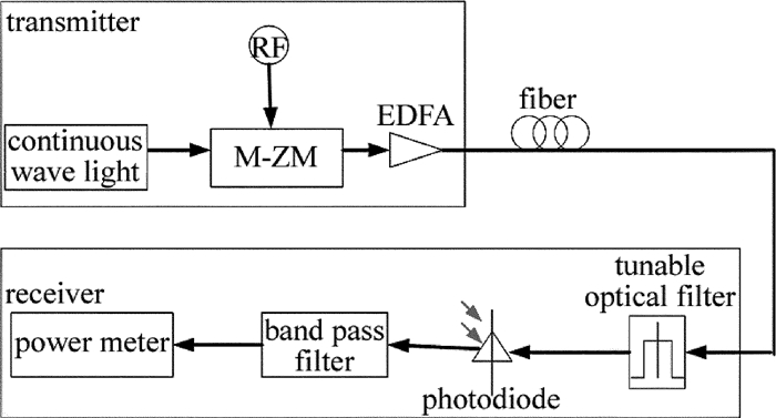
Dispersion measuring technique based on second order lowest power of radio frequency signal
-
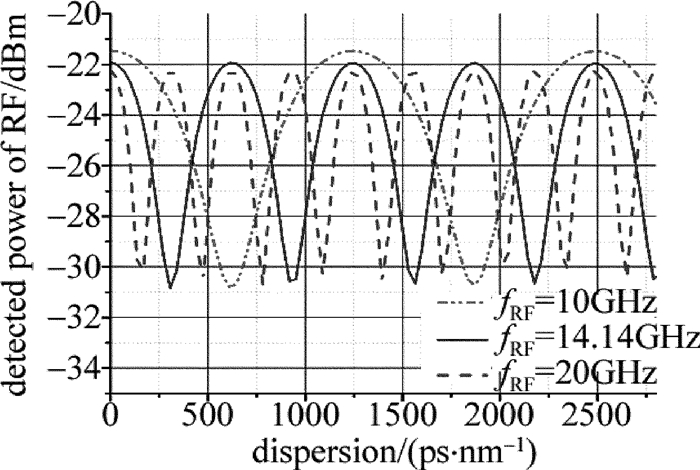
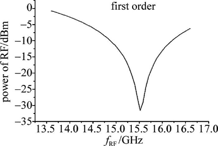
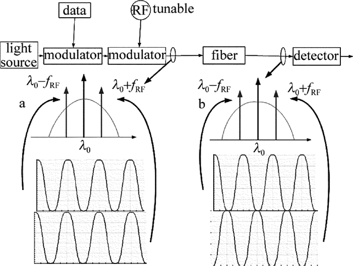
摘要: 为了适应高速率大色散光纤信道对链路色散的精确补偿要求,研究并提出了一种基于射频信号2阶零功率点的信道色散测量方案。采用信号两边带的位相差来测量光纤链路中的色散值,通过在发射端加载射频信号,可以得到接收端射频信号功率大小随链路色散值的周期性变化关系,从仿真光纤链路色散随射频信号频率的变化曲线获得接收端射频信号2阶零功率点位置。结果表明,基于射频信号2阶零功率的信号测量方案色散测量误差可控制在±10ps/nm范围内。相较于1阶零功率点,基于射频信号2阶零功率点信道色散测量方案可满足高速率、长距离大色散光纤信道对色散值的精确测量需求。Abstract: In order to meet the need of precise compensation of chromatic dispersion in optical fiber link with long distance and high bit rate, channel dispersion measurement technique based on second order lowest power of radio frequency (RF) signal was studied and demonstrated. The chromatic dispersion in optical fiber link was measured by the phase difference between RF signals that loaded to two sidebands of spectrum. By loading RF signal on the transmitter, the periodic relationship between the power of RF signal in the receiver and optical fiber dispersion was obtained. The position of second lowest RF signal power was gotten by simulation of relationship curve between the power of RF signal in the receiver and optical fiber dispersion. The results show that, the dispersion measuring error in this system is in the range of ±10ps/nm. Comparing with the technique based on first order lowest power of RF signal, dispersion measuring technique based on second order lowest power of RF signal can satisfy the need of measuring large fiber dispersion for high chromatic dispersion value.
-
-
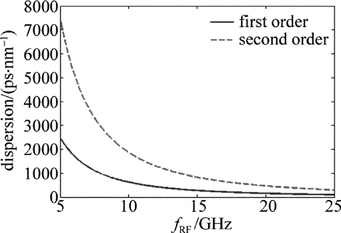
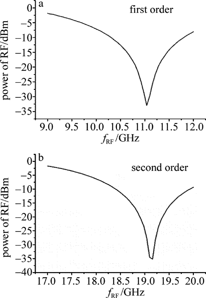
Table 1 Dispersion value of first order and second order lowest power under different RF fRF
fRF/GHz first order/(ps·nm-1) second order/(ps·nm-1) 10 621 1863 14.14 311 934 20 153 460 Table 2 Comparing of the calculated fiber dispersion vs. the actual fiber dispersion
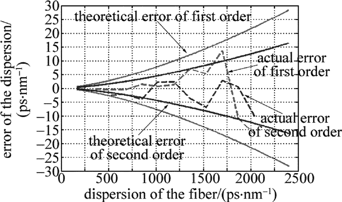
actual value/(ps·nm-1) f01/GHz calculated value by equation (3)/(ps·nm-1) f02/GHz calculated value by equation (4)/(ps·nm-1) 340 15.52 339.73 > 20 510 11.04 509.51 19.16 507.48 680 9.56 679.48 16.56 677.71 850 8.54 851.48 14.84 845.95 1020 7.8 1020.70 13.5 1022.22 1190 7.22 1191.29 12.5 1192.32 1360 6.74 1367.01 11.72 1356.30 1530 6.36 1535.24 11.06 1523.01 1700 6.02 1713.56 10.46 1702.74 1870 5.78 1858.81 9.98 1870.47 2040 5.54 2023.35 9.58 2029.93 -
[1] QUE L, YIN X. Analysis of dispersion tolerance in optical communication[J].Study of Optical Communications, 2008, 150(6):14-16(in Chinese). http://en.cnki.com.cn/Article_en/CJFDTOTAL-GTXY200806006.htm
[2] CAO X. Optimization of dispersion compensation in optical fiber communication systems[J].Laser Technology, 2014, 38(1):101-104(in Chinese). http://en.cnki.com.cn/Article_en/CJFDTotal-JGJS201401022.htm
[3] GLENTIS G O, GEORGOULAKIS K, ANGELOPOULOS K. Dispersion compensation of fiber links using pruned volterra equalizers[C]//Advanced Photonics 2015 OSA Technical Digest.New York, USA: Optical Society of America, 2015: JM3A.7.
[4] ZHOU Zh Q, TANG Y L, XIE Ch J. Optimum schemes of dispersion compensation transmission systems using dispersion compensation fibers[J].Laser Technology, 2000, 24(5):265-269(in Chinese). http://en.cnki.com.cn/Article_en/CJFDTOTAL-JGJS200005003.htm
[5] KAWAKAMI H, YOSHIDA E, HUBOTA H, et al. Novel signedchromatic dispersion monitoring technique based on asymmetric waveform distortion in DQPSK receiver[C]//Conference on Opto-electronics & Communications. New York, USA: IEEE, 2008: 1-2.
[6] LI B, LUO F G, ZHOU W, et al. Chromatic dispersion measurement using single sideband spectrum phase difference detection for OOK signal link[J].Optics Express, 2011, 19(25):25583-25592. DOI: 10.1364/OE.19.025583
[7] LI B, LUO F G, TIAN M, et al. Fiber chromatic dispersion measurement by using a novel RF spectrum phase detection based on DSP[J].Optics Communications, 2012, 285(15):3249-3253. DOI: 10.1016/j.optcom.2012.02.085
[8] WESTBROOK P S, EGGLETON B J, RAYBON G, et al. Measurement of residual chromatic dispersion of a 40-Gb/s RZ signal via spectral broadening[J].IEEE Photonics Technology Letters, 2002, 14(3):346-348. DOI: 10.1109/68.986808
[9] VO T D, PELUSI M D, SCHRODER J, et al. Simultaneous multi-impairment monitoring of 640Gb/s signals using photonic chip based RF spectrum analyzer[J].Optics Express, 2010, 18(4):3938-3945. DOI: 10.1364/OE.18.003938
[10] SORIANO R A, HAUSKE F N, GONZALEZ N G, et al. Chromatic dispersion estimation in digital coherent receiver[J].Journal of Lightwave Technology, 2011, 29(11):1627-1637. DOI: 10.1109/JLT.2011.2145357
[11] YAO S, ERIKSSON T A, FU S, et al. Fast and robust chromatic dispersion estimation based on temporal auto-correlation after digital spectrum superposition[J].Optics Express, 2015, 23(12):15418-15430. DOI: 10.1364/OE.23.015418
[12] WANG D, LU C, LAU A P T. Adaptive chromatic dispersion compensation for coherent communication systems using delay-tap sampling technique[J].Photonics Technology Letters, 2011, 23(14):1016-1018. DOI: 10.1109/LPT.2011.2151280
[13] WANG Y, HU S, YAN L, et al. Chromatic dispersion and polarization mode dispersion monitoring for multi-level intensity and phase modulation systems[J].Optics Express, 2007, 15(21):14038-14043. DOI: 10.1364/OE.15.014038
[14] YU C, YANG J. CD and PMD monitoring based on RF spectrum analysis with optical filtering[C]//Communications and Photonics Conference and Exhibition (ACP), 2010 Asia.New York, USA: IEEE, 2010: 419-420.
[15] RIBEIRO V, COSTA L, TEIXEIRA A, et al. Chromatic-dispersion-monitoring scheme using a Mach-Zehnder interferometer and Q-factor calculation[J].Journal of Optical Communications and Networking, 2010, 2(1):10-19. http://d.old.wanfangdata.com.cn/NSTLQK/NSTL_QKJJ0219479237/
[16] HE F L, LIU M, DONG Ch P, et al. Research of dispersion characteristics of square-lattice all solid photonic bandgap fibers[J].Laser Technology, 2012, 36(1):90-92(in Chinese). http://www.wanfangdata.com.cn/details/detail.do?_type=perio&id=jgjs201201023
[17] LI B. Investigation of dispersion monitoring technology for ultra-high speed optical transmission link[D].Wuhan: Huazhong University of Science and Technology, 2012: 1-116(in Chinese).


 下载:
下载:
