Optimization of Stokes optical polarization measurement system
-
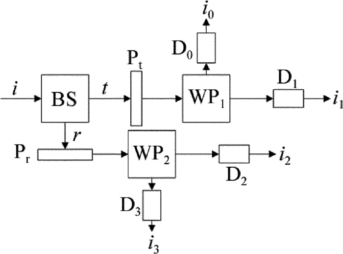
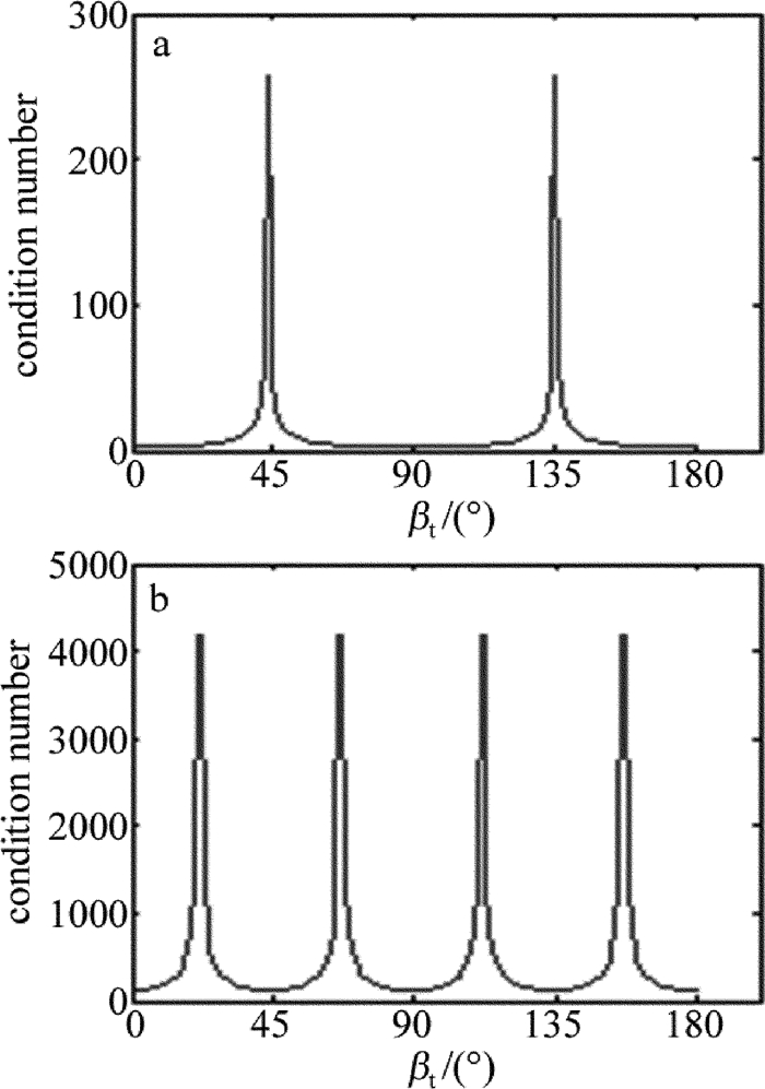
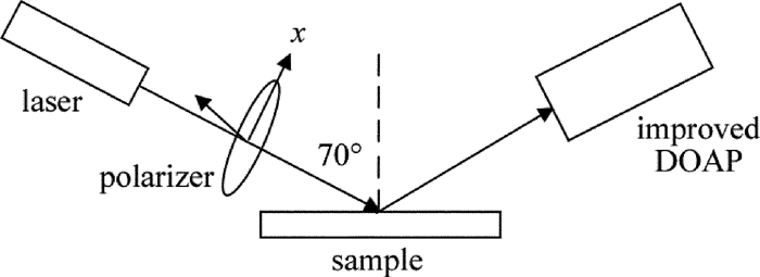
摘要: 为了满足光偏振态分振幅测量模块(DOAP)对分光棱镜复杂且严格的加工要求,采用在经典DOAP透射光路及反射光路各引入一块波片的方法,组成改进后的光偏振态测量模块。推导了新的仪器矩阵表达式,通过分析波片参量对仪器矩阵条件数的影响,得到了最佳波片的参量及其关系。结果表明,优化后的斯托克斯椭偏仪测量薄膜样品的厚度和折射率的标准差分别为0.1nm和0.001。通过选择波片的最佳方位角或相位延迟量可以实现斯托克斯椭偏仪仪器矩阵的优化,从而提高系统的测量稳定性及可靠性。Abstract: Division-of-amplitude photopolarimeter(DOAP) was the key part of Stokes ellipsometer. To reach the complex and strict processing demands of beam splitter in DOAP, two waveplates are inserted respectively in the reflection light path and transmittion light path of classic DOAP to form an improved DOAP. The instrument matrix of new DOAP was derived and influence of waveplate parameters on the condition number of instrument matrix was also analyzed. From theoretical analysis and experimental verification, the optimal parameters and their relationships of waveplates were gotten. The results show that, measurement standard errors of film thickness and refractive index of the optimized Stokes ellipsometer are 0.1nm and 0.001 respectively. By choosing the optimal azimuthal angles or phase retardations of waveplates, the instrument matrix can be optimized to improve the accuracy and stability of measurement.
-
-
Table 1 Measurement results of Stokes ellipsometer before and after the insert of wave-plate
no wave-plate quarter wave-plate at 45° quarter wave-plate at 90° reference value condition number 156.53 171.08 32.63 — sample 1 thickness/nm 95.3±0.9 95.1±0.9 102.1±0.1 101.84±0.04 refractive index 1.550±0.006 1.528±0.009 1.454±0.001 1.460±0.001 sample 2 thickness/nm 144.7±0.9 142.8±0.9 162.9±0.1 162.03±0.05 refractive index 1.565±0.007 1.571±0.011 1.460±0.001 1.463±0.001 sample 3 thickness/nm 109.0±1.1 113.2±1.2 184.9±0.1 185.19±0.04 refractive index 1.931±0.009 1.775±0.014 1.455±0.001 1.454±0.001 -
[1] XIAO G H, HUANG Z H, LIU Ch N, et al. Analysis of ellipsometric data processing about transparent film on the transparent substrate[J]. Laser Technology, 2010, 34(2):247-249(in Chinese). http://www.wanfangdata.com.cn/details/detail.do?_type=perio&id=jgjs201002032
[2] CHENG M X, HE Zh J, HUANG Z H. A method of ellipsometry based on Stokes parameters with a division-of-amplitude polarimeter(DOAP) system[J]. Opto-Electronic Engineering, 2009, 36(7):100-106(in Chinese). http://www.wanfangdata.com.cn/details/detail.do?_type=perio&id=gdgc200907019
[3] LÜ X, JIANG Zh Q, LI Y Ch. Study on the measurement of SOP with high-speed and real-time[J]. Optical Technique, 2010, 36(6):866-870(in Chinese). http://www.wanfangdata.com.cn/details/detail.do?_type=perio&id=gxjs201006015
[4] QIN Z Y, CHENG Z G, ZHANG Z P, et al. High-speed and real-time measurement of Stokes parameters[J]. Acta Optica Sinica, 2007, 27(4):659-662(in Chinese).
[5] LIN H H, PHAN Q H, LO Y L. Characterization of voltage-driven twisted nematic liquid crystal cell by dynamic polarization scanning ellipsometry[J]. Optics Express, 2015, 23(8):10213-10223. DOI: 10.1364/OE.23.010213
[6] HALL S A, COVERT P A, BLINN B R, et al. Rapid and sensitive polarization measurement for characterizing protein adsorption at the solid-liquid interface[J]. Journal of Physical Chemistry, 2013, C117(4):1796-1803. http://www.wanfangdata.com.cn/details/detail.do?_type=perio&id=81ba8f81cdcc7b7524309d3c7394aebd
[7] LO Y L, HSIEH W H, CHUNG Y F, et al. An approach for measuring the ellipsometric parameters of isotropic and anisotropic thin films using the stokes parameter method[J]. Journal of Lightwave Technology, 2012, 30(14):2299-2306. DOI: 10.1109/JLT.2012.2196977
[8] CHENG M X, HE Z J, HUANG Z H. Measurement and application of stokes parameters of polarized light[J]. Infrared and Laser Engineering, 2006, 35(s2):109-115(in Chinese). http://en.cnki.com.cn/Article_en/CJFDTOTAL-HWYJ2006S2026.htm
[9] XU X S. The design of an experimental study of polarimeter system of Stokes parameters based on division-of-amplitude[D]. Hangzhou: Zhejiang University, 2011: 44-52(in Chinese).
[10] AZZAM R M A. Division-of-amplitude photopolarimeter (DOAP) for the simultaneous measurement of all four Stokes parameters of light[J]. Optica Acta, 1982, 29(5):685-689. DOI: 10.1080/713820903
[11] AZZAM R M A. Division-of-amplitude photopolarimeter based on conical diffraction from a metallic grating[J]. Applied Optics, 1992, 31(19):3574-3576. DOI: 10.1364/AO.31.003574
[12] AZZAM R M A, SUDRADJAT F F. Single-layer-coated beam splitters for the division-of-amplitude photopolarimeter[J]. Applied Optics, 2005, 44(2):190-196. DOI: 10.1364/AO.44.000190
[13] TAYA S A, EI-AGEZ T M, ALKANOO A A. Ellipsometric configurations using a phase retarder and a rotating polarizer and analyzer at any speed ratio[J]. Chinese Physics, 2012, B21(11):110701. http://www.wanfangdata.com.cn/details/detail.do?_type=perio&id=QK201206191230
[14] YUAN W J, SHEN W D, ZHANG Y G, et al. Dielectric multilayer beam splitter with differential phase shift on transmission and reflection for division-of-amplitude photopolarimeter[J]. Optics Express, 2014, 22(9):11011-11020. DOI: 10.1364/OE.22.011011
[15] AZZAM R M A. Beam splitters for the division-of-amplitude photopolarimeter[J]. Optica Acta, 1985, 32(11):1407-1412. DOI: 10.1080/713821665
[16] AZZAM R M A. Optimal beam splitters for the division-of-amplitude photopolarimeter[J]. Journal of the Optical Society of America, 2003, A20(5):955-958. http://www.wanfangdata.com.cn/details/detail.do?_type=perio&id=fa292fc8b5f0222683451abeb02dff67
[17] REN Sh F, WANG X X. Polarization states of linearly polarized light transmitting through several wave-plates with arbitrary thickness[J]. Laser Technology, 2014, 38(3):394-397(in Chinese). http://www.wanfangdata.com.cn/details/detail.do?_type=perio&id=jgjs201403024
[18] ZHANG Y, HUANG Z H, ZHAO Z T, et al. In-place calibration of Stokes ellipsometer's instrument matrix[J]. Acta Optica Sinica, 2013, 33(2):0212002(in Chinese). DOI: 10.3788/AOS
[19] WANG Y H, ZHENG C L, ZHAO Z T. Muti-point calibration method based on Stokes ellipsometry system[J]. Chinses Journal of Lasers, 2012, 39(11):1108013(in Chinese). DOI: 10.3788/CJL


 下载:
下载:


