Characteristics of air discharges triggered by CO2 laser
-
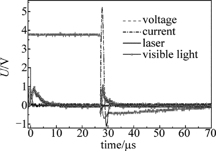
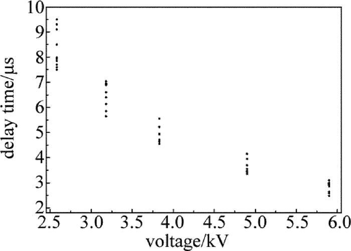
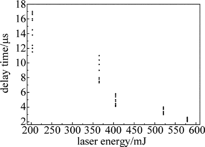
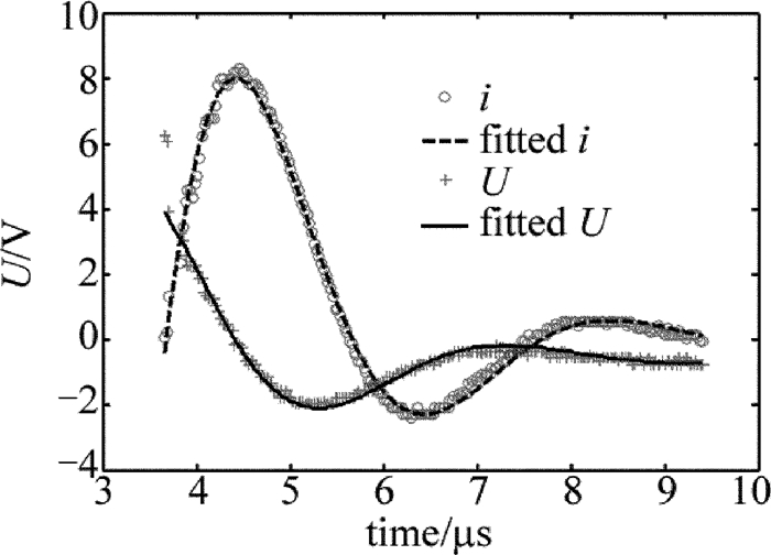
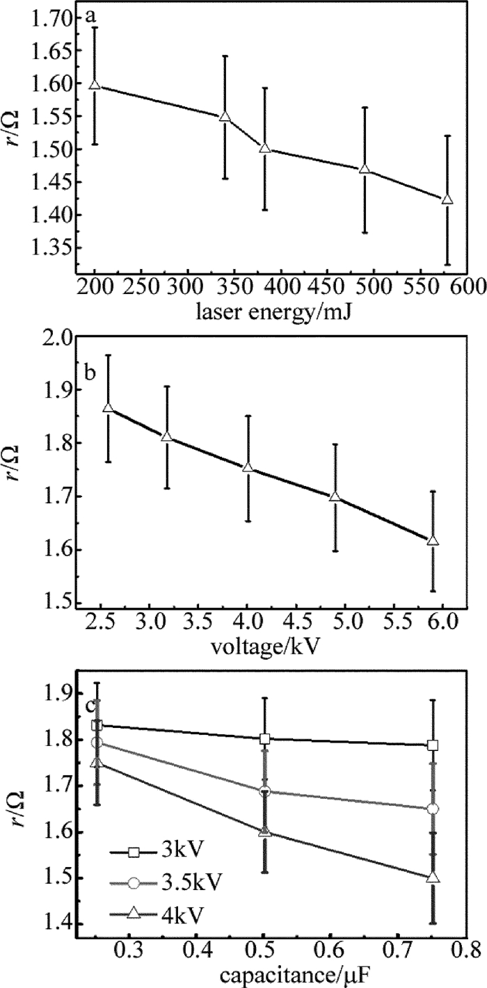
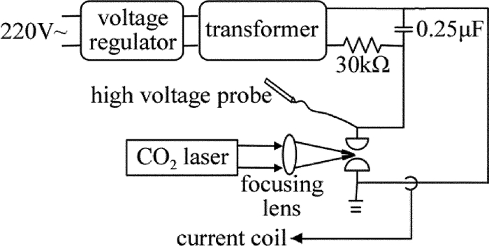
摘要: 为了研究脉冲CO2激光诱导空气放电的特性,建立了高压电容充放电实验平台,采用间距为8mm、半径为10mm的一对球形石墨电极,取得了放电电压和电流的实时数据,采用2阶振荡电路模型对放电电压和放电电流进行拟合得到了电极间激光诱导放电等离子体的阻抗,并对放电时间、放电延时及抖动做了统计。结果表明,激光诱导放电等离子体的阻抗很小,约1Ω~2Ω,拟合得到的放电等离子体阻抗随放电电压、放电电容、以及激光能量的增加而减小;放电延时随着实验条件的变化在2μs~10μs之间变化,放电延时以及延时抖动随着放电电压和激光能量的增加而降低,而受放电电容大小的影响不明显。由此高稳定性的激光脉冲和高压有助于激光诱导放电过程的稳定。Abstract: In order to investigate the characteristics of pulsed CO2 laser triggering discharge, a high voltage capacitance discharge experimental platform was set up by a pair of hemisphere graphite electrode with 10mm radius and 8mm gap. The real-time data of discharge voltage and current were obtained. Discharge voltage and discharge current were fitted by two-order oscillation circuit model. The impedance of laser induced discharge plasma was obtained. And the discharge time, discharge delay and jitter data were collected. The results show that the impedance of laser trigger discharge plasma is very little, and of 1Ω~2Ω. The fitted plasma impedance slightly decreases with the increase of laser energy, discharge voltage and capacitance. The delay varies from 2μs to 10μs with the change of experimental condition. Delay and delay jitter decrease with the increase of laser energy and discharge voltage. Discharge capacitance has no obvious effects on delay and delay jitter. Laser pulse and high voltage with high stability are helpful for the stability of laser triggered discharges.
-
Keywords:
- laser optics /
- CO2 laser /
- pulse discharge /
- plasma /
- air
-
-
Table 1 Data statistics of laser triggered discharge
U/kV E=579mJ,
C=0.25μFE/mJ U=6.85kV,
C=0.25μFC/μF U=3.5kV,
E=579mJImax/A t/μs Imax/A t/μs Imax/A t/μs 2.58 356 0.653 203 793 0.708 0.25 468 0.677 3.18 444 0.668 365 793 0.708 0.5 386 1.38 3.83 565 0.695 405 793 0.708 0.75 312 1.97 4.90 686 0.701 521 793 0.708 5.90 726 0.705 579 793 0.708 -
[1] YAMAURA M, IHARA S, SATOH S, et al. Characteristics of a laser-triggered discharge by high-repetition-rate excimer laser on dc electric field[J]. Proceedings of the SPIE, 2000, 3886:207-214. DOI: 10.1117/12.375111
[2] ACKERMANN R, STELMASZCZYK K, ROHWETTER P, et al. Triggering and guiding of megavolt discharges by laser-induced filaments under rain conditions[J]. Applied Physics Letters, 2004, 85(23):5781-5783. DOI: 10.1063/1.1829165
[3] FUJⅡ T, MIKI M, GOTO N, et al. Leader effects on femtosecond-laser-filament-triggered discharges[J]. Physics of Plasmas, 2008, 15(1):981-984. http://d.old.wanfangdata.com.cn/NSTLQK/NSTL_QKJJ028837556/
[4] AKYUZ M, RAHMAN M, LARSSON A, et al. Characteristics of laser-triggered electric discharges in air[J]. IEEE Transactions on Dielectrics and Electrical Insulation, 2005, 12(5):1060-1070. DOI: 10.1109/TDEI.2005.1522198
[5] MIKI M, WADA A, SHINDO T. Model experiments of laser-triggered lightning using an intense CO2 laser pulse[J].Proceedings of the SPIE, 2000, 3886:680-690. DOI: 10.1117/12.375169
[6] HOSHI Y, YOSHIDA H. Examination of laser-triggered discharge using a virtual gas model and the similarity of its Paschen curve with those of inert gases[J]. Journal of Applied Physics, 2009, 106(6):066103. DOI: 10.1063/1.3223536
[7] ZHAN J, YANG M J. Investigation on the breakdown voltage induced by YAG pulsed laser[J]. Laser Technology, 2009, 33(2):138-140(in Chinese). http://www.wanfangdata.com.cn/details/detail.do?_type=perio&id=jgjs200902018
[8] ZHAN J, YANG M J. Investigation on the voltage-current characteristics of the YAG laser guiding discharge channel[J]. Laser Journal, 2008, 28(5):17-19(in Chinese). http://www.wanfangdata.com.cn/details/detail.do?_type=perio&id=jgzz200805007
[9] YIN Y, YANG J, ZHONG L H, et al. Triggering delay and jitter of laser triggered gas switch[J]. High Voltage Engineering, 2014, 40(1):194-200(in Chinese). http://en.cnki.com.cn/Article_en/CJFDTotal-GDYJ201401028.htm
[10] WANG J F, TANG X Z. Testing study of gap flashover triggered by laser-plasma[J]. High Voltage Engineering, 1999, 25(2):18-20(in Chinese). http://en.cnki.com.cn/Article_en/CJFDTOTAL-GXKZ200002000.htm
[11] LIU Z F, WEI W B, DONG Q X, et al. Experimental study on air gap discharge triggered by pulsed laser under HVDC condition[J]. Proceedings of the CSEE, 2014, 34(21):3527-3533(in Chinese). http://www.wanfangdata.com.cn/details/detail.do?_type=perio&id=zgdjgcxb201421017
[12] CHEN D Z, GAO J B, YE J F, et al. Experiment study of air ionization and plasma channel conducting with nanosecond ultraviolet laser pulses[J]. Laser Technology, 2008, 32(3):262-264(in Chinese). http://www.wanfangdata.com.cn/details/detail.do?_type=perio&id=jgjs200803015
[13] ARANTCHOUK L, POINT G, BRELET Y, et al. Large scale Tesla coil guided discharges initiated by femtosecond laser filamentation in air[J]. Journal of Applied Physics, 2014, 116(1):013303. DOI: 10.1063/1.4886582
[14] TANG J, ZUO D L, YANG C G, et al. Spectroscopic diagnosis of air plasma induced by pulsed CO2 laser[J]. Laser Technology, 2013, 37(5):636-641(in Chinese). http://en.cnki.com.cn/Article_en/CJFDTOTAL-JGJS201305017.htm


 下载:
下载:
