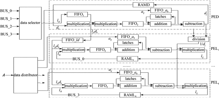
Locating algorithm of optical fiber spot center based on FPGA
-
摘要: 为了解决传统数字图像处理算法中数据运算量大、复杂度高、耗时长的问题,提出一种基于可编程门阵列(FPGA)光纤光斑中心定位的方法。采用数字信号处理系统,利用开发工具(DSP builder),设计了光斑图像预处理算法和边缘检测算法,用最小二乘法拟合光斑边界,采用流水线设计,增强了数据处理的并行能力,提高了处理速度。在Cyclone V平台上进行理论分析和实验验证,取得了光斑图像边界、中心坐标数据。结果表明,在保证对光斑中心定位的绝对误差小于0.1pixel的条件下,使用FPGA比计算机运算速度能提高21倍以上。该研究能够在FPGA平台上快速准确定位光斑中心。Abstract: In order to solve the problem of large amount of data, high complexity and long time consuming in traditional digital image processing algorithm, a method for center location of optical fiber spot was presented based on field-programmable gate array (FPGA). By using digital signal processing system and development tools (DSP builder), image preprocessing algorithm and edge detection algorithm were designed. The least square method was used to fit the boundary of light spot. The parallel capability for data processing was enhanced and the processing speed was improved by means of pipeline design. Theoretical analysis and experimental verification were carried out on Cyclone V platform. The image boundary and the central coordinate data were obtained. The results show that under the condition that the absolute error of spot center location is less than 0.1pixel, the computer speed can be improved by more than 21 times based on FPGA. The spot center can be located quickly and accurately on FPGA platform.
-
Keywords:
- image processing /
- spot center detection /
- least square method /
- optical fiber spot
-
引言
传统光学器件通过在传播路径上的相位或者偏振累加效应对入射光进行波前调制,实现了光束聚焦、偏振转换、全息成像等光学功能[1-2]。这样的工作原理要求器件本身的尺寸必须大于入射光波长。随着光学集成度的需求逐渐提高,大尺寸和质量的传统光学元件已经不能满足设计要求,因此, 小尺寸和轻质量的光学元件研究成为当今光学领域的一个研究热点,其中光学超表面材料就是其中一个重要方向。超表面材料指的是厚度小于入射光波长的一类人工超材料,相对于入射光波长尺寸,超表面可以视为是一种2维结构。超表面通常是由周期性亚波长散射体结构或者是光学细膜结构组成,对入射光进行波前调制的原理是基于界面处相位突变[3-4]。哈佛大学CAPASSO小组在2011年首先提出了光学超表面的概念,设计出了基于V型金属天线超表面结构,实现了红外波段的相位调制[5]。自此基于超表面的新型光学器件成为了研究热点,即打开了一扇在2维平面内而不是3维空间中调控光强度、相位分布和偏振的大门,例如异常透射现象、光学波片、光学透镜、光学全息[6-8]和涡旋波束产生器[4, 9-11]等。
涡旋光束首先由ALLEN等人于1992年实现[12]。最近的研究显示, 利用超表面材料可以有效产生和调控涡旋光束,例如使用V型天线阵列超表面[9-10]或者全介质棒状天线超表面[4, 11]。
需要注意的是,这些研究绝大多数都是利用超表面产生和调控1阶涡旋光束,很少出现高阶模式的研究[3-11]。
使用V型天线阵列在界面处产生相位突变,实现各种功能的超表面是一类比较流行的设计方法。V型天线的几何尺寸,例如臂长、张角和开口方向等,决定了天线的电磁波散射特性。从样品加工的角度来看,基本单元越简单,自由度越少,加工难度越小。例如对于V型天线而言,开口方向较难控制。L型金属天线是一类特殊的V型天线,其自由度只有臂长和臂宽两个自由度,这两个自由度在实际加工过程很容易控制,而且L型金属天线也避免了开口方向这个比较难控制的自由度。因此这一类的天线散射单元具有研究价值,例如研究L型天线单元的透射的偏振转化特性[13-14]、L型天线单一结构阵列产生涡旋光束的研究[5]。
本文中利用L型金属天线阵列超表面设计了1阶和2阶太赫兹波涡旋光束产生器件。数值计算结果表明, 线偏太赫兹波垂直入射时,单个L型天线结构的透射效率能达到55%左右。控制L型天线两个自由度结构参量,选择不同几何尺寸的L型天线,作者设计了两组不同阶数的阵列,计算显示其可以分别覆盖2π和4π相位延迟。最后根据拓扑荷的不同进行涡旋相位板的设计,产生了涡旋光束。
1. L型天线单元结构理论分析和设计
对于金属天线阵列超表面而言,关键是基本散射单元的选择,具体说来就是散射单元的结构、几何尺寸以及衬底材料的选择。当前人们主要使用V型、C型以及棒状天线作为基本单元,其中V型天线较为普遍。如前所述,V型天线的电磁波散射特性主要由3个自由度来决定,臂长、张角和开口方向,自由度与场的振幅相关,其散射场的表达式[15]是:
Ei=12(Si+Ai)(ycosα+xsinα)±12(Si−Ai)[ycos(2β−α)+xsin(2β−α)] (1) 式中,当i=1~4时,取为正;当i=5~8时,取为负; Si和Ai是相应轴的振幅分量,α是入射光与y轴的夹角,β是天线两轴之间的夹角。
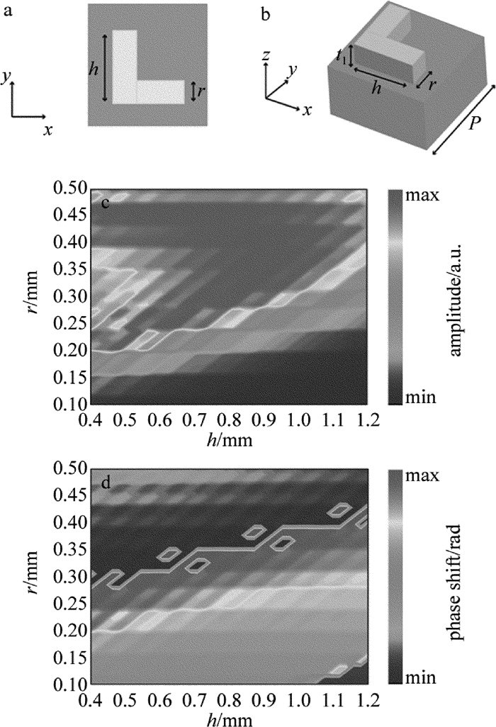
在实际制作过程中,张角和开口方向容易偏离设计值,导致功能实现率较低。而L型天线只有两个自由度(即臂长h和宽度r,如图 1所示)影响散射特性,以x线偏光入射时,α=90°,2β-α=0°,其散射表达式简化为:
Ei=12(Si+Ai)x±12(Si−Ai)y (2) 在制作过程中,不同臂长比较容易实现,因此使用L型天线作为基本电磁散射单元。
如图 1a和图 1b所示,单个散射结构单元周期长度为P=1.5mm,由上层L型金属天线(Au)和下层衬底材料组成聚丙烯组成,折射率在0.1THz时为1.48,L型天线厚度t1=300nm,大于太赫兹的趋肤深度。采用时域有限差分法(finite difference time-domain,FDTD)仿真软件进行模拟计算,在x, y, z方向设置为完全匹配层。计算了单个散射单元的电磁散射特性,即出射光的振幅和相位随不同臂长h和宽度r的变化行为,如图 1c和图 1d所示,其中入射光偏振方向为x方向线偏光。
根据图 1c和图 1d,可以获得不同(h, r)的出射光振幅和相位信息。根据设计超表面的基本原理,需要从中挑选出若干个不同(h, r)的天线来完成界面处不同相位突变的要求。为了实现2阶涡旋光束,首先挑选8个天线对2π相位突变进行覆盖,然后再挑选8个天线实现4π相位突变。
由图 1c和图 1d,首先选取4个天线出来,具体几何参量如图 2a所示。相邻天线相位差间隔为π/4,实现了一个相位差为π的覆盖。然后将A1~A4这4个天线逆时针旋转90°,形成A5~A8 4个基本天线,其相位差间隔也为π/4,而A4和A5的相位差也是π/4,从而完成另外一个π相位差覆盖。为了验证这8个天线是否实现了2π相位延迟,再次计算了它们的散射特性,如图 2b所示。可以明显看出,它们的相位延迟确实覆盖了2π,而且出射振幅比较平坦,符合超表面的设计原理。
对于4π相位突变而言,从阵列A中挑选出了A1,A3,A5和A7 4个天线单元,其相邻的相位差为π/2,这样这4个天线完成2π相位突变,因此可以再重复使用这4个天线就可以得到另一个2π相位突变。
2. L型天线阵列的研究
2.1 L型天线阵列的透射特性的研究
如前所述,光学超表面对入射光进行波前调制是基于界面处相位突变,根据广义斯涅耳定理[5],这种相位突变会带来异常折射或者异常反射。由于作者采用透射式结构来产生2阶太赫兹涡旋光束,因此,需要验证上述选取的天线阵列是否会产生异常折射现象。
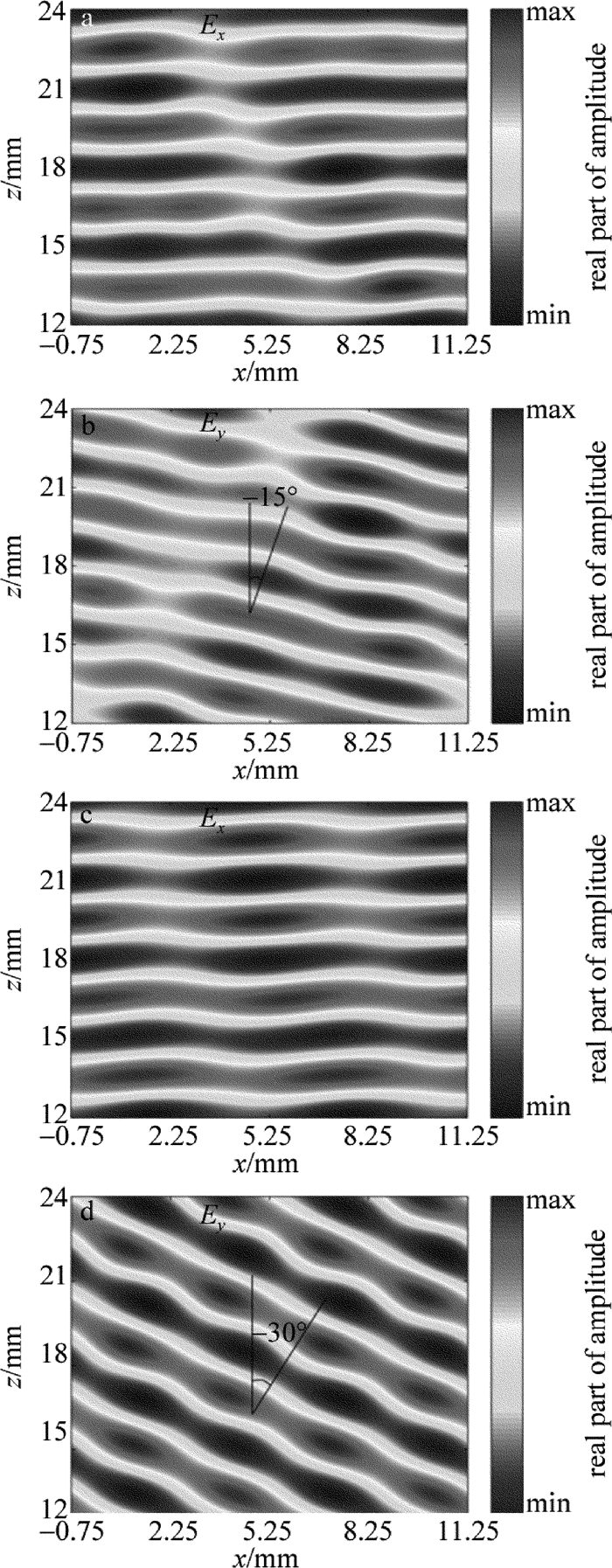
对于阵列A而言,入射光为x偏振0.1THz太赫兹波,光源是高斯光束[16],入射方向是z方向。图 3a显示出射光Ex分量没有被天线调制,属于正常透射光;而图 3b中,透射光Ey分量从阵列表面异常出射出去,计算数据显示其相位覆盖2π,形成异常折射现象,异常透射角约为-15°。理论上,根据广义斯涅耳定理可以计算异常折射角度θt′=arcsin(nisinθi-λ0/p),其中θi是入射角度,ni是衬底介质折射率,p是线性阵列周期长度,λ0是入射光波长。对于阵列A而言,θt′=-14.7°。
![Figure 3. a—the 1st order transmission spectrum parallel to the polarization direction of incident light b—the 1st order transmission spectrum perpendicular to the polarization direction of incident light c— the 2nd order transmission spectrum parallel to the polarization direction of incident light d—the 2nd order transmission spectrum perpendicular to the polarization direction of incident light]() Figure 3. a—the 1st order transmission spectrum parallel to the polarization direction of incident light b—the 1st order transmission spectrum perpendicular to the polarization direction of incident light c— the 2nd order transmission spectrum parallel to the polarization direction of incident light d—the 2nd order transmission spectrum perpendicular to the polarization direction of incident light
Figure 3. a—the 1st order transmission spectrum parallel to the polarization direction of incident light b—the 1st order transmission spectrum perpendicular to the polarization direction of incident light c— the 2nd order transmission spectrum parallel to the polarization direction of incident light d—the 2nd order transmission spectrum perpendicular to the polarization direction of incident light对于线性阵列B的透射特性如图 3b和图 3d所示。相同的入射条件,Ex和Ey分量的计算结果与阵列A大致趋势相同。由于线性阵列B实现的是4π相位突变,因此模拟计算的异常透射角约为-30°,广义斯涅耳定理计算结果为θt′=-30°。
分析1阶和2阶异常透射现象,Ex基本相同,而Ey分量,1阶的异常透射角度小于2阶异常透射角度,从上述公式可以看出,异常透射角是由介质折射率、入射角、入射光波长和周期长度决定,对比1阶和2阶计算条件,可以发现:唯一不同的是周期条件,2阶周期长度是1阶周期长度的2倍,进而影响异常折射角。
2.2 涡旋光产生相位板设计和分析
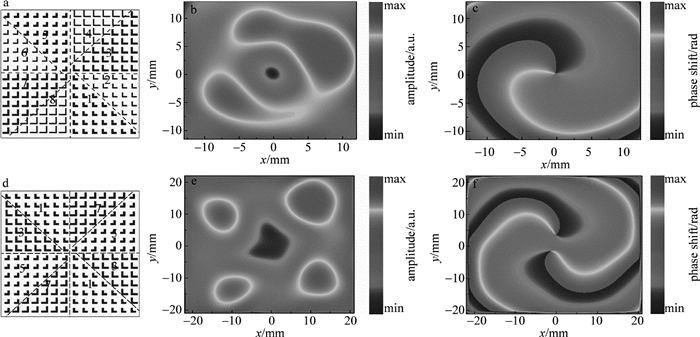
理论上涡旋光束的相位是由轨道角动量[17]exp(ilθ)因子确定,θ是相位角度,l是拓扑荷[18]。l=1时,在一个波长传播距离上,波前绕着中心旋转一周,相位改变2π。如图 4a所示,相位板面积为12mm×12mm,天线单元为14×14个。将整个相位板沿角向均匀分成8个象限,将阵列A中的天线A1~A8逆时针放置,相邻两个象限相位相差π/4。对于l=2时,相位改变4π,将阵列B中的天线A1~A8逆时针放置,相邻两个象限相位相差π/2,如图 4d所示。理论上增加象限或者天线密度可以提高转换效率。但是增加象限和天线密度后样品加工很难,另外相邻天线之间相互耦合程度会增加,使得相位突变会偏离原来设计要求。
![Figure 4. a—vortex phase plate under topological charge l=1 b—the normalized amplitude under topological charge l=1 c—the vortex phase under topological charge l=1 d—vortex phase plate under topological charge l=2 e—the normalized amplitude under topological charge l=2 f—the vortex phase under topological charge l=2]() Figure 4. a—vortex phase plate under topological charge l=1 b—the normalized amplitude under topological charge l=1 c—the vortex phase under topological charge l=1 d—vortex phase plate under topological charge l=2 e—the normalized amplitude under topological charge l=2 f—the vortex phase under topological charge l=2
Figure 4. a—vortex phase plate under topological charge l=1 b—the normalized amplitude under topological charge l=1 c—the vortex phase under topological charge l=1 d—vortex phase plate under topological charge l=2 e—the normalized amplitude under topological charge l=2 f—the vortex phase under topological charge l=2用0.1THz偏振光(x方向)入射到超表面阵列平面上,计算得到透射的涡旋光场分布和相位分布如图 4b、图 4c、图 4e、图 4f所示。图 4b、图 4e和图 4c、图 4f分别是l=1和l=2涡旋强度、相位分布示意图。由图 4b和图 4e可以看出光场中心点为暗场,即涡旋中心强度为0;图 4c和图 4f显示相位呈螺旋状。相比较于1阶光斑,2阶光斑的尺寸比1阶大,为了使光斑完整的呈现出来,所以采用的监视器尺寸也相应变大。注意到对于l=2涡旋光束相位分布的旋转中心发生分离,这是由于2阶光束阵列排列的非连续性造成的。
3. 结论
本文中提出了一种基于L型微天线,通过改变L型天线两个自由度的大小,使用8个天线实现相位覆盖0~2π和0~4π控制光波振幅相位的方法,0.1THz线偏光垂直入射,发现线性阵列的周期越小,其垂直偏振方向的异常透射角度越大,这点符合广义斯涅耳定理。另外还根据拓扑荷l为1和2,设计了1阶和2阶涡旋相位板,产生相应的涡旋光束。
-
Table 1 Deviation between FPGA and PC
coordinate of center absolute deviation visual studio (150.06907, 166.097) (0.06907, 0.097) FPGA (150.06881, 166.048) (0.06881, 0.048) Table 2 Processing time
FPGA visual studio proportion decomposition/μs 36.38 620 1/17.04 solving/μs 37.06 995 1/26.85 total/μs 73.44 1615 1/21.99 -
[1] FAN Ch L, LIU Ch, DING G, et al.A method of circle curve fitting based on the cumulative error of the radius error[C]//International Conference on Computational Intelligence and Security. New York, USA: IEEE, 2015: 211-214.
[2] WANG Q Q, LIU J, PENG Zh, et al.Measurement system for laser divergence angle based on LabView[J]. Chinese Journal of Lasers, 2012, 39(11):1108005(in Chinese). DOI: 10.3788/CJL
[3] ZHANG L. System of measuring laser spot[D]. Xi'an: Xidian University, 2010: 19-45(in Chinese).
[4] WANG L L, HU Zh W, JI H X. Laser spot center location algorithm based on Gaussian fitting[J]. Journal of Applied Optics, 2012, 33(5):985-990(in Chinese). http://d.old.wanfangdata.com.cn/Periodical/bjlgdxxb201602014
[5] LIU H L, HOU W, FAN Y L, et al. An improved algorithm of laser spot center location[J]. Computer Measurement & Control, 2014, 22(1):139-141(in Chinese). http://www.wanfangdata.com.cn/details/detail.do?_type=perio&id=CC029890225
[6] LAN Zh L, YANG X F. Practical improvement of laser spot center location algorithm[J]. Computer Engineering, 2008, 34(6):7-9(in Chinese). http://www.wanfangdata.com.cn/details/detail.do?_type=perio&id=jsjgc200806003
[7] NING Sh N, ZHU M, SUN H H, et al. Realization of improved sobel adaptive edge detection algorithm based on FPGA[J]. Chinese Journal of Liquid Crystals and Displays, 2014, 29(3):395-402(in Chinese). DOI: 10.3788/YJYXS
[8] SHI Y, CHENG X. Laser spot center detection based on the geometric feature[C]//International Symposium on Information Science & Engineering. New York, USA: IEEE, 2010: 322-325.
[9] LIU J S, YUAN S C. Subpixel location algorithm for circular targets center based on Zernike moments and curvature[J]. Computer Engineering & Applications, 2010, 46(29):153-156. http://d.old.wanfangdata.com.cn/Periodical/jsjgcyyy201029043
[10] ZHONG X J. Research on FPGA calculation method of typical matrix decomposition[D]. Harbin: Harbin Institute of Technology, 2012: 14-66(in Chinese).
[11] TAI Y G, LO C T D, PSARRIS K. Applying out-of-core QR decomposition algorithms on FPGA-based systems[C]//International Conference on Field Programmable Logic and Applications. New York, USA: IEEE, 2007: 86-91.
[12] HAN B, YANG Z, ZHENG Y R. FPGA implementation of QR decomposition for MIMO-OFDM using four CORDIC cores[C]//IEEE International Conference on Communications. New York, USA: IEEE, 2013: 4556-4560.
[13] WU G M, DOU Y, PETERSON G D. Blocking LU decomposition for FPGAs[C]//IEEE International Symposium on Field-Programmable Custom Computing Machines. New York, USA: IEEE, 2010: 109-112.
[14] TANG B P, JIANG Y H, ZHANG X Ch. Feature extraction method of rolling bearing fault based on singular value decomposition-morphology filter and empirical mode decomposition[J]. Chinese Journal of Mechanical Engineering, 2010, 46(5):37-42(in Chinese). DOI: 10.3901/JME.2010.05.037
[15] WU G M, DOU Y, WANG M. A fine-grained parallel algorithm for the Cholesky decomposition[J]. Computer Engineering & Science, 2010, 32(9):102-106(in Chinese). http://www.wanfangdata.com.cn/details/detail.do?_type=perio&id=jsjgcykx201009027
[16] GUO L, TANG Y H, ZHOU J, et al. Research on parallel architecture for LDLT decomposition -processor[J]. Computer Engineering, 2011, 37(21):241-243(in Chinese).


 下载:
下载:

