
Multi-profile images synthesis detection method for laser dressing of forming grinding wheels
-
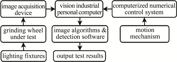
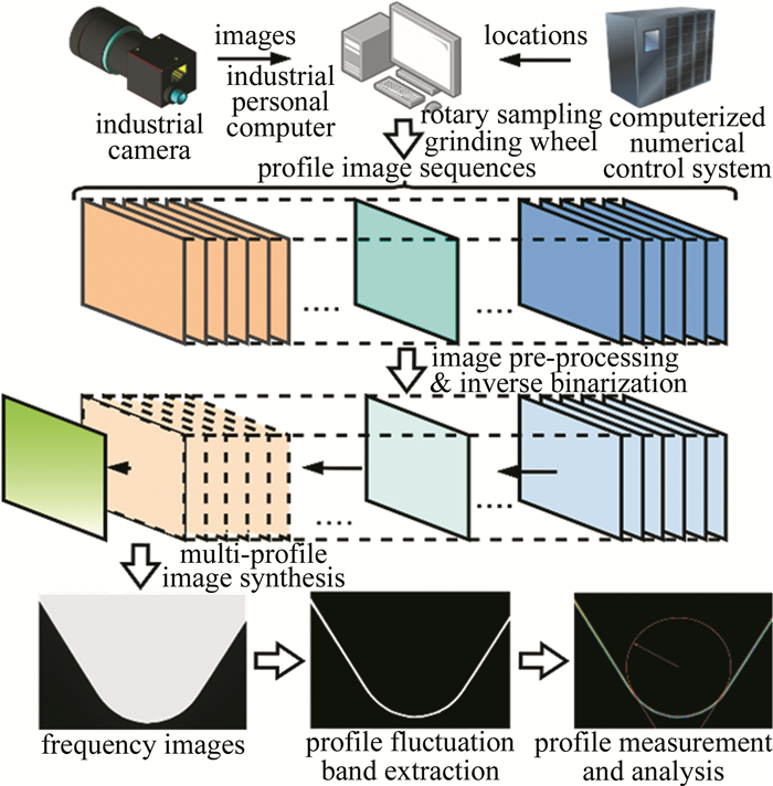
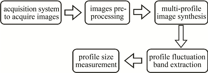
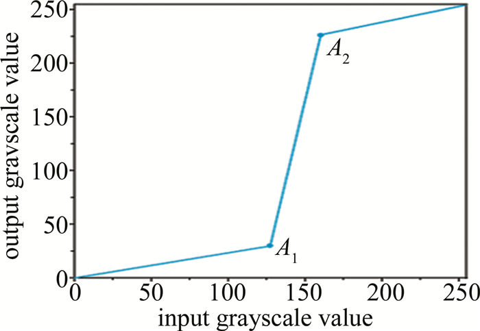
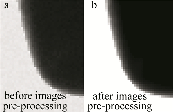
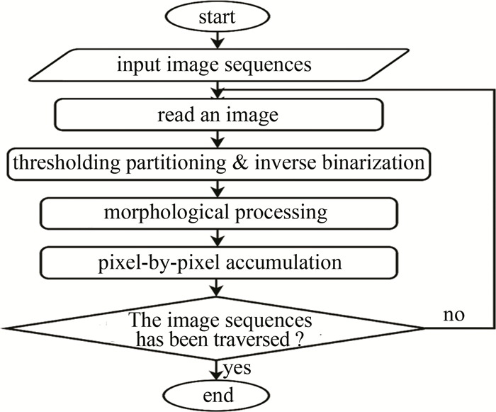
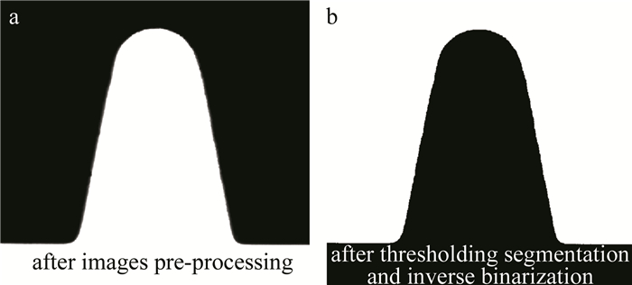
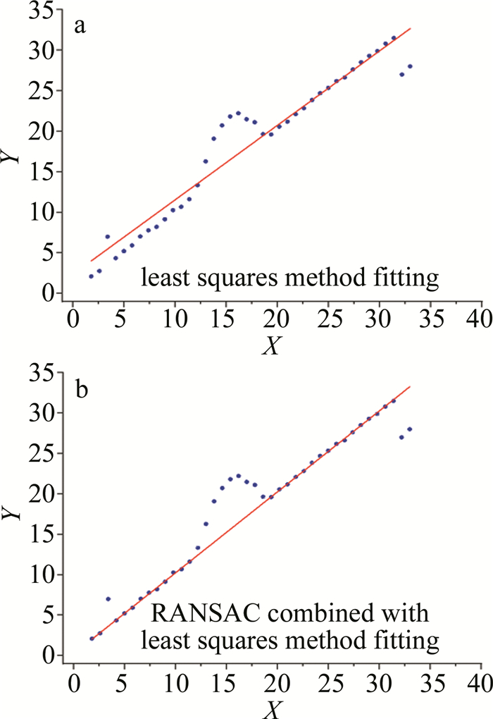
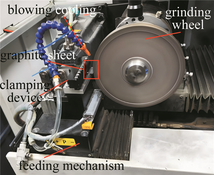
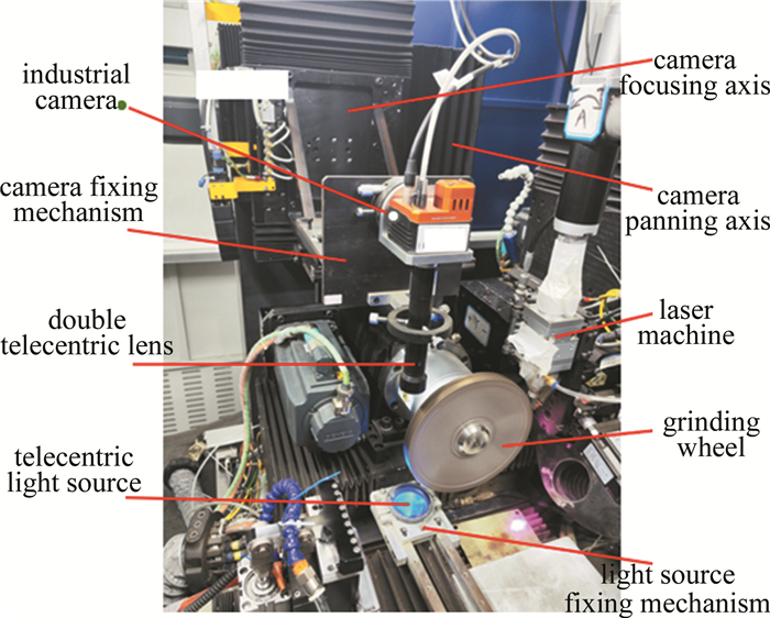
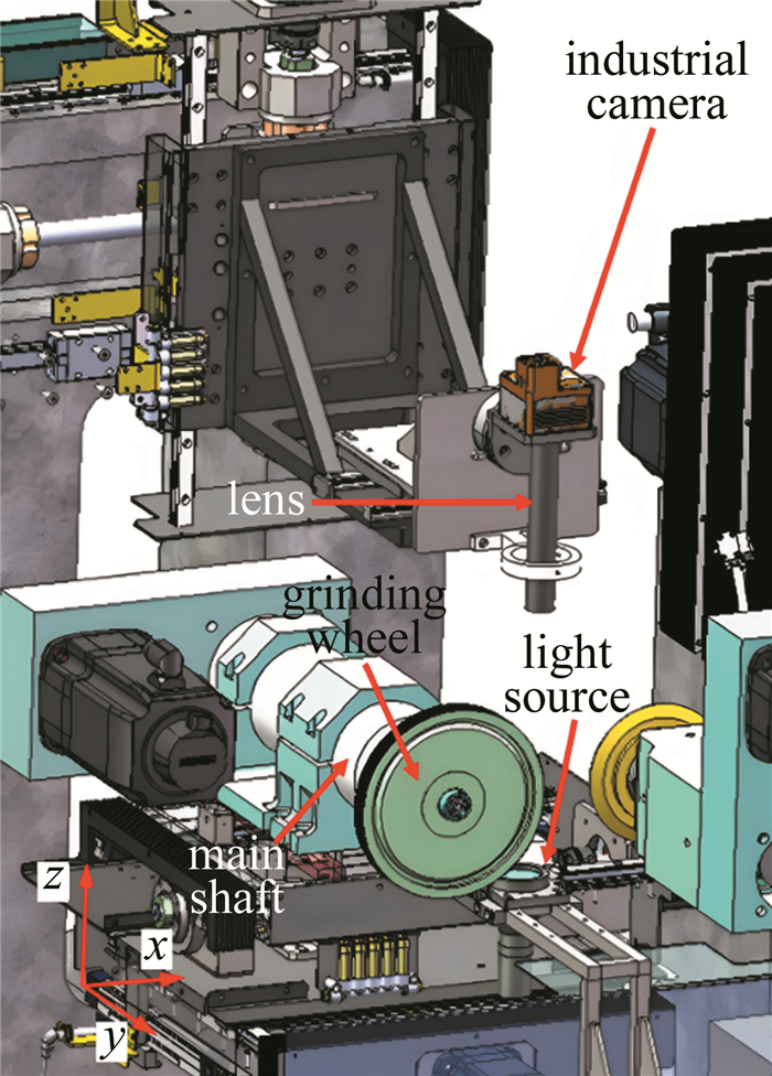
摘要: 为了解决复杂轮廓成形砂轮激光修整过程中在线检测难、轮廓检测精度低、速度慢等问题, 搭建了一套基于砂轮激光修整机床的图像采集系统, 提出了一种多轮廓图像合成检测方法, 定义了轮廓波动带的概念。首先利用引导滤波和灰度变换预处理砂轮轮廓图像, 增强轮廓特征; 再使用全局阈值分割和反二值化得到二值图像, 将二值图像序列合成为带有像素频率信息的轮廓频率图像, 通过阈值分割提取出轮廓波动带; 最后使用随机抽样一致算法结合最小二乘法对波动带最外侧的边缘点集进行拟合, 完成直线和圆弧特征的检测。结果表明, 该检测方法与单一截面视觉检测法相比, 检测效率接近, 但误差范围缩小了66.67%;与磨削复映检测法相比, 检测结果存在一个固定偏差, 平均误差在7 μm左右, 但检测效率提高了91.67%。该方法能高精度、高效地检测成形砂轮轮廓, 为成形砂轮轮廓检测方法提供了新思路。Abstract: To solve the problems of complex online inspection, low accuracy, and slow speed of profile inspection during laser dressing of complex profile forming grinding wheels, a set of image acquisition systems based on laser dressing grinding wheel machine tool was built, and a multi-profile image synthesis detection method was proposed, which defined the concept of profile wave band. Firstly, the guided filter and grayscale transformation were used to preprocess the grinding wheel profile image to enhance the features of the grinding wheel profile, and then the binary image was obtained by global thresholding segmentation and inverse binarization, and then the binary image sequence was synthesized into a profile frequency image with pixel frequency information, and the profile wave band was extracted by thresholding segmentation. Finally, the random sample consensus algorithm combined with the least squares method was used to fit the outermost edge point set of the wave band to complete the detection of straight line and circular arc features. The results show that the detection efficiency of the detection method is similar to that of the single-section visual inspection method, but the error range is reduced by 66.67%. Compared with the grinding remapping detection method, there is a fixed deviation in the inspection results, with an average error of about 7 μm, but the detection efficiency is increased by 91.67%. This method can detect the profile of the forming wheel with high precision and efficiency, which provides a new idea for the profile detection method of the forming grinding wheel.
-
0. 引言
对某些材料沿一定方向施加电场时,材料折射率会受到外加电场的影响,而且折射率的大小还与电场方向有关,导致从这些材料透射的光偏振态发生改变,产生电光效应。通常把电光材料的折射率正比于外加电场强度的电光效应称为线性电光效应,或Pockels效应。具有电光效应的磷酸二氢钾和铌酸锂等电光晶体在光电子技术领域有着广泛应用,如制成电光调制器[1-2]、电光开关[3-5]、电光逻辑器[6]、可调滤波器[7]和量子器件[8]等性能优异的光电器件,另外还可用于测量强电场[9-10]以及高电压[11-12]等电学参量。特别是随着新型电力系统的发展,要求输电容量、传输电压和电流越来越大,以及智能化越来越高,传统电压互感器已不能满足。而利用电光效应制成的新型光学电压互感器[13-15]具有体积小、集成度高、抗电磁干扰、绝缘性好和动态范围大等优点,解决了传统电压互感器存在的容易燃烧爆炸、绝缘性能差和频带窄等问题,在电力系统的过电压测量与在线监测中有着重要的应用。目前报道的光学电压互感器基本上只用于测量电压值的大小[11-16],几乎没有对电压的方向进行测量。然而,通过电压值及其方向才能全面准确反映电压变化。因此,作为一个重要的电压特性参量,电压方向也需要测量。为实现光学电压互感器测量电压的方向,本文作者研究了利用Pockels电光效应对电压方向进行测量的原理,并进行了实验测试。
1. 测量原理
考虑电光材料为磷酸二氢钾(KH2PO4, KDP)晶体,其折射率与晶体的空间坐标x、y和z轴方向有关,x轴和y轴方向的主折射率都为no,z轴方向的主折射率为ne,其线性电光系数γij矩阵可用下式表示[17-18]:
[γij]=[000000000γ41000γ52000γ63] (1) 式中:i=1, …, 6;j=1, 2, 3。这类晶体的电光张量元素只有γ41、γ52、和γ63不为零,其余元素都为零。
无外电场作用时,晶体折射率在空间各个方向的取值分布可用以z轴为对称轴的椭球方程表示为:
x2no2+y2no2+z2ne2=1 (2) 若电场沿晶体的z轴方向施加,则z轴方向的电场强度大小为Ez,x和y轴方向的电场强度都为零。根据Pockels电光效应[17],这时折射率椭球方程变为:
(1no2+γ63Ez)x′2+(1no2−γ63Ez)y′2+1ne2z′2=1 (3) 式中: x′、y′、z′为感应主轴坐标系。
考虑入射线偏振光沿z轴方向传播,其光矢量Ep的振动方向沿晶体的x轴方向,如图 1所示。
令z′=0,式(3)变为:
(1n02+γ63Ez)x′2+(1n02−γ63Ez)y′2=1 (4) 由式(4)可得电光晶体在感应主轴x′和y′方向的折射率分别为:
nx′=no−12no3γ63Ez (5) ny′=no+12no3γ63Ez (6) 入射线偏振光进入晶体后, 其光矢量Ep沿x′和y′方向分解为两个垂直的偏振分量Ep, x′和Ep, y′,其中Ep, x′=A1cos(ωt),Ep, y′=A2cos(ωt),A1和A2分别为光矢量在x′和y′方向的振幅,ω为光矢量振动频率,t为传播时间。经过晶体长度为L的光程分别为nx′L和ny′L,则相应的相位延迟分别为:
\varphi_{x^{\prime}}=\frac{2 {\rm{ \mathsf{ π}}}}{\lambda} n_{x^{\prime}} L=\frac{2 {\rm{ \mathsf{ π}}} L}{\lambda}\left(n_o-\frac{1}{2} n_o{ }^3 \gamma_{63} E_z\right) (7) \varphi_{y^{\prime}}=\frac{2 {\rm{ \mathsf{ π}}}}{\lambda} n_{y^{\prime}} L=\frac{2 {\rm{ \mathsf{ π}}} L}{\lambda}\left(n_o+\frac{1}{2} n_{\mathrm{o}}{ }^3 \gamma_{63} E_z\right) (8) 式中:λ为入射光的波长。Ep, x′和Ep, y′通过电光晶体后会产生一个相位差:
\Delta \varphi=\varphi_{y^{\prime}}-\varphi_{x^{\prime}}=\frac{2 {\rm{ \mathsf{ π}}}}{\lambda} n_{\mathrm{o}}{ }^3 \gamma_{63} E_z L=\frac{2 {\rm{ \mathsf{ π}}}}{\lambda} n_{\mathrm{o}}{ }^3 \gamma_{63} U (9) 式中:U=EzL是沿z轴方向施加的电压。式(9)说明由于两个偏振分量Ep, x′和Ep, y′之间存在相位延迟,将会改变透射光束的偏振态。由偏振光理论可知,在一般情况下,这时通过晶体后的两偏振分量合成为一束椭圆偏振光,合成振动公式表示为[17-18]:
\frac{E_{\mathrm{p}, x^{\prime}}{ }^2}{A_1{ }^2}+\frac{E_{\mathrm{p}, y^{\prime}}{ }^2}{A_2{ }^2}-\frac{2 E_{\mathrm{p}, x^{\prime}} E_{\mathrm{p}, y^{\prime}}}{A_1 A_2} \cos (\Delta \varphi)=\sin ^2(\Delta \varphi) (10) 若施加的电压U方向沿光传播方向,且U值在(0,Vπ)范围,Vπ是电光晶体的半波电压,根据式(9)和式(10)可得相应相位差Δφ的值在(0,π),上述通过电光晶体合成的椭圆偏振光表现为右旋;同理,若U方向与光传播方向相反,相应的Δφ为(-π,0),合成的椭圆偏振光则表现为左旋[18-19]。
由上述分析可知,通过电光晶体的光偏振态取决于施加的电压方向。下一步需要确定椭圆偏振光的光矢量的旋转轨迹,可把λ/4波片置于椭圆偏振光传播前面,如图 2所示。调节λ/4波片的快轴与椭圆偏振光的长轴方向一致,慢轴则和短轴方向一致,使椭圆偏振光的长短轴产生一个π/2的附加相位。右旋椭圆偏振光的长短轴方向的相位差Δφ1=π/2,透过λ/4波片后的相位差变成Δφ=Δφ1+π/2=π,根据式(10)可知,右旋椭圆偏振光变换为线偏振光,其偏振方向在空间坐标的二、四象限;同理,对于左旋椭圆偏振光,其长短轴方向的相位差Δφ2=-π/2,透过λ/4波片后的相位差变成Δφ=Δφ2+π/2=0,变换为线偏振光[18, 20],其偏振方向在一、三象限。因此,可以通过测量电光晶体的透射椭圆偏振光的光矢量旋转方向,然后根据偏振光合成理论和电光效应判断出外加电压的方向,实现利用电光效应测量电压的方向。
![图 2 判断椭圆偏振光旋转方向的原理图]() 图 2 判断椭圆偏振光旋转方向的原理图Figure 2. Schematic diagram of judging the rotation direction of elliptically polarized light
图 2 判断椭圆偏振光旋转方向的原理图Figure 2. Schematic diagram of judging the rotation direction of elliptically polarized light2. 测量装置及结果分析
根据上述理论分析,采用信息光电子综合实验仪(CA9005)搭建电压方向测量装置,如图 3所示。半导体激光器发射波长为635 nm的激光沿电光晶体的z轴方向传播,依次通过起偏器、电光晶体、检偏器和光探测器,另外在实验过程中还需加入λ/4波片,各光学元件调至等高共轴。沿电光晶体的z轴方向施加一定大小的电压U。电光晶体无电压作用时,从起偏器透射的光通过电光晶体后其偏振方向保持不变,由于检偏器与起偏器正交,无光输出,测量光强为零。
![图 3 利用电光效应测量电压方向的示意图]() 图 3 利用电光效应测量电压方向的示意图Figure 3. Experimental device of measuring voltage direction based on electro-optic effect
图 3 利用电光效应测量电压方向的示意图Figure 3. Experimental device of measuring voltage direction based on electro-optic effect设置施加的电压U=100 V,且电压方向沿光传播方向,即在图 3中电压方向表现为从左指向右(左正右负),这时检偏器有光输出。以z轴为中心旋转检偏器角度,每旋转10°用探测器测量对应的光功率,旋转一周,得到通过电光晶体的透射光的归一化功率随x-y坐标平面空间角度不同的分布,如图 4所示。迎着光观测,图 4中透射光在空间不同角度的功率大小分布呈现出椭圆形状,说明其光矢量的大小和方向都发生改变,功率在空间位置约20°出现最大值,归一化功率接近1,最小值则在空间位置约110°时为0.65,末端轨迹表现为椭圆。因此,透射光是椭圆偏振光,其长轴位于空间角度20°处,短轴位于空间角度110°处。
![图 4 电压方向指向右时光通过电光晶体的功率分布]() 图 4 电压方向指向右时光通过电光晶体的功率分布Figure 4. Intensity distribution of light through electro-optic crystal for the voltage to the right
图 4 电压方向指向右时光通过电光晶体的功率分布Figure 4. Intensity distribution of light through electro-optic crystal for the voltage to the right为进一步判断图 4中椭圆偏振光的光矢量旋转方向是右旋还是左旋,在图 3中的电光晶体和检偏器之间加入λ/4波片,并且调节λ/4波片的快轴与椭圆偏振光的长轴方向相同,其慢轴则与短轴方向一致,类似上述操作方法旋转检偏器测量光功率,得到透射椭圆偏振光透过λ/4波片后的归一化功率随x-y坐标平面空间角度不同的分布,如图 5所示。迎着光观测,图 5中的功率分布呈现出“8”字形状,在空间100°处达到一个最大值,归一化功率为1;在空间190°处存在一个最小值,归一化功率为0.24,接近于零,相当于消光。另外,这两个角度相差90°。这是典型的线偏振光通过检偏器的光强变化[21]。说明从电光晶体透射的椭圆偏振光再通过λ/4波片后变换成线偏振光,而且线偏振光的偏振方向位于x-y坐标二、四象限。根据前面的理论分析可知,此时通过电光晶体的椭圆偏振光表现为右旋,施加的电压方向与光传播方向相同,实验与理论相符。
![图 5 电压方向指向右时椭圆偏振光通过λ/4波片的功率分布]() 图 5 电压方向指向右时椭圆偏振光通过λ/4波片的功率分布Figure 5. Intensity distribution of elliptically polarized light through λ/4 wave-plate for the voltage to the right
图 5 电压方向指向右时椭圆偏振光通过λ/4波片的功率分布Figure 5. Intensity distribution of elliptically polarized light through λ/4 wave-plate for the voltage to the right参考上述实验方法,改变施加电压U的方向,使其与光传播方向相反,即在图 3中电压方向表现为从右指向左(左负右正),测量得到通过电光晶体的透射光的归一化功率随x-y坐标平面空间角度不同的分布,如图 6所示。与图 4结果类似,透射光是椭圆偏振光,但其长短轴方向不一样,长轴位于空间角度约130°,短轴位于空间角度约40°。加入λ/4波片后,测得透射椭圆偏振光通过λ/4波片后的归一化功率随x-y坐标平面空间角度不同的分布,如图 7所示。同样与图 4结果类似,功率分布呈现“8”字形状,功率最大值出现在空间位置约34°,最小值则在约124°。说明通过λ/4波片后光为线偏振光,其偏振方向位于x-y坐标一、三象限,相应的椭圆偏振光是左旋,施加的电压方向与光传播方向相反。这进一步验证了利用Pockels电光效应测量电压方向的方法是有效的。
![图 6 电压方向指向左时光通过电光晶体的功率分布]() 图 6 电压方向指向左时光通过电光晶体的功率分布Figure 6. Intensity distribution of light through electro-optic crystal for the voltage to the left
图 6 电压方向指向左时光通过电光晶体的功率分布Figure 6. Intensity distribution of light through electro-optic crystal for the voltage to the left![图 7 电压方向指向左时椭圆偏振光通过λ/4波片的功率分布]() 图 7 电压方向指向左时椭圆偏振光通过λ/4波片的功率分布Figure 7. Intensity distribution of elliptically polarized light through λ/4 wave-plate for the voltage to the left
图 7 电压方向指向左时椭圆偏振光通过λ/4波片的功率分布Figure 7. Intensity distribution of elliptically polarized light through λ/4 wave-plate for the voltage to the left限于仪器条件和安全考虑,作者缺少更高电压的方向测量实验。然而由式(9)和式(10)可知,当光源和电光晶体确定后,电光效应导致的光偏振分量的相位差Δφ与外加电压U成单值函数,即相位差大小取决于外加电压,U越大,Δφ越大。只要施加的电压不高于半波电压,Δφ的取值仍在(0,π)或(-π,0)之间,相应电光效应的透射光偏振态变化能被上述方法测出。其中半波电压是电光晶体的一个重要参数,由入射光波长和电光晶体本身决定[17-18],通常可达千伏以上。由此推断: 采用上述方法测量更高电压的方向也是可行的, 适用于新型的光学电压互感器。
3. 结论
本文作者结合偏振光理论和不同方向电压作用下的电致旋光特性,提出了一种利用Pockels电光效应测量电压方向的方法,并进行了实验测量。实验结果与理论相符,表明可以通过测量沿一定方向的施加电压作用下,光从电光晶体透射的偏振态变化,然后根据光偏振态与电压方向的关系确定施加电压的方向。迎着光观测,当透射的椭圆偏振光表现为右旋时,施加电压的方向沿光传播方向;当透射的椭圆偏振光表现为左旋时,电压方向则与光传播方向相反。这一工作有助于进一步理解电光效应中施加电压方向、光传播方向和光的偏振态三者之间的相互关系,对设计既能测量电压大小、又能判断其方向的光学电压互感器提供一定的指导作用,在光电子器件中具有重要的应用价值。
-
![]()
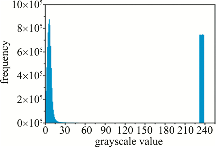
图 9 阈值分割和反二值化效果
Figure 9. Effects of thresholding segmentation and inverse binarization
![]()
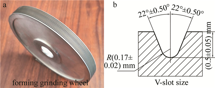
图 16 凹V型轮廓成形砂轮实物及尺寸情况
Figure 16. Concave V-slot forming grinding wheel and dimensional situation
表 1 V型槽角度D检测结果
Table 1 Detection results of V-slot angle D
the number of V-slot the multi-profile images synthesis detection method/mm the single-section visual detection method/mm the grinding remapping detection method/mm 1 44.213 44.156 44.281 2 44.087 43.915 44.042 3 44.245 44.323 44.203 4 44.076 44.031 44.109 5 44.070 44.264 44.115 6 44.208 44.344 44.293 7 44.168 44.199 44.156 8 44.092 43.984 44.067  下载: 导出CSV
表 2 V型槽深度H检测结果
Table 2 Detection results of V-slot depth H
the number of V-slot the multi-profile images synthesis detection method/mm the single-section visual detection method/mm the grinding remapping detection method/mm 1 0.5251 0.5274 0.5183 2 0.5294 0.5396 0.5206 3 0.5342 0.5362 0.5299 4 0.5297 0.5373 0.5222 5 0.5300 0.5450 0.5255 6 0.525 0.5338 0.5177 7 0.5229 0.5287 0.5197 8 0.5281 0.5471 0.5207
下载: 导出CSV
表 3 槽底圆弧半径R检测结果
Table 3 Detection results of V-slot bottom arc radius R
the number of V-slot the multi-profile images synthesis detection method/mm the single-section visual detection method/mm the grinding remapping detection method/mm 1 0.1664 0.1611 0.1749 2 0.1624 0.1492 0.1686 3 0.1586 0.161 0.1672 4 0.1621 0.1566 0.1729 5 0.1597 0.1584 0.1671 6 0.1638 0.1571 0.1717 7 0.1662 0.1623 0.1706 8 0.1642 0.1528 0.1712
下载: 导出CSV
表 4 检测效率
Table 4 Detection efficiency
the multi-profile images synthesis detection method the single-section visual detection method the grinding remapping detection method time spent/s 30 20 360
下载: 导出CSV
表 5 检测误差
Table 5 Detection errors
detection features detection methods the number of V-slot 1 2 3 4 5 6 7 8 angel/(°) the single-section visual detection method -0.265 -0.157 0.16 0.122 0.169 0.071 0.043 -0.203 the multi-profile images synthesis detection method -0.082 0.065 0.091 -0.033 -0.105 -0.085 0.012 0.025 depth/mm the single-section visual detection method 0.0091 0.019 0.0063 0.0151 0.0195 0.0161 0.009 0.0264 the multi-profile images synthesis detection method 0.0068 0.0088 0.0043 0.0075 0.0045 0.0073 0.0032 0.0074 radius/mm the single-section visual detection method -0.0138 -0.0194 -0.0062 -0.0163 -0.0087 -0.0146 -0.0083 -0.0184 the multi-profile images synthesis detection method -0.0085 -0.0062 -0.0086 -0.0108 -0.0074 -0.0079 -0.0044 -0.007
下载: 导出CSV
表 6 检测误差的统计指标
Table 6 Statistical indicators of the detection errors
detection features statistical indicators the multi-profile images synthesis detection method the single- section visual detection method mean value/mm -0.0076 -0.0132 radius range/mm 0.0064 0.0132 variance 3.0925×10⁻⁶ 2.13×10⁻⁵ mean value/mm 0.0062 0.01506 depth range/mm 0.0056 0.0201 variance 3.36937×10⁻⁶ 3.92×10⁻⁵
下载: 导出CSV
-
[1] 王龙, 汪刘应, 刘顾, 等. 成型砂轮磨削齿轮的运动学模型构建与齿轮精度分析[J]. 制造技术与机床, 2019(12): 112-116. https://www.cnki.com.cn/Article/CJFDTOTAL-ZJYC201912037.htm WANG L, WANG L Y, LIU G, et al. Kinematic model construction and gear precision analysis of gear machined by form grinding[J]. Manufacturing Technology & Machine Tool, 2019(12): 112-116(in Chinese). https://www.cnki.com.cn/Article/CJFDTOTAL-ZJYC201912037.htm
[2] 王昊. 金刚石成形砂轮视觉检测精度分析与视觉系统改进研究[D]. 长沙: 湖南大学, 2020: 1-55. WANG H. Precision analysis of diamond wheel visual detection and improvement research of visual system[D]. Changsha: Hunan University, 2020: 1-55(in Chinese).
[3] 邓辉, 朱鹏程, 王林青, 等. 砂轮表面测量方法研究进展[J]. 机械科学与技术, 2020, 39(4): 599-607. https://www.cnki.com.cn/Article/CJFDTOTAL-JXKX202004016.htm DENG H, ZHU P Ch, WANG L Q, et al. Research progress in measurement methods of grinding wheel surface[J]. Mechanical Science and Technology for Aerospace Engineering, 2020, 39(4): 599-607(in Chinese). https://www.cnki.com.cn/Article/CJFDTOTAL-JXKX202004016.htm
[4] 彭檐波, 陈根余, 周聪, 等. 基于图像处理的成形砂轮激光切向整形系统算法与实现[J]. 应用激光, 2018, 38(3): 454-460. https://www.cnki.com.cn/Article/CJFDTOTAL-YYJG201803022.htm PENG Y B, CHEN G Y, ZHOU C, et al. Algorithm and implementation of laser tangential shaping grinding wheel system based on image processing[J]. Applied Laser, 2018, 38(3): 454-460(in Chin-ese). https://www.cnki.com.cn/Article/CJFDTOTAL-YYJG201803022.htm
[5] 彭檐波. 基于机器视觉的激光切向整形V形凹面砂轮测控系统设计[D]. 长沙: 湖南大学, 2018: 1-67. PENG Y B. Design of measuring and controlling system for laser tangential shaping of V-shaped concave grinding wheels based on machine vision[D]. Changsha: Hunan University, 2018: 1-67(in Chin-ese).
[6] 类志杰. 基于机器视觉的凸圆弧砂轮边缘检测及定位技术研究[D]. 长沙: 湖南大学, 2019: 1-66. LEI Zh J. Research on edge detection and positioning technology of convex arc grinding wheel based on machine vision[D]. Changsha: Hunan University, 2019: 1-66(in Chinese).
[7] 牛牧, 许黎明, 赵达, 等. 基于工件轮廓图像的砂轮磨损在线检测方法[J]. 上海交通大学学报, 2021, 55(3): 221-228. https://www.cnki.com.cn/Article/CJFDTOTAL-SHJT202103001.htm NIU M, XU L M, ZHAO D, et al. Workpiece-contour-image based wheel wear online detection methodology[J]. Journal of Shanghai Jiao Tong University, 2021, 55(3): 221-228(in Chinese). https://www.cnki.com.cn/Article/CJFDTOTAL-SHJT202103001.htm
[8] 牛牧. 曲线磨削砂轮修整方法和修整工艺的研究[D]. 上海: 上海交通大学, 2020: 1-96. NIU M. Research on dressing method and dressing process of profile grinding wheel[D]. Shanghai: Shanghai Jiao Tong University, 2020: 1-96(in Chinese).
[9] 母德强, 郑金涛, 司苏美, 等. 基于激光三角法的砂轮磨损量检测[J]. 长春工业大学学报, 2021, 42(3): 200-204. https://www.cnki.com.cn/Article/CJFDTOTAL-JLGX202103002.htm MU D Q, ZHENG J T, SI S M, et al. Research on wear measurement of grinding wheel based on laser triangulation[J]. Journal of Changchun University of Technology, 2021, 42(3): 200-204 (in Chin-ese). https://www.cnki.com.cn/Article/CJFDTOTAL-JLGX202103002.htm
[10] 郑金涛. 磨床砂轮磨损量与表面轮廓检测技术研究[D]. 长春: 长春工业大学, 2021: 1-47. ZHENG J T. Research on measurement technology of grinding wheel wear and surface profile for grinding machine[D]. Changchun: Changchun University of Technology, 2021: 1-47(in Chinese).
[11] 周炼, 安晨辉, 侯晶, 等. 圆弧金刚石砂轮三维几何形貌的在位检测和误差评价[J]. 光学精密工程, 2017, 25(12): 3079-3088. https://www.cnki.com.cn/Article/CJFDTOTAL-GXJM201712014.htm ZHOU L, AN Ch H, HOU J, et al. 3D geometric topographic mea-surement and error evaluation of arc diamond wheel[J]. Optics and Precision Engineering, 2017, 25(12): 3079-3088 (in Chinese). https://www.cnki.com.cn/Article/CJFDTOTAL-GXJM201712014.htm
[12] 师超钰, 朱建辉, 孙冠男, 等. 成形磨砂轮圆弧廓形关键参数在位检测方法及试验研究[J]. 中国测试, 2021, 47(3): 36-42. https://www.cnki.com.cn/Article/CJFDTOTAL-SYCS202103006.htm SHI Ch Y, ZHU J H, SUN G N, et al. In-situ measuring method and experimental research on key circular-arc profile parameters of form grinding wheel[J]. China Measurement & Test, 2021, 47(3): 36-42(in Chinese). https://www.cnki.com.cn/Article/CJFDTOTAL-SYCS202103006.htm
[13] 邵升阳. 基于数字图像处理的砂轮磨损检测系统及方法研究[D]. 厦门: 厦门大学, 2020: 1-62. SHAO Sh Y. Research on grinding wheel wear detection system and method based on digital image processing[D]. Xiamen: Xiamen University, 2020: 1-62(in Chinese).
[14] XU L M, XU K Z, CHAI Y D. Identification of grinding wheel wear signature by a wavelet packet decomposition method[J]. Journal of Shanghai Jiao Tong University (Science Edition), 2010, 15(3): 323-328.
[15] 胡一星. 基于全局图像的轮廓曲线磨削加工误差动态检测与补偿[D]. 上海: 上海交通大学, 2018: 1-57. HU Y X. Global image based online error detection and compensation of profile grinding[D]. Shanghai: Shanghai Jiao Tong University, 2018: 1-57(in Chinese).
[16] 胡一星, 范帆, 许黎明, 等. 砂轮廓形原位视觉检测方法与试验研究[J]. 机械制造, 2018, 56(5): 80-82. https://www.cnki.com.cn/Article/CJFDTOTAL-JXZG201805032.htm HU Y X, FAN F, XU L M, et al. In-situ visual detection method and experimental research of the abrasive profile[J]. Machinery, 2018, 56(5): 80-82 (in Chinese). https://www.cnki.com.cn/Article/CJFDTOTAL-JXZG201805032.htm
[17] LI T Y, QIU Z J, TANG J J. Research on measurement method of grinding wheel profile based on image mosaic[J]. Measurement Science and Technology, 2019, 31(3): 035402.
[18] 李天一. 基于机器视觉的砂轮轮廓测量方法的研究[D]. 天津: 天津大学, 2019: 1-76. LI T Y. Research on grinding wheel profile measurement based on machine vision[D]. Tianjin: Tianjin University, 2019: 1-76(in Chinese).
[19] 郭佩瑜, 张宝华. 基于引导滤波和模糊算法的红外背景抑制算法[J]. 激光技术, 2018, 42(6): 854-858. DOI: 10.7510/jgjs.issn.1001-3806.2018.06.024 GUO P Y, ZHANG B H. Infrared background suppression algorithm based on guided filtering and fuzzy algorithm[J]. Laser Technology, 2018, 42(6): 854-858(in Chinese). DOI: 10.7510/jgjs.issn.1001-3806.2018.06.024
[20] 王浩, 张叶, 沈宏海, 等. 图像增强算法综述[J]. 中国光学, 2017, 10(4): 438-448. https://www.cnki.com.cn/Article/CJFDTOTAL-ZGGA201704005.htm WANG H, ZHANG Y, SHEN H H, et al. Review of image enhancement algorithms[J]. Chinese Optics, 2017, 10(4): 438-448(in Chinese). https://www.cnki.com.cn/Article/CJFDTOTAL-ZGGA201704005.htm
[21] 蔡旭明, 李笑, 刘玉县, 等. 基于灰度直方图的激光光斑中心定位算法[J]. 激光技术, 2023, 47(2): 273-279. DOI: 10.7510/jgjs.issn.1001-3806.2023.02.018 CAI X M, LI X, LIU Y X, et al. Laser spot center location algorithm based on gray histogram[J]. Laser Technology, 2023, 47(2): 273-279 (in Chinese). DOI: 10.7510/jgjs.issn.1001-3806.2023.02.018
[22] 吴一全, 孟天亮, 吴诗婳. 图像阈值分割方法研究进展20年(1994—2014)[J]. 数据采集与处理, 2015, 30(1): 1-23. https://www.cnki.com.cn/Article/CJFDTOTAL-SJCJ201501001.htm WU Y Q, MENG T L, WU Sh H. Research progress of image thresholding methods in recent 20 years(1994-2014)[J]. Journal of Data Acquisition and Processing, 2015, 30(1): 1-23(in Chinese). https://www.cnki.com.cn/Article/CJFDTOTAL-SJCJ201501001.htm
[23] 张伟杰, 刘立君, 张红兴. 基于图像形态学激光模具裂纹修复技术研究[J]. 激光技术, 2016, 40(2): 189-194. DOI: 10.7510/jgjs.issn.1001-3806.2016.02.008 ZHNAG W J, LIU L J, ZHANG H X. Repair techniques of dies with laser based on image morphological processing[J]. Laser Technology, 2016, 40(2): 189-194 (in Chinese). DOI: 10.7510/jgjs.issn.1001-3806.2016.02.008
[24] 袁清珂, 张振亚, 毕庆. 改进RANSAC算法在直线拟合中的应用[J]. 组合机床与自动化加工技术, 2015(1): 123-125. https://www.cnki.com.cn/Article/CJFDTOTAL-ZHJC201501035.htm YUAN Q K, ZHANG Zh Y, BI Q. Linear fitting application based on the improved RANSAC algorithm[J]. Modular Machine Tool & Automatic Manufacturing Technique, 2015(1): 123-125(in Ch-inese). https://www.cnki.com.cn/Article/CJFDTOTAL-ZHJC201501035.htm
-
期刊类型引用(1)
1. 张艳,马春明,刘树东,孙叶美. 基于多尺度特征增强的高效Transformer语义分割网络. 光电工程. 2024(12): 87-102 .  百度学术
百度学术
其他类型引用(0)


计量
- 文章访问数: 6
- HTML全文浏览量: 0
- PDF下载量: 5
- 被引次数: 1