
Research on image segmentation and color recognition method of laser weld
-
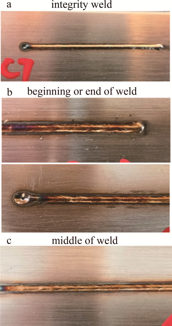
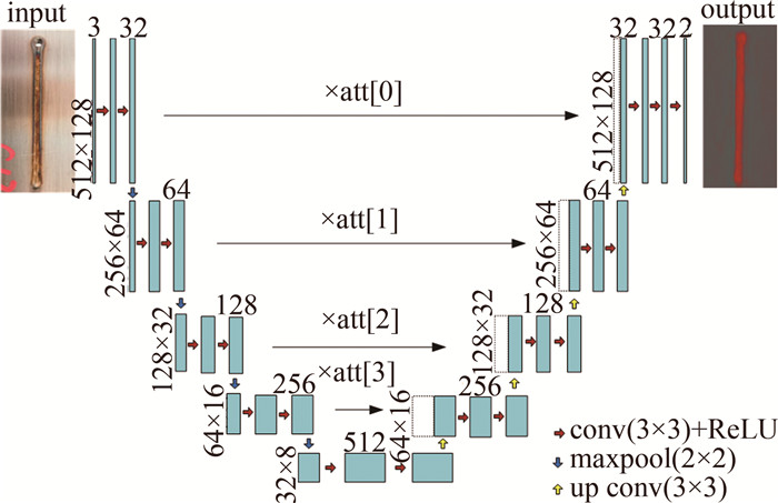
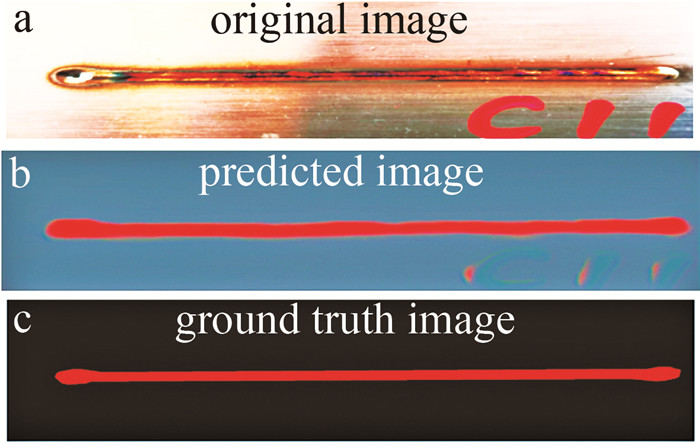
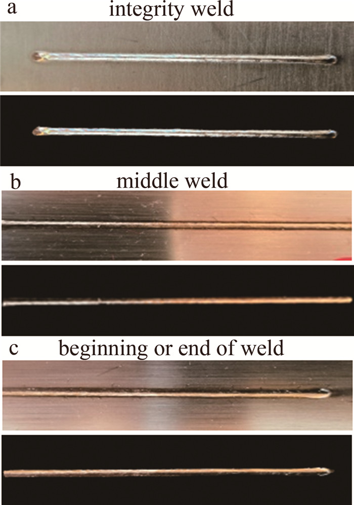
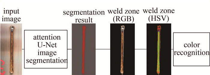
摘要: 为了减少激光焊缝语义分割中焊缝形状和颜色多样性对分割精度的影响,采用注意力机制的图像语义分割方法提取焊缝区域。通过把焊缝区域图像从RGB转变到HSV颜色空间,在HSV模型空间实现对焊缝表面颜色识别,分析了3种类型焊缝对区域分割和颜色识别的影响。结果表明,焊缝分割区域平均像素精度约为91.2%,添加注意力机制U型网络模型的分割效果更好。此焊缝表面颜色自动识别结果符合生产要求,在工业生产中有广泛应用前景。Abstract: In order to reduce the influence of weld shape and color diversity on segmentation accuracy in laser weld semantic segmentation, an image semantic segmentation method based on attention mechanism was used to extract weld. The image in the weld was converted from RGB(red, green, blue) to HSV(hue, saturation, value) color space, and the weld surface color was recognized in HSV. The effects of three kinds of welds on region segmentation and color recognition were analyzed. The results show that the average pixel accuracy of the weld segmentation region is about 91.2%, and the segmentation effect of the attention U-Net model with attention mechanism is better. The results of automatic identification of weld surface color meet production requirements, and have broad application prospects in industrial production.
-
Keywords:
- image processing /
- semantic segmentation /
- color recognition /
- deep learning /
- attention mechanism
-
引言
不锈钢以其轻、寿命长、耐磨性高、低成本、易加工等优势,被广泛应用于航空航天等重大装备制造中,特别是在地铁车顶盖的应用[1-2]。由于地铁用不锈钢材料厚度较薄(不大于1mm),因此在激光焊接过程中,难以较好地控制焊接工艺,常常会出现焊穿的技术问题[3-4]。对此,本文中以地铁用不锈钢薄板材料为研究对象,探究不同工艺参量对熔宽、熔深的影响规律,这对实现地铁安全运行具有重要的作用。
当前,许多学者对不锈钢的焊接工艺进行了广泛的研究,如LIU等人以厚度为16mm的SUS301L奥氏体不锈钢板为实验材料,采用X射线衍射对激光焊和熔化极金属活性气体(metal active gas,MAG)弧形焊的焊接接头进行了测试分析[5]。HARISH等人研究了3mm厚激光切割的AISI 304奥氏体不锈钢薄板的激光焊接性[6]。TIAN采用工业机器人对专用于轨道列车的SUS301L不锈钢进行了搭接焊和对接焊激光自熔焊试验研究[7]。CHEN等人对4mm和2mm SUS301L不锈钢开展了激光对接焊研究,并对焊接接头进行了详细分析[8]。虽然这些研究为不锈钢激光焊接提供理论依据,但是上述研究者主要是对厚板及焊后试样焊缝区化学成分进行深入分析,对SUS301L薄板(不大于1mm)不锈钢激光叠焊过程中的研究鲜有报道。因此,针对地铁车顶SUS301L不锈钢叠焊工艺中对熔宽、熔深的技术需求,开展SUS301L不锈钢叠焊工艺参量优化显得尤为重要。
本文中首先采用Simufact Welding有限元软件对0.6mm厚SUS301L不锈钢薄板非熔透型激光焊接工艺参量(激光功率、焊接速率、保护气体流量、离焦量)对熔宽、熔深的显著影响进行了初步评价,讨论各工艺参量对熔宽、熔深的影响规律。其次,基于有限元分析结果,确定正交试验参量的取值范围,在满足熔宽、熔深的技术指标条件下,对工艺参量进行正交优化。最后,在最优工艺条件下开展焊接试样的力学性能分析,验证了本仿真及试样参量的合理性,为地铁车顶用SUS301L不锈钢激光焊接提供理论指导与工艺设计参考。
1. 数值模拟仿真
采用Simufact Welding软件,对焊接过程进行仿真,分析激光功率、焊接速率对上板熔宽和下板熔深的影响规律[9]。仿真模拟过程中设定环境温度及试件温度为20℃,将SUS301L不锈钢材料看作均匀且各向同性。模型尺寸与试件大小一致为120mm×60mm,为了保证计算速度和准确率,划分网格时采用过渡网格,设置焊接区长度范围20mm,采用0.625mm×0.625mm致密网格,非焊接区域则采用2mm×2mm网格。两区域间过渡区域长度4mm,以0.5mm为间距等距划分,网格划分效果如图 1所示。
1.1 激光功率对熔深、熔宽的影响
图 2为焊接速率为38mm/s、离焦量为0mm、激光功率范围为950W~1150W时,下板熔深、上板熔宽的变化折线图。由图 2分析可知,激光功率和上板熔深、下板熔宽呈正相关,且激光功率对熔深的影响更为显著。激光功率在该区间内,上板均完全焊透,且激光功率为1150W时,下板焊透处于临界状态,因此激光功率在950W~1150W为合适区间。
1.2 焊接速率对熔深、熔宽的影响
从图 3中看出,激光功率为1050W、离焦量为0mm时,焊接速率从36mm/s增加到40mm/s的过程中,下板熔深、上板熔宽的变化与焊接速率呈负相关。由于焊接速率增大,导致热量衰减速度增大,焊缝背面温度降低,熔池最高温度也降低,因此上板熔宽和下板的熔深对应呈现下降的趋势。焊接速率为36mm/s时,下板熔深占比超99%,几近焊透,因此焊接速率在36mm/s~40mm/s为合适区域。
由焊接过程仿真模拟,初步确定了合理的焊接工艺参量范围:激光功率为950W~1150W、焊接速率为36mm/s~38mm/s,为之后的试验提供理论参量。
2. 试验材料与方法
试验中采用的材料为SUS301L奥氏体不锈钢,上下板厚均为0.6mm,牌号:022Cr17Ni7,抗拉强度大于820MPa,屈服强度大于480MPa,试样尺寸大小为60mm×120mm,相关物理参量如表 1所示。
Table 1. Related physical parameters of SUS301L austenitic stainless steelboiling point/℃ melting point/℃ latent heat of phase change/(J·kg-1) density/(kg·m-3) Poisson’s ratio 3073 1447 2.6×10⁵ 7800 0.3 试验中采用IPG公司的光纤激光器。焊接试验分成两部分,首先采用单一因素实验,研究不同激光焊接工艺参量(保护气体流量、离焦量、激光功率、焊接速率)对截面处焊缝熔深熔宽的影响;然后通过正交试验优化焊接工艺参量对使用优化后焊接工艺参量的焊件进行宏观形貌与微观组织的观测, 并进行力学性能的分析。
3. 试验结果与分析
3.1 保护气体流量对熔深、熔宽的影响
保护气体流量的选择会影响到激光焊接的质量,过多的保护气不仅造成了浪费,而且会带走焊接过程中很大一部分的能量,直接降低焊接效率;相反,过少的保护气,无法有效地将工件上方聚集的等离体子及时吹走[10]。采用单一变量法,保护气体采用氩气,取工艺参量为:激光功率1150W、焊接速率38mm/s、离焦量0mm,由于此功率参量下所有试件均焊透,因此用束腰宽代替原本下板熔深数据。图 4为3种不同保护气体流量上板熔宽及束腰宽度。
由图 4可知,随着氩气流量的增大,单位时间内热量损失增加,焊件从激光中得到的热量不断减少,上板熔宽呈递减趋势。焊缝束腰宽度在保护气体流量为25L/min时数值最小,呈V字型变化。
3.2 离焦量对熔深、熔宽的影响
薄板的焊接通常为正离焦。进行负离焦焊接时,下板容易被焊透从而在焊缝背部的中间位置形成凸起,在地铁车顶上应用时,影响外观[11]。本文中取零离焦时,焊缝完整且连续,没有咬边、凹陷、变形等明显缺陷。因此在本小节试验中,离焦量分别取0mm, +1mm, +2mm, 其余焊接工艺参量为:激光功率1150W,焊接速率38mm/s,保护气体流量25L/min。图 5为3种不同离焦量下上板熔宽及下板熔深。
由图 5分析可知,离焦量增加的过程中,下板熔深随之减小,上板熔宽有所下降但是变化不大,结合图中数据分析得出: 离焦量对焊缝熔深的影响略大于熔宽。
3.3 焊接速率对熔深、熔宽的影响
焊接速率大小通常负相关于焊缝熔深,影响焊纹密度,热输入量的合理配置能够很好地规避焊缝不连续等缺陷,保证焊接质量[12]。在激光功率1050W、离焦量0mm、保护气体流量25L/min下,焊接速率分别取为36mm/s, 38mm/s, 40mm/s。图 6为3种不同速率下上板熔宽及下板熔深。
由图 6可知,焊接速率与上板熔宽和下板熔深呈负相关性。在36mm/s的焊接速率下,下板熔深占比超过98%,焊件几近焊穿,处于临界状态。在3种速率下,焊缝形貌都良好,深度达到要求,下板均为焊透。
3.4 激光功率对熔深、熔宽的影响
激光功率过小,焊件可能会无法焊透,焊缝过窄,影响到接头力学性能;激光功率过大,热量的迅速吸收造成温度梯度的增大,在焊件内部会存在较大的残余应力,导致焊件的变形[13-14]。取焊接工艺参量为:焊接速率36mm/s、离焦量0mm、保护气体流量25L/min,激光功率大小分别为950W, 1050W, 1150W。图 7为3种不同激光功率下焊缝熔深、熔宽数据变化图。
由图 7可知,随着激光功率的增加,作用在焊件上的功率密度逐渐增大,工件获得能量增多,上板往下传递的热量随之增加,焊缝熔深熔宽也逐渐增大。当功率增大到1150W之后,下板焊透。
3.5 正交试验优化焊接工艺参量
由单因素实验结果可确定焊接工艺参量范围:激光功率950W~1050W,焊接速率36mm/s~40mm/s,离焦量0mm~2mm,保护气体流量20L/min~30L/min。正交试验共4个因素,每个因素均为3个水平,如表 2所示。以三水平四因素正交表设计正交试验,如表 3所示。表 3中实验结果为上板熔宽以及下板熔深占比。
Table 2. Orthogonal test factors and level tablefactor laser power A/W welding speed B/(mm·s-1) defocusing amout C/mm shielding gas flow D/(L·min-1) level 1 950 36 0 20 level 2 1050 38 1 25 level 3 1150 40 2 30 Table 3. Orthogonal test tableexperimentnumber factor A factor B factor C factor D result 1 result 2 laser power/W welding speed/(mm·s-1) defocusing amout/mm shielding gas flow/(L·min-1) upper plate welding width/μm percentage of lower plate welding depth/% 1 1 1 1 1 1204.7 42.38 2 1 2 2 2 1208.2 27.72 3 1 3 3 3 968.8 0.00 4 2 1 2 3 1298.9 100.00 5 2 2 3 1 1247.9 26.98 6 2 3 1 2 1217.0 81.57 7 3 1 3 2 1333.2 100 8 3 2 1 3 1327.0 100 9 3 3 2 1 1292.8 100 对上板熔宽以及下板熔深制正交分析表,分析得出结果为:激光功率对上板熔深和下板熔宽影响最大,离焦量对下板熔深影响更加明显,而焊接速率对上板熔宽影响明显,保护气体流量影响最小。最优工艺参量水平为A2B1C2D2, 即激光功率1050W,焊接速率36mm/s,离焦量1mm,保护气体流量25L/min。
3.6 仿真与试验结果对比
激光焊接功率1050W、焊接速率36mm/s、离焦量1mm、保护气体流量25L/min时,仿真与试验焊缝界面重叠对比如图 8所示。从图 8中看出,焊缝上表面几乎完全重合,包括焊缝中央凸起的部分,二者的熔宽、熔深数据基本一致,实验下板焊缝熔深略大于仿真结果, 两个焊缝截面图的轮廓变化趋势也基本保持一致。综上所述,仿真结果十分接近于实验结果,SUS301L不锈钢的激光焊接仿真对于实际焊接过程有指导意义。
4. 焊缝形貌与性能分析
用正交优化后得到的工艺参量进行焊接实验,对所得焊缝进行宏观检测、金相分析以及力学性能检测。
4.1 焊缝形貌
图 9为焊接完成后焊缝整体形貌图。焊缝形貌连续无扭曲,整体为银白色,无气孔、裂纹及咬边等常见缺陷。
4.2 焊缝微观组织及金相分析
焊缝整体形貌如图 10所示。呈钉子状,上板焊缝熔宽1216.4μm,下板焊缝熔深407.4μm,焊缝深宽比较大。周围熔合线明显,过渡处圆滑,无气孔等明显缺陷。上板有余高但余量不大,有助于提高焊缝强度。
由图 11可以看出,焊缝中心处生长方向性明显的晶粒为等轴晶,晶粒细小,从焊缝中轴向两边生长。焊接完成后熔池内的液态金属冷却并凝固,焊缝中心处温度梯度不断下降,焊缝区内的合金元素产生偏析,提升了溶质浓度,使得焊缝中心处的结晶速率加快。晶核生长环境趋同,因此, 焊缝中心处的晶粒会转变为等轴晶而非柱状晶。
图 12为焊缝底部及边缘微观组织。可以看出, 焊缝底部与焊缝边缘的组织生长方向垂直于熔合线法线方向,焊缝靠近熔合线处的组织,基本都是柱状晶,这是由于焊缝与熔合线周围的焊缝组织在经历过较大的温度梯度后,结晶速率会减慢,有利于柱状晶的形成。而靠近热影响区的晶粒生长过程中呈无向型且出现回复或者二次结晶,这就导致晶粒会粗化[15-16]。粗化大小会随着与熔合线距离的增大而减小。
4.3 焊缝力学性能分析
4.3.1 焊缝显微硬度
以焊缝中轴为对称线,测试两边母材、熔合区以及中心处的各点显微硬度。图 13为打点示意图,图 14和图 15为测试结果。
由图 14可以看出, 母材处平均显微硬度为520HV,硬度最高; 其次为热影响区,平均硬度为330HV; 焊缝处的硬度最低,平均硬度为215HV。在图 15中,纵向平均显微硬度大小220HV,折线变化不大,说明焊缝中轴纵向上硬度分布均匀。
4.3.2 焊缝拉剪性能
采用Instron5985拉伸设备,机器拉力范围为0kN~250kN,拉伸速率范围为0mm/min~1430mm/min。为保证试验数据准确与合理性,取3组试验的平均拉剪力大小作为结果。试验中测得3次拉剪力大小分别为2524.98N, 2435.36N, 2719.26N,平均拉剪力大小2559.96N。拉力变化曲线如图 16所示。
同等材料下,采用点焊方式,最小剪切拉伸载荷为1912N,平均拉伸载荷为2256N。试验中测得数据与平均值数据均大于上述数值,说明采用激光焊接所得的SUS301L不锈钢焊接接头在拉剪强度上达到了预期要求。
5. 结论
对SUS301L奥氏体不锈钢0.6mm+0.6mm叠焊进行了非熔透型激光焊接模拟仿真及试验研究。
(1) 通过Simufact Welding有限元方法对SUS301L不锈钢进行叠焊数值模拟,得到有效工艺参量范围为:激光功率950W~1050W, 焊接速率36mm/s~40mm/s, 离焦量0mm~2mm, 保护气体流量20L/min~30L/min。
(2) 在单因素试验的基础上进行正交试验,发现对上板焊缝熔宽和对下板焊缝熔深影响最大的因素均为激光功率,而离焦量和焊接速率分别对下板熔深和上板熔宽影响较大。通过正交优化获得了最优工艺参量为:激光功率1050W,焊接速速36mm/s,离焦量1mm,保护气体流量25L/min。
(3) 在最优工艺参量下,试件焊缝表面呈银白色,焊缝连续且完整,焊缝区的晶粒多为等轴晶与柱状晶。焊缝区显微硬度低于热影响区,同样也低于母材。焊缝平均拉剪载荷为2559.96N,焊缝强度达到要求。
-
表 1 3种焊缝的dice系数值
Table 1 Dice values of three welds
model integrity
weld/%middle
weld/%beginning or
end of weld/%attention U-Net 95.91 94.93 93.2 U-Net 94.2 91.5 94.9  下载: 导出CSV
表 2 焊缝区域H、S和V的计算值
Table 2 Calculated values of H, S and V in the weld zone
H/(°) S V attention
U-NetU-Net attention
U-NetU-Net attention
U-NetU-Net integrity weld 49 50 32 32 189 191 middle weld 14 14 103 112 179 163 beginning or
end of weld14 14 101 100 154 158
下载: 导出CSV
-
[1] LI H. Analysis and control of laser weld crack[C]//2020 3rd International Conference on Electron Device and Mechanical Engineering (ICEDME). New York, USA: IEEE, 2020: 192-195.
[2] LI X, XIE J, ZHOU Y. Effects of oxygen contamination in the argon shielding gas in laser welding of commercially pure titanium thin sheet[J]. Journal of Materials Science, 2005, 40(13): 3437-3443. DOI: 10.1007/s10853-005-0447-8
[3] HARWIG D D, FOUNTAIN C, ITTIWATTANA W, et al. Oxygen equivalent effects on the mechanical properties of titanium welds[J]. Welding Journal Research Supplement, 2000, 79(11): 305s-316s.
[4] 樊立民, 耿乃涛, 杨柳, 等. 钛合金焊接过程防氧化保护技术进展[J]. 钢铁钒钛, 2021, 42(6): 43-50. https://www.cnki.com.cn/Article/CJFDTOTAL-GTFT202106005.htm FAN L M, GENG N T, YANG L, et al. Progress of anti-oxidation protection technology in titanium alloy welding process[J]. Iron Steel Vanadium Titanium, 2021, 42(6): 43-50(in Chinese). https://www.cnki.com.cn/Article/CJFDTOTAL-GTFT202106005.htm
[5] GUPTA S S, KWON T H, KIM K D. Color based image processing techniques to detect oxide film during welding[C]//2020 International Conference on Electronics, Information, and Communication (ICEIC). New York, USA: IEEE, 2020: 1-4.
[6] HUA S, LI B, SHU L, et al. Defect detection method using laser vision with model-based segmentation for laser brazing welds on car body surface[J]. Measurement, 2021, 178: 109370. DOI: 10.1016/j.measurement.2021.109370
[7] 齐继阳, 李金燕, 陆震云, 等. 改进的Otsu法在焊接图像分割中的应用[J]. 焊接学报, 2016, 37(10): 97-100. https://www.cnki.com.cn/Article/CJFDTOTAL-HJXB201610024.htm QI J Y, LI J Y, LU Zh Y, et al. Application of improved Otsu algorithm to welding image segmentation[J]. Transaction of the China Welding Institution, 2016, 37(10): 97-100(in Chinese). https://www.cnki.com.cn/Article/CJFDTOTAL-HJXB201610024.htm
[8] MALARVEL M, SETHUMADHAVAN G, BHAGI P C R, et al. An improved version of Otsu's method for segmentation of weld defects on X-radiography images[J]. Optik, 2017, 142: 109-118. DOI: 10.1016/j.ijleo.2017.05.066
[9] 戴漩领, 茅云生, 周永清. 基于改进分水岭的焊缝分割算法[J]. 船舶工程, 2021, 43(s1): 428-433. https://www.cnki.com.cn/Article/CJFDTOTAL-CANB2021S1094.htm DAI X L, MAO Y Sh, ZHOU Y Q. Weld segmentation algorithm based on improved watershed[J]. Ship Engineer, 2021, 43(s1): 428-433(in Chinese). https://www.cnki.com.cn/Article/CJFDTOTAL-CANB2021S1094.htm
[10] ANAND R S, KUMAR P. Flaw detection in radiographic weldment images using morphological watershed segmentation technique[J]. NDT & E International, 2009, 42(1): 2-8.
[11] RADI D, ABO-ELSOUD M E A, KHALIFA F. Accurate segmentation of weld defects with horizontal shapes[J]. NDT & E International, 2022, 126: 102599.
[12] XU H, YAN Z H, JI B W, et al. Defect detection in welding radiographic images based on semantic segmentation methods[J]. Measurement, 2022, 188: 110569. DOI: 10.1016/j.measurement.2021.110569
[13] GOLODOV V A, MALOSTEVA A A. Approach to weld segmentation and defect classification in radiographic images of pipe welds[J]. NDT & E International, 2022, 127: 102597.
[14] 常颖, 常大俊. 改进型卷积神经网络焊点缺陷识别算法研究[J]. 激光技术, 2020, 44(6): 779-783. DOI: 10.7510/jgjs.issn.1001-3806.2020.06.023 CHANG Y, CHANG D J. Research on solder joint defect recognition algorithm based on improved convolutional neural network[J]. Laser Technology, 2020, 44(6): 779-783. DOI: 10.7510/jgjs.issn.1001-3806.2020.06.023
[15] RONNEBERGER O, FISCHER P, BROX T. U-net: Convolutional networks for biomedical image segmentation[C]//International Conference on Medical Image Computing and Computer-assisted Intervention. Munich, Germany: Springer, 2015: 234-241.
[16] 吴量, 付殿臣, 程超. 基于Unet的多注意力脑肿瘤图像分割算法[J]. 计算机技术与发展, 2021, 31(12): 85-91. https://www.cnki.com.cn/Article/CJFDTOTAL-WJFZ202112015.htm WU L, FU D Ch, CHENG Ch. Multi-attention brain tumor image segmentation algorithm based on Unet[J]. Computer Technology and Development, 2021, 31(12): 85-91(in Chinese). https://www.cnki.com.cn/Article/CJFDTOTAL-WJFZ202112015.htm
[17] SCHLEMPER J, OKTAY O, SCHAAP M, et al. Attention gated networks: Learning to leverage salient regions in medical images[J]. Medical Image Analysis, 2019, 53: 197-207.
[18] 李代林, 万杰, 朱化凤, 等. 基于HSV颜色空间的水下物体识别技术研究[J]. 中国科学: 物理学力学天文学, 2015, 45(8): 71-75. https://www.cnki.com.cn/Article/CJFDTOTAL-JGXK201508010.htm LI D L, WAN J, ZHU H F, et al. Underwater image recognition technology research based on HSV color space[J]. Scientia Sinca Physica, Mechanica & Astronomica, 2015, 45(8): 71-75(in Chin-ese). https://www.cnki.com.cn/Article/CJFDTOTAL-JGXK201508010.htm
[19] ZHONG H, WANG R. A visual-degradation-inspired model with HSV color-encoding for contour detection[J]. Journal of Neuroscience Methods, 2021, 369: 109423.
[20] CHERNOV V, ALANDER J, BOCHKO V. Integer-based accurate conversion between RGB and HSV color spaces[J]. Computers & Electrical Engineering, 2015, 46: 328-337.
[21] 张强, 李嘉锋, 卓力. 基于卷积神经网络的监控场景下车辆颜色识别[J]. 测控技术, 2017, 36(10): 11-14. https://www.cnki.com.cn/Article/CJFDTOTAL-IKJS201710004.htm ZHANG Q, LI J F, ZHUO L. Vehicle color recognition using convolutional neural network for urban surveillance images[J]. Measurement and Control Technology, 2017, 36(10): 11-14(in Chinese). https://www.cnki.com.cn/Article/CJFDTOTAL-IKJS201710004.htm
[22] 周欣, 刘硕迪, 潘薇, 等. 自然交通场景中的车辆颜色识别[J]. 计算机科学, 2021, 48(s1): 15-20. https://www.cnki.com.cn/Article/CJFDTOTAL-JSJA2021S1003.htm ZHOU X, LIU Sh D, PAN W, et al. Vehicle color recognition in natural traffic scene[J]. Computer Science, 2021, 48(s1): 15-20(in Chinese). https://www.cnki.com.cn/Article/CJFDTOTAL-JSJA2021S1003.htm
[23] BARGSHADY G, ZHOU X, DEO R C, et al. The modeling of human facial pain intensity based on Temporal Convolutional Networks trained with video frames in HSV color space[J]. Applied Soft Computing, 2020, 97: 106805.
[24] SHELHAMER E, LONG J, DARRELL T. Fully convolutional networks for semantic segmentation[J]. IEEE Transactions on Pattern Analysis and Machine Intelligence, 2017, 39(4): 640-651.
[25] CHEN L Ch, PAPANDREOU G, KOKKINOS I, et al. DeepLab: Semantic image segmentation with deep convolutional nets, atrous convolution, and fully connected CRFs[J]. IEEE Transactions on Pattern Analysis and Machine Intelligence, 2018, 40(4): 834-848.
-
期刊类型引用(1)
1. 刘向玲,任勇,王璐. 基于U-Net与GAN的低照度激光雷达图像缺失区域补全算法. 激光杂志. 2025(01): 135-141 .  百度学术
百度学术
其他类型引用(1)


计量
- 文章访问数: 9
- HTML全文浏览量: 0
- PDF下载量: 5
- 被引次数: 2