
Research on electro-directional infrared target pointing error optimization technology
-
摘要: 为了提高电致定向型红外靶标在挂载飞行过程中动态指向精度,在硬件限制的位置信息更新频率难以提高的条件下,提出了卡尔曼滤波算法对靶标的位置信息进行预测从而提升更新速率的解决方案,利用全球定位系统和惯性导航系统的数据,建立了基于飞行速度、姿态和位置信息采样频率等因素的动态指向误差模型,并进行了理论分析和实验验证。结果表明,对红外靶标系统在匀速直线飞行过程中将位置采样率由5 Hz提升至10 Hz时,指向角误差减小了54.66%。此研究基于现有条件,为减小定向辐射型红外靶标动态指向误差提供了一种有益的尝试。Abstract: In order to improve the dynamic pointing accuracy of electro-directional infrared targets during mount flight, under the condition that the the update frequency of position information is difficult to increase due to the hardware limit, a solution for the Kalman filter algorithm was proposed to predict the position information of the target and to increase the update rate. The model of dynamic pointing error based on factors such as flight speed, attitude, and sampling frequency of position information is established. Theoretical analysis and experimental verification were carried out. The results show that when the position sampling rate of the infrared target system is increased from 5 Hz to 10 Hz during the uniform linear flight, the pointing angle error is reduced by 54.66%. This study provides a useful attempt to reduce the dynamic pointing error of directional radiative infrared targets based on existing conditions.
-
Keywords:
- sensor technique /
- pointing accuracy /
- Kalman filter algorithm /
- infrared target
-
引言
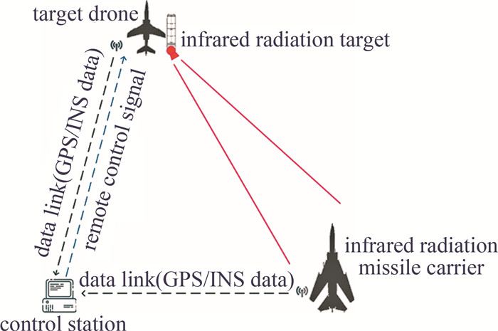
电致定向辐射型靶标[1]是一种可在自主对抗条件下,动态模拟目标红外特性的机载红外靶标[2]。其根据靶试过程中双方态势(速度、距离、相对位置、姿态)的变化,通过指向系统使红外辐射束始终覆盖被测试系统,并根据双方的相对位置,调节红外辐射强度,从而完成目标动态红外特性模拟的过程,为相关系统的研制及训练奠定技术基础。
动态指向是新型红外靶标的关键技术,其动态指向精度直接决定了靶试过程中靶标所产生的红外辐射信号是否能准确地覆盖被测试导引头[3]。目前该功能主要通过地面控制站完成计算处理,并通过无线数据链上传至靶标完成控制。该过程受数据链通信速率、位置数据更新速率、处理时延、指向平台响应时间及靶标搭载平台飞行状态[4]等因素的影响,从而导致在实际飞行过程中,系统的指向方向与被测试目标相对于系统的实际方向存在误差。现阶段主要通过增大红外辐射发散角以提高系统对指向误差的容限,但过大的红外辐射发散角势必会影响系统输出红外辐射的强度范围,因此,研究动态指向过程中各因素对指向误差的影响成为该领域亟待解决的问题。本文作者针对红外靶标指向系统存在误差问题建立了动态指向模型,并仿真飞行状态,分析得出位置更新频率是重要影响原因,通过挂载飞行数据实验显示,使用卡尔曼滤波算法对靶标位置信息进行预测的方法可以有效减小指向角度误差。
1. 靶标动态指向过程
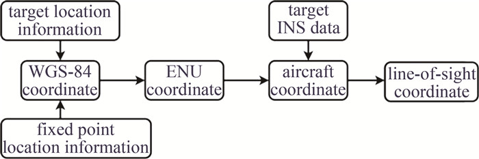
动态红外靶标系统的工作流程如图 1所示。其过程与空间激光通信系统[5]中捕获、跟踪和瞄准(acquisition,tracking,pointing,ATP)对准过程类似:靶标控制站根据靶标载机与目标(导弹载机)的全球定位系统(global positioning system,GPS)位置信息计算双方的相对位置关系[6],并根据靶机惯性导航系统(inertial navigation system,INS)信息完成靶标指向角度的解算,遥控靶标两轴指向平台动作,从而实现飞行过程中动态指向功能。
具体的解算过程如图 2所示。靶机及目标的位置数据为通过GPS获得大地坐标系下的经纬度及高度,上述数据通过4次坐标转换[7],将双方的相对关系转换至载机坐标下,最后通过极坐标投影过程,完成靶标两轴指向角度的解算。
![图 2 靶标指向坐标系变换示意图]() 图 2 靶标指向坐标系变换示意图Figure 2. Schematic of a target pointing to a coordinate system transformation
图 2 靶标指向坐标系变换示意图Figure 2. Schematic of a target pointing to a coordinate system transformation(1) 由大地坐标转换至1984年世界大地测量系统(world geodetic system 1984,WGS-84)坐标系下。该过程可表示为:
[XYZ]=[(N+H)cosBcosL(N+H)cosBsinL(N(1−e2)+H)sinB] (1) N=a√1−e2(sinB)2 (2) 式中,X轴指向地球自转的切向方向,Y轴指向地理真北方向,Z轴垂直水平面向上; 地球长半径a=6378137 m,椭球第一偏心率e2=0.006694379995,(B,L,H)为每次数据更新所获得的纬度、经度和高度[8]。
(2) 由WGS-84坐标系转换至东北天(local east,north,up,ENU)坐标系下。(xw,yw,zw)分别表示目标在靶标所在位置处东北天坐标系中指向东、北、天的方向3维坐标;(Xt,Yt,Zt)和(Xf,Yf,Zf)为两者在WGS-84坐标系下的3维坐标,具体转换过程可由下式表示:
\left[\begin{array}{c} x_{\mathrm{w}} \\ y_{\mathrm{w}} \\ z_{\mathrm{w}} \end{array}\right]=\boldsymbol{C}\left[\begin{array}{c} X_{\mathrm{t}}-X_{\mathrm{f}} \\ Y_{\mathrm{t}}-Y_{\mathrm{f}} \\ Z_{\mathrm{t}}-Z_{\mathrm{f}} \end{array}\right] (3) 式中,C为载机位置处的空间坐标转换矩阵,所示其矩阵为:
\boldsymbol{C}=\left[\begin{array}{ccc} -\sin L_{\mathrm{t}} & \cos L_{\mathrm{t}} & 0 \\ -\sin B_{\mathrm{t}} \cos L_{\mathrm{t}} & -\sin B_{\mathrm{t}} \sin L_{\mathrm{t}} & \cos B_{\mathrm{t}} \\ \cos B_{\mathrm{t}} \cos L_{\mathrm{t}} & \cos B_{\mathrm{t}} \sin L_{\mathrm{t}} & \sin B_{\mathrm{t}} \end{array}\right] (4) 式中,(Bt,Lt,Ht)为靶标在WGS-84坐标系下的纬度、经度及高度。
(3) 由东北天坐标系转换至载机视轴坐标系。在载机坐标系下,以目标为原点,该过程可表示为:
\left[\begin{array}{c} x_{\mathrm{a}} \\ y_{\mathrm{a}} \\ z_{\mathrm{a}} \end{array}\right]=\boldsymbol{R}_z \boldsymbol{R}_x \boldsymbol{R}_y\left[\begin{array}{c} x_{\mathrm{w}} \\ y_{\mathrm{w}} \\ z_{\mathrm{w}} \end{array}\right] (5) \left\{\begin{aligned} \boldsymbol{R}_z & =\left[\begin{array}{ccc} \cos \left(y+y^{\prime}\right) & \sin \left(y+y^{\prime}\right) & 0 \\ -\sin \left(y+y^{\prime}\right) & \cos \left(y+y^{\prime}\right) & 0 \\ 0 & 0 & 1 \end{array}\right] \\ \boldsymbol{R}_y & =\left[\begin{array}{ccc} \cos \left(r+r^{\prime}\right) & 0 & -\sin \left(r+r^{\prime}\right) \\ 0 & 1 & 0 \\ \sin \left(r+r^{\prime}\right) & 0 & \cos \left(r+r^{\prime}\right) \end{array}\right] \\ \boldsymbol{R}_x & =\left[\begin{array}{ccc} 1 & 0 & 0 \\ 0 & \cos \left(p+p^{\prime}\right) & \sin \left(p+p^{\prime}\right) \\ 0 & -\sin \left(p+p^{\prime}\right) & \cos \left(p+p^{\prime}\right) \end{array}\right] \end{aligned}\right. (6) 式中,Rx,Ry和Rz分别为俯仰角p、横滚角r和航向角y的旋转矩阵[9];(p′,r′,y′)为对应三轴角度偏差补偿,通过旋转矩阵分量,完成靶标在载机系下三轴姿态角修正;(xa,ya,za)为指向载机的右侧、纵轴和上侧,构成右手坐标系。
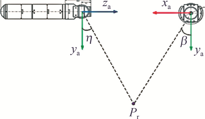
(4) 由载机坐标系投影至视轴坐标系下的双轴指向角度。如图 3所示,靶标指向范围为靶机机身后部2π立体空间,因此其轴线与载机轴线平行且方向相反,靶标双轴指向角度[10]计算过程如下式所示:
\left\{\begin{array}{l} \eta=\arctan \left(-\frac{x_{\mathrm{a}}}{y_{\mathrm{a}}}\right) \times 180 / \pi \\ \beta=\arctan \left(z_{\mathrm{a}} / \sqrt{x_{\mathrm{a}}^2+y_{\mathrm{a}}^2}\right) \times 180 / \pi \end{array}\right. (7) ![图 3 靶标旋转机构方向角和俯仰角求解原理]() 图 3 靶标旋转机构方向角和俯仰角求解原理Figure 3. Principle of direction angle and pitch angle of the target rotation mechanism
图 3 靶标旋转机构方向角和俯仰角求解原理Figure 3. Principle of direction angle and pitch angle of the target rotation mechanism式中,方向角η的范围为±180°,俯仰角β的旋转角度范围为0°~90°,Pr为固定目标点。
2. 指向误差建模
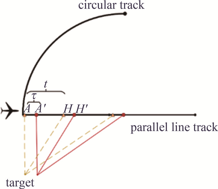
动态指向的简化过程如图 4所示。目标点静止,靶机携带靶标匀速飞行。在A处采集坐标及姿态角信息后经数据链下传,完成处理并产生驱动控制数据后通过数据链上传,经过时间t后,在H点进行下一次数据更新。在A′点完成指向动作,两点之间信息下传时间、上传时间、地面站处理时间及靶标指向动作响应时间[11-12]延时τ≈175 ms。
设靶机的飞行速率为v,其方位角为θ,则A′点在WGS-84坐标下位置可用下式表示:
\left\{\begin{aligned} L^{\prime}= & L_{\mathrm{f}}+\arctan \left[\frac{\sin \theta \times \sin (\tau v / a)}{\cos (\tau v / a)-\sin B_{\mathrm{f}} \sin B^{\prime}}\right] \\ B^{\prime}= & \arcsin \left[\sin B_{\mathrm{f}} \cos (\tau v / a)+\right. \\ & \left.\cos B_{\mathrm{f}} \sin (\tau v / a) \cos \theta\right] \end{aligned}\right. (8) 式中,(Bf,Lf,Hf)为目标在WGS-84坐标系下的纬度、经度及高度。
通过(7)式可知,靶标在A′点处水平和俯仰的实际指向角度及理论指向角度[13-14]分别可表示为(ηA′,βA′)及(ηA,βA),则在此处双轴的误差(Δη,Δβ)可表示为:
\left\{\begin{array}{l} \Delta \eta=\eta_{A^{\prime}}-\eta_A \\ \Delta \beta=\beta_{A^{\prime}}-\beta_A \end{array}\right. (9) 圆周飞行时的计算过程与之类似。
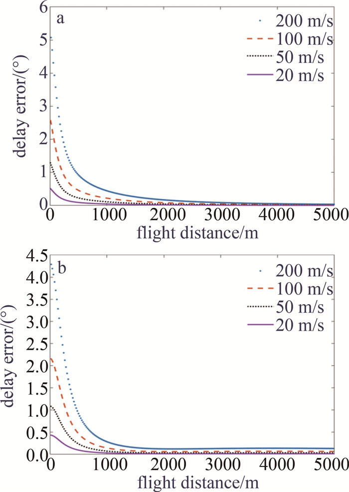
设目标点T的坐标为(东经116.00°,北纬40.00°,高度50 m),A点坐标为(东经116.00°,北纬40.01°,高度300 m),飞行方位角为45°,数据传输频率为10 Hz,测试航线长度为5000 m。分别按照速率为200 m/s、100 m/s、50 m/s、20 m/s的条件下飞行,直线飞行过程中指向角度误差如图 5a所示;从A点开始以半径r=3183.0988 m的圆形轨迹飞行时指向误差如图 5b所示。
![图 5 不同飞行轨迹下指向角度误差]() 图 5 不同飞行轨迹下指向角度误差a—直飞轨迹两轴合成指向角度误差 b—圆飞轨迹两轴合成指向角度误差Figure 5. Angle error in pointing under different flight trajectoriesa—two-axis synthetic pointing angle error of the direct trajectory b—two-axis synthetic pointing angle error of the circular trajectory
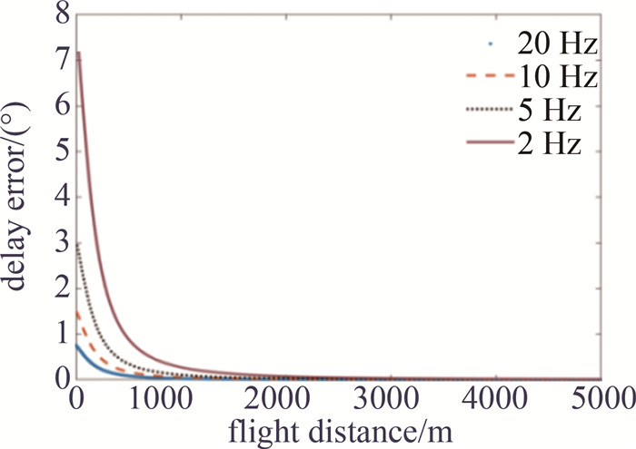
图 5 不同飞行轨迹下指向角度误差a—直飞轨迹两轴合成指向角度误差 b—圆飞轨迹两轴合成指向角度误差Figure 5. Angle error in pointing under different flight trajectoriesa—two-axis synthetic pointing angle error of the direct trajectory b—two-axis synthetic pointing angle error of the circular trajectory接下来以50 m/s速率匀速直飞状态下,改变靶标系统信息采样速率以分析数据采样频率对指向角度误差的影响。图 6表示采样频率分别以2 Hz、5 Hz、10 Hz和20 Hz与指向角度误差关系。
根据图 5和图 6可知,在其它条件相同的前提下,指向误差主要是由于从靶标位置采样时刻到指向动作执行完毕时刻内的系统位移导致的,该位移由飞行速度与位置信息采样时间间隔的乘积相关;因此提升位置信息采样频率均可有效减小靶标系统在各速度条件下指向误差。
靶标位置数据由载机机载GPS/INS系统测量,其采样速率通常较低(5 Hz),因此从硬件层面提升采样率工程可行性较低,为此本文作者提出通过卡尔曼滤波预测的方式,通过数据内插方式提升信息采样率,从而有效改善指向精度。
3. 基于卡尔曼滤波器的位置信息预测
基于第2节中的分析结论,拟通过卡尔曼滤波算法[15]在目标三轴姿态角及三轴加速度信息的基础上,对靶标的运动轨迹进行预测,从而达到提升位置信息采样率以减小指向误差的目的。
通过GPS/INS数据可得到当前靶标所在位置、速度和三轴姿态变化,在等高匀速飞行条件下不考虑高度对指向误差的影响,建立系统状态方程如下式所示:
\left\{\begin{array}{l} \boldsymbol{X}_k=\boldsymbol{A}_k \boldsymbol{X}_{k-1}{ }^{\prime}+\boldsymbol{G}_k \boldsymbol{w}_k \\ \boldsymbol{P}_k{ }^{\prime}=\boldsymbol{A}_k \boldsymbol{P}_{k-1} \boldsymbol{A}_k{ }^{\mathrm{T}}+\boldsymbol{G}_k \boldsymbol{Q}_k \boldsymbol{G}_k^{\mathrm{T}} \end{array}\right. (10) 由k-1时刻的最优状态Xk-1′估计k时刻的系统状态向量Xk=(xn,vn,xu,vu)T;(xn,xu)为垂直和水平方向每次更新的位置数据,(vn,vu)为垂直和水平方向每次更新的速度数据;同理,由上一次后验估计协方差Pk-1预测得到先验估计协方差为Pk′;wk为过程噪声矩阵,Qk为方差;Ak为k-1向k时刻的状态转移矩阵[16-18]:
\boldsymbol{A}_k=\left[\begin{array}{cccc} 1 & 1 & 0 & 0 \\ 0 & 1 & 0 & 0 \\ 0 & 0 & 1 & 1 \\ 0 & 0 & 0 & 1 \end{array}\right] (11) \boldsymbol{G}_k=\left[\begin{array}{cc} 0.5 \alpha_y & 0 \\ \alpha_y & 0 \\ 0 & 0.5 \alpha_z \\ 0 & \alpha_z \end{array}\right] (12) 式中,αy与αz分别表示横滚角和航向角的过程加速度,当惯导数据更新时,由飞行器飞行加速度和陀螺仪角速度信息得到预测解[19]。
系统观测方程Zk表示为:
\boldsymbol{Z}_k=\boldsymbol{H}_k \boldsymbol{X}_k+\boldsymbol{v}_k (13) 式中,Hk为测量矩阵;vk表示测量噪声矩阵,其方差为Rk,则滤波增益K可表示为[20]:
\boldsymbol{K}=\boldsymbol{H}_k P_k{ }^{\prime} \boldsymbol{H}_k^{\mathrm{T}}\left(\boldsymbol{H}_k \boldsymbol{P}_k \boldsymbol{H}_k^{\mathrm{T}}+\boldsymbol{R}_k\right)^{-1} (14) 根据系统状态Xk和滤波增益K得到k时刻最优解Xk′,并由下式更新后验估计协方差Pk[21],为下一步k+1时刻的最优指向角度进行迭代更新。
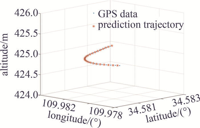
\left\{\begin{array}{l} \boldsymbol{X}_k^{\prime}=\boldsymbol{X}_k+\boldsymbol{K}\left(\boldsymbol{Z}_k-\boldsymbol{H}_k \boldsymbol{X}_k\right) \\ \boldsymbol{P}_k=\boldsymbol{P}_k^{\prime}-\boldsymbol{K} \boldsymbol{H}_k \boldsymbol{P}_k^{\prime} \end{array}\right. (15) 根据上述滤波公式,针对真实飞行数据轨迹进行插值,取1/10的GPS数据和预测数据效果,如图 7所示。可见通过此种方式预测的目标运动轨迹基本与实际趋于一致,靶标位置信息更新速率提升至原始数据的1倍。
4. 实际飞行试验
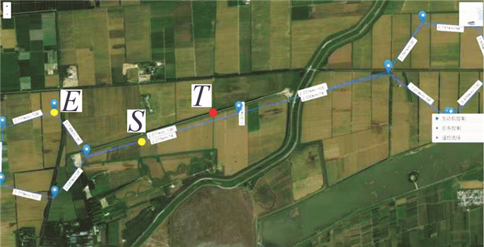
靶标系统实际挂载结构如图 8所示,其飞行轨迹如图 9所示。测试端从S点下发数据到E点停止,目标点位置为T,将飞行过程中记录的GPS/INS数据采用第3节中方法进行处理,获得两轴指向角在进行卡尔曼滤波算法插值方式提升采样率前后的指向误差。
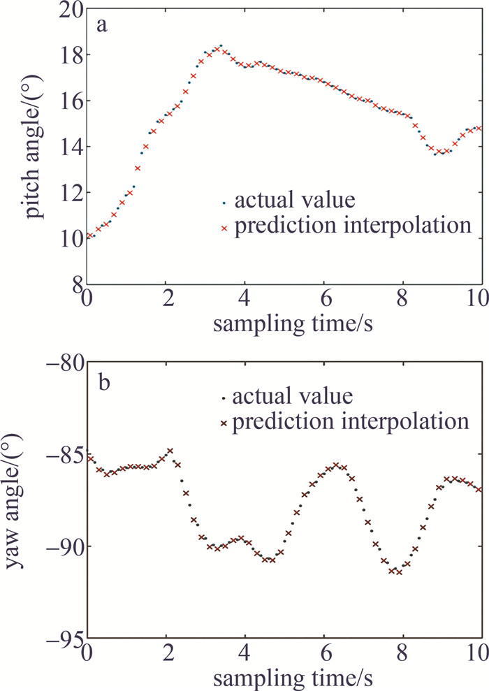
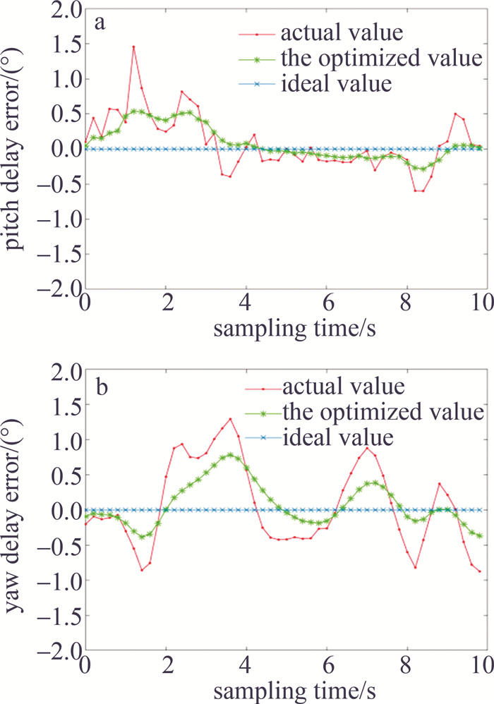
实际挂载飞行过程中俯仰和水平轴指向数据如图 10所示。靶标位置更新频率变快后可以使指向角度更新频率变快,并通过卡尔曼滤波算法优化位置信息后,指向精度有明显提高,图 11为优化后角度误差效果。
![图 10 双轴指向角度插值效果]() 图 10 双轴指向角度插值效果a—俯仰指向角度变化图 b—水平指向角度变化图Figure 10. Dual-axis pointing angle interpolation effecta—pitch angle points to the angle change graph b—yaw angle points to the angle change graph
图 10 双轴指向角度插值效果a—俯仰指向角度变化图 b—水平指向角度变化图Figure 10. Dual-axis pointing angle interpolation effecta—pitch angle points to the angle change graph b—yaw angle points to the angle change graph![图 11 双轴指向角度优化]() 图 11 双轴指向角度优化a—俯仰指向角度优化 b—水平指向角度优化Figure 11. Dual-axis pointing angle optimizationa—pitch angle points to the angle optimization plot b—yaw angle points to the angle optimization plot
图 11 双轴指向角度优化a—俯仰指向角度优化 b—水平指向角度优化Figure 11. Dual-axis pointing angle optimizationa—pitch angle points to the angle optimization plot b—yaw angle points to the angle optimization plot双轴在极坐标下指向角度平均误差数据结果见表 1。
表 1 双轴合成指向角度平均误差值Table 1. Average error value of the biaxial composite pointing anglesampling frequency/Hz average error of the pointing angle/(°) 5 0.397 10 0.180 通过本文中方法,将靶标位置信息更新速率由5 Hz提升至10 Hz时,双轴指向角度更新速度提升,在飞行试验范围内的最大指向角合成误差由0.397°下降至0.180°,将最大指向误差减小了54.66%。
5. 结论
针对一种新型靶标在空中挂载过程中的指向延时问题进行了理论分析和实验验证。分析了在不同的飞行态势和惯导数据更新频率对指向误差大小的影响,仿真结果表明,红外靶标在低速飞行时,位置及姿态信息的采样频率是指向误差的主要影响因素。为突破现有硬件系统对GPS数据更新速率的限制,提出了基于卡尔曼滤波算法的靶标位置信息进行预测的解决方法。挂载实验表明,该方法有效地减小了指向角误差,为实现减小红外辐射靶标的空中指向误差问题提供了一个有效的解决方案。
-
![]()
图 2 靶标指向坐标系变换示意图
Figure 2. Schematic of a target pointing to a coordinate system transformation
![]()
图 3 靶标旋转机构方向角和俯仰角求解原理
Figure 3. Principle of direction angle and pitch angle of the target rotation mechanism
![]()
图 5 不同飞行轨迹下指向角度误差
a—直飞轨迹两轴合成指向角度误差 b—圆飞轨迹两轴合成指向角度误差
Figure 5. Angle error in pointing under different flight trajectories
a—two-axis synthetic pointing angle error of the direct trajectory b—two-axis synthetic pointing angle error of the circular trajectory
![]()
图 10 双轴指向角度插值效果
a—俯仰指向角度变化图 b—水平指向角度变化图
Figure 10. Dual-axis pointing angle interpolation effect
a—pitch angle points to the angle change graph b—yaw angle points to the angle change graph
![]()
图 11 双轴指向角度优化
a—俯仰指向角度优化 b—水平指向角度优化
Figure 11. Dual-axis pointing angle optimization
a—pitch angle points to the angle optimization plot b—yaw angle points to the angle optimization plot
表 1 双轴合成指向角度平均误差值
Table 1 Average error value of the biaxial composite pointing angle
sampling frequency/Hz average error of the pointing angle/(°) 5 0.397 10 0.180  下载: 导出CSV
-
[1] 李博, 王伟娜, 唐杰. 新型光学动态靶标模拟空间目标研究[J]. 工程设计学报, 2008, 15(3): 201-205. DOI: 10.3785/j.issn.1006-754X.2008.03.010 LI B, WANG W N, TANG J. Study on simulation space aim of novel optical dynamic target[J]. Chinese Journal of Engineering Design, 2008, 15(3): 201-205(in Chinese). DOI: 10.3785/j.issn.1006-754X.2008.03.010
[2] 杨翔云, 吕勇, 刘洋, 等. 靶标系统中的目标红外特性建模技术研究[J]. 激光与红外, 2021, 51(10): 1336-1341. https://www.cnki.com.cn/Article/CJFDTOTAL-JGHW202110013.htm YANG X Y, LV Y, LIU Y, et al. Research on target infrared characteristic modeling technology in target system[J]. Laser & Infrared, 2021, 51(10): 1336-1341(in Chinese). https://www.cnki.com.cn/Article/CJFDTOTAL-JGHW202110013.htm
[3] 于晓杰, 郑永超, 郭崇岭, 等. 不同背景下高超声速飞行器红外可探测性分析[J]. 激光技术, 2018, 42(5): 627-632. DOI: 10.7510/jgjs.issn.1001-3806.2018.05.009 YU X J, ZHENG Y Ch, GUO Ch L, et al. Analysis of infrared detectability hypersonic vehicles under different background[J]. Laser Technology, 2018, 42(5): 627-632(in Chinese). DOI: 10.7510/jgjs.issn.1001-3806.2018.05.009
[4] 陈刚, 周超, 刘红光. 时间延迟对姿态角匹配传递对准的影响[J]. 中国惯性技术学报, 2014, 22(2): 172-176. https://www.cnki.com.cn/Article/CJFDTOTAL-ZGXJ201402006.htm CHEN G, ZHOU Ch, LIU H G. Influence of time delay for attitude angle matching transfer alignment[J]. Journal of Chinese Inertial Technology, 2014, 22(2): 172-176(in Chinese). https://www.cnki.com.cn/Article/CJFDTOTAL-ZGXJ201402006.htm
[5] 叶德茂, 谢利民, 陈晶. 跟踪误差补偿下星地光通信地面模拟实验分析[J]. 激光技术, 2012, 36 (3): 346-348. http://www.jgjs.net.cn/article/id/9501 YE D M, XIE L M, CHEN J. Ground simulation analysis of satellite-ground optical communication based on tracking error compensation[J]. Laser Technology, 2012, 36 (3): 346-348(in Chinese) http://www.jgjs.net.cn/article/id/9501
[6] 谢木军, 马佳光, 傅承毓, 等. 空间光通信中的精密跟踪瞄准技术[J]. 光电工程, 2000, 27(1): 13-16. https://www.cnki.com.cn/Article/CJFDTOTAL-GDGC200001002.htm XIE M J, MA J G, FU Ch Y, et al. Precision tracking and pointing technologies in space optical communication[J]. Opto-Electronic Engineering, 2000, 27(1): 13-16(in Chinese). https://www.cnki.com.cn/Article/CJFDTOTAL-GDGC200001002.htm
[7] 吴若溪. 空间光通信系统视轴指向技术研究[D]. 长春: 长春理工大学, 2020: 1-64. WU R X. Research on line-of-sight pointing technology of spatial optical communication system[D]. Changchun: Changchun University of Science and Technology, 2020: 1-64(in Chinese).
[8] 赵馨, 刘云清, 佟首峰. 动态空间激光通信系统视轴初始指向建模及验证[J]. 中国激光, 2014, 41(5): 0505009. https://www.cnki.com.cn/Article/CJFDTOTAL-JJZZ201405028.htm ZHAO X, LIU Y Q, DONG Sh F. Line-of-sight initial alignment model and test in dynamic space laser communication[J]. Chinese Journal of Lasers, 2014, 41(5): 0505009(in Chinese). https://www.cnki.com.cn/Article/CJFDTOTAL-JJZZ201405028.htm
[9] 张玉碟, 柳万胜, 罗一涵, 等. 一种三轴光电跟踪系统指向误差修正的方法[J]. 光电工程, 2014, 41(6): 51-55. https://www.cnki.com.cn/Article/CJFDTOTAL-GDGC201406010.htm ZHANG Y D, LIU W Sh, LUO Y H, et al. Pointing error modification method for three-axis optoelectronic tracking system[J]. Opto-Electronic Engineering, 2014, 41(6): 51-55(in Chinese). https://www.cnki.com.cn/Article/CJFDTOTAL-GDGC201406010.htm
[10] 丁继成, 李冠男, 班镜超. 基于双轴位置转台的捷联惯导系统级标定技术[J]. 舰船科学技术, 2015, 37(4): 76-78. DING J Ch, LI G N, BAN J Ch. Research on SINS systematic calibration technique based on dual-axis turntable[J]. Ship Science and Technology, 2015, 37(4): 76-78(in Chinese).
[11] 吴训涛, 高青伟. 传递对准中时间延迟误差补偿与滤波模型[J]. 四川兵工学报, 2012, 33(5): 14-17. https://www.cnki.com.cn/Article/CJFDTOTAL-CUXI201205005.htm WU X T, GAO Q W. Time delay error compensation and filtering model in pass alignment[J]. Journal of Ordnance Equipment Engineering, 2012, 33(5): 14-17(in Chinese). https://www.cnki.com.cn/Article/CJFDTOTAL-CUXI201205005.htm
[12] 陈雨, 赵剡, 李群生, 等. 快速传递对准中主惯导信息滞后补偿方法[J]. 中国惯性技术学报, 2013, 21(5): 576-580. https://www.cnki.com.cn/Article/CJFDTOTAL-ZGXJ201305004.htm CHEN Y, ZHAO Y, LI Q Sh, et al. Compensation method for master inertial navigation system information delay in rapid transfer alignment[J]. Journal of Chinese Inertial Technology, 2013, 21(5): 576-580(in Chinese). https://www.cnki.com.cn/Article/CJFDTOTAL-ZGXJ201305004.htm
[13] 韩成, 佟首峰, 陈展东, 等. GPS/INS系统误差对空间激光通信对准算法的影响分析[J]. 红外与激光工程, 2009, 38(4): 650-654. https://www.cnki.com.cn/Article/CJFDTOTAL-HWYJ200904019.htm HAN Ch, TONG Sh F, CHEN Zh D, et al. Analysis of influence of GPS/INS system errors on pointing algorithm in space optical communication[J]. Infrared and Laser Engineering, 2009, 38(4): 650-654(in Chinese) https://www.cnki.com.cn/Article/CJFDTOTAL-HWYJ200904019.htm
[14] 彭丁聪. 卡尔曼滤波的基本原理及应用[J]. 软件导刊, 2009, 8(11): 32-34. https://www.cnki.com.cn/Article/CJFDTOTAL-RJDK200911011.htm PENG D C. Basic principles and applications of Kalman filtering[J]. Software Guide, 2009, 8(11): 32-34(in Chinese). https://www.cnki.com.cn/Article/CJFDTOTAL-RJDK200911011.htm
[15] 聂琦. 非线性滤波及其在导航系统中的应用[D]. 哈尔滨: 哈尔滨工程大学, 2008: 63-92. NIE Q. Nonlinear filtering and its application in navigation system[D]. Harbin: Harbin Engineering University, 2008: 63-92(in Ch-inese).
[16] 蒋晓东, 于纪言, 朱立坤. 基于位置敏感探测器的组合导航技术研究[J]. 激光技术, 2019, 43(3): 335-340. DOI: 10.7510/jgjs.issn.1001-3806.2019.03.009 JANG X D, YU J Y, ZHU L K. Research of combined navigation technology based on position sensitive detectors[J]. Laser Technology, 2019, 43(3): 335-340(in Chinese). DOI: 10.7510/jgjs.issn.1001-3806.2019.03.009
[17] 吴若溪, 董岩, 田成军, 等. 基于卡尔曼滤波的激光通信视轴指向技术[J]. 光通信技术, 2018, 42(9): 30-32. https://www.cnki.com.cn/Article/CJFDTOTAL-GTXS201809009.htm WU R X, DONG Y, TIAN Ch J, et al. Line-of-sight pointing technology of laser communication system based on Kalman filter[J]. Optical Communication Technology, 2018, 42(9): 30-32(in Ch-inese). https://www.cnki.com.cn/Article/CJFDTOTAL-GTXS201809009.htm
[18] 于周吉, 傅军, 韩洪祥. MEMS陀螺随机误差建模及补偿应用研究[J]. 舰船电子工程, 2019, 39(8): 76-78. https://www.cnki.com.cn/Article/CJFDTOTAL-JCGC201908019.htm YU Zh J, FU J, HAN H X. Research on modeling and compensation application of MEMS gyro stochastic error[J]. Ship Electronic Engineering, 2019, 39(8): 76-78(in Chinese). https://www.cnki.com.cn/Article/CJFDTOTAL-JCGC201908019.htm
[19] 王新龙, 陈涛, 杜宇. 基于ARMA模型的光纤陀螺漂移数据建模方法研究[J]. 弹箭与制导学报, 2006, 26(1): 5-7. https://www.cnki.com.cn/Article/CJFDTOTAL-DJZD200601001.htm WANG X L, CHEN T, DU Y. The drift method of fiber optic gyros based on the ARMA model[J]. Journal of Projectiles, Rockets, Missiles and Guidance, 2006, 26(1): 5-7(in Chinese). https://www.cnki.com.cn/Article/CJFDTOTAL-DJZD200601001.htm
[20] 韩明, 唐心亮, 孟军英, 等. 改进的卡尔曼滤波与均值漂移目标跟踪算法[J]. 战术导弹技术, 2019(1): 115-123. https://www.cnki.com.cn/Article/CJFDTOTAL-ZSDD201901018.htm HAN M, TANG X L, MENG J Y, et al. Target tracking algorithm based on improved Kalman filter and mean-shift[J]. Tactical Missile Technology, 2019(1): 115-123(in Chinese). https://www.cnki.com.cn/Article/CJFDTOTAL-ZSDD201901018.htm
[21] 林旭, 刘俊钊. 有色噪声下的目标跟踪卡尔曼滤波新算法[J]. 中国惯性技术学报, 2018, 26(6): 830-834. https://www.cnki.com.cn/Article/CJFDTOTAL-ZGXJ201806021.htm LIN X, LIU J Zh. New Kalman filtering algorithm for target tracking with colored noise[J]. Journal of Chinese Inertial Technology, 2018, 26(6): 830-834(in Chinese). https://www.cnki.com.cn/Article/CJFDTOTAL-ZGXJ201806021.htm

计量
- 文章访问数: 3
- HTML全文浏览量: 6
- PDF下载量: 7