Optical design of external drum thermal CTP equipment
-
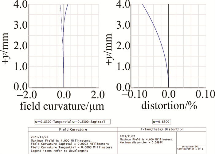
摘要: 为了解决外鼓式热敏计算机直接制版(CTP)设备的制版镜头因畸变、场曲过大而导致制版质量不良问题, 采用ZEMAX光学仿真软件, 设计了一款低畸变、低场曲的制版镜头光学系统, 并对其进行了公差分析和实验验证。结果表明, 该光学系统由6片透镜组成, 工作波长为830 nm, 场曲小于1 μm, 畸变小于0.1%, 调制传递函数在全视场200 lp/mm处大于0.7, 并且镜片都采用标准球面设计, 制版效果良好。该系统能够满足实际制版生产需求, 具有一定的市场前景。Abstract: In order to solve the problem of poor plate-making quality caused by distortion and field curvature of the plate-making lens of the external drum thermal computer to plate (CTP)equipment, a low-distortion and low-field-curvature plate-making lens optical system was designed using ZEMAX software. Tolerance analysis and experimental verification have been carried out. The results show that the optical system is consisted of six lenses, the working wavelength is 830 nm, the field curvature is less than 1 μm, the distortion is less than 0.1%, and the modulation transfer function is greater than 0.7 at the full field of view of 200 lp/mm. All the lenses in this system are designed with a standard spherical surface, and the plate-making effect is good, which can meet the actual plate-making production needs, and has a certain market prospect.
-
Keywords:
- optical design /
- computer to plate /
- ZEMAX software /
- error analysis
-
引言
激光熔覆技术是一种兼顾精确成形和高性能成形一体化需求的先进制造技术, 也是中国制造2025年重点发展的先进制造技术[1-2]。激光熔覆技术的基本原理是在基体表面上熔凝金属、陶瓷粉末使之与基体形成稀释度极低且与基体成冶金结合的熔覆层, 可以作为易磨损零件的修复方法, 有效改善基体表面的耐磨、耐腐蚀、抗氧化等性能, 激光熔覆技术的这些特点使其在基体修复和表面改性领域具有广阔的发展前景[3-5]。激光熔覆技术对金属表面进行熔覆涂层以达到基材表面改性的技术, 在机械用钢的回收和修复中具有广阔的发展空间[16-19], 并可极大扩展钢材的应用空间, 降低产品制造成本。由于激光熔覆是一个金属快速熔凝的过程, 就使得表面熔覆层质量不易控制, 在熔覆层中易产生裂纹和气孔等缺陷, 影响熔覆层的整体性能, 这使解决熔覆层中的裂纹和气孔成为激光熔覆技术中的关键问题。
熔覆层中的裂纹主要是由于金属凝固时熔池内部温度和基材温度梯度大、熔池内部的残余应力导致的, 也跟熔覆材料与基体材料的热膨胀系数差异也有关。由于这些因素对熔覆层质量的影响, 使得激光熔覆技术是一项复杂技术。激光熔覆中的功率、光斑大小、扫描速率、离焦量等主要参量对熔覆层的质量有着决定性作用[6-13], 参量之间的相互匹配和优化对熔覆层的质量有重要影响。
激光熔覆热源是由光纤激光发生器产生的强激光束。熔池中的热源能量密度Es可表示为:Es=P/(Dv), 其中, P为激光功率, v为激光扫描速率, D为激光束光斑直径。大量研究表明[14-15], 激光熔覆层易产生裂纹, 与熔池在遇冷凝固的过程中熔池内部的残余应力有关, 而残余应力的大小和激光能量密度Es紧密相关。当激光能量密度Es在一定范围增大时, 熔覆层的开裂倾向会减少。但激光功率过大会使得基材吸收的热量过高, 导致基体变形严重。适当地降低扫描速率可以增大激光能量密度Es, 这是由于随着扫描速率降低, 扫描时间变长, 熔池吸收热量增加, 熔池深度也相应地增加, 使得材料温度梯度减小, 熔池冷却速率减缓, 减小由温度梯度引起的热应力, 从而减小了开裂倾向。这种改变激光扫描速率来控制熔池温度的方法比控制激光功率对基材的影响较小。
45#钢在极端条件下易发生腐蚀、疲劳、破损等失效形式, 可以在45#钢的表面采用激光熔覆技术熔覆合金涂层提高综合性能。本文中主要分析多道搭接熔覆实验中, 激光扫描速率对45#钢基材上熔覆镍基合金粉末的熔覆层性能和熔覆层裂纹的影响。
1. 实验材料及方法
1.1 试验材料
试验前材料处理:为了防止基材表面杂质对激光能量的吸收从而影响实验结果, 试验前对45#钢进行表面精磨, 使基体表面平整, 使用无水乙醇清洗去除表面油污和氧化膜, 使基体表面无明显缺陷。为了防止镍基熔覆粉末受潮造成结块对实验结果产生影响, 在实验开始前对镍基熔覆粉末真空烘干除潮, 避免因熔覆粉末受潮。熔覆过程中施加氮气保护, 可以保护熔覆层成型过程中不受氧化等外界干扰得到均匀且性能稳定的激光熔覆涂层。45#钢基材的化学成分如表 1所示。
Table 1. Chemical composition (mass fraction) of 45# steel matrixC Si Mn Cr Ni Cu P, Fe 0.005 <0.002 <0.001 ≤ 0.001 <0.001 ≤ 0.001 balance 选取Ni60自熔合金粉末为熔覆材料, Ni60的化学成分如表 2所示。
Table 2. Chemical composition (mass fraction) of Ni60 alloy powderSi C Fe B Cr Ni 0.008 0.001 0.003 0.031 0.003 balance 1.2 试验设备与方法
试验设备包括:(1)IPG光纤激光器, 型号为YLS-2000, 最大输出功率P=2000W;(2)HV-1000型数字显微硬度计; (3)JSM-6700F场发射扫描电镜(scanning electron microscope, SEM)。
表 3为在45#钢基材上优化后的激光熔覆工艺参量。
Table 3. Process parameters of laser claddinglaser
power/
kWspot
diameter/
mmpulverized
speed/
(g·s-1)scanning
speed/
(mm·s-1)lap
rate/
%defocus/
mm1.4 2 1.2 2, 3, 4 50 16 对熔覆后的试样用线切割设备沿成形截面切开, 制作成8mm×8mm×8mm大小的试块, 用砂纸进行打磨获得显微硬度测试件, 显微硬度测量采用HV-1000型数字显微硬度计。对获得8mm×8mm×8mm的试块进行打磨、抛光, 用丙酮溶液清洗试样, 并用王水腐蚀, 制成电镜扫描试块, 采用JSM-6700F场发射扫描电镜对试块进行显微形貌和断面结构分析。
2. 实验结果及分析
2.1 单道宏观形貌图
图 1是激光扫描速率为2mm/s, 4mm/s, 6mm/s时45#钢表面熔覆单道Ni60涂层的宏观形貌。
在单道激光熔覆涂层的对比中, 激光扫描速率为2mm/s时, 基材表面氧化严重, 基材和粉末吸收的热量高使得粉末得以充分熔化, 获得的熔池深度较大, 但是基材吸收热量高, 基材背面存在热影响区, 熔覆高度相比较激光扫描速率为4mm/s和6mm/s时有明显提高。激光扫描速率为2mm/s时, 熔覆层表面最光滑, 扫描速率为4mm/s时, 相较于6mm/s时熔覆层宽度和厚度都有增加。
2.2 多道宏观形貌图
图 2是2mm/s, 4mm/s, 6mm/s 3种激光扫描速率搭接率为50%时的多道搭接熔覆层的宏观形貌图。
在3种激光扫描速率下粉末均能与基材形成冶金结合, 当激光扫描速率为2mm/s时, 基材氧化严重, 熔覆层表面呈波浪状、表面平整度差, 基材形变量大, 这是由于激光扫描速率过慢、基材吸收的热量过多引起的, 熔覆层的厚度也由于速率低使得镍基粉末熔覆层高于激光熔覆扫描速率为4mm/s和6mm/s时, 3种激光熔覆扫描速率下熔覆层表面均无明显的气孔和裂纹。
2.3 不同扫描速率下涂层硬度
图 3为3种不同激光扫描速率熔覆层表面到基体的显微硬度变化趋势。采用数字显微硬度计分别对激光扫描速率为2mm/s, 4mm/s, 6mm/s的试样进行显微硬度测量。为了减小测量误差, 每个试样的横向水平测量层分别测量3个点, 每个测量点之间相隔2mm, 然后再取平均值。不同激光扫描速率熔覆层的显微硬度从熔覆层顶部开始测量, 每隔1.8mm为一个测量点。
由图 3可知, 激光熔覆层的显微硬度随着离基体的距离减小而减小, 熔覆涂层的厚度在一定范围内影响整体显微硬度。熔覆层顶部受环境中氧气影响, 会形成复杂氧化物的表面氧化膜, 显微硬度波动较大。激光熔覆层中部熔池受到外部环境影响较小, 使得熔覆层中部的熔池能够凝固成晶粒细小的组织, 使得显微硬度高于底部。由于激光热辐射对基材表面进行了表面改性, 熔化了的基材通过熔池中的对流传质作用, 扩散到熔覆层中, 造成基材稀释度的增大, 从而熔覆层成分有较大改变, 使熔覆层中各组成相的形态和大小均发生了相应的变化, 结合区的显微硬度高于基体的显微硬度, 起到连接熔覆层和基体的过渡作用。测量结果表明, 熔覆层的显微硬度平均值比基体的显微硬度值提高了500HV左右, 实现了对45#钢表面强化的目的。
2.4 熔覆层微观组织
图 4是激光扫描速率为2mm/s, 4mm/s, 6mm/s时熔覆后试样的扫描电镜形貌。
由图 4可以看出, 3种激光扫描速率形成的晶粒致密, 无明显的裂纹和气孔产生, 但晶粒的大小随着激光扫描速率的增加先减小后增大, 这是由于熔覆层晶粒的细密程度与生长温度有关, 在一定范围内激光熔覆扫描速率越低, 获得的金属熔池温度越高, 晶粒的成长也就越细密。图 4中深色晶粒为硼化物, 扫描速率在一定范围内的的增加使得硼化物晶粒细小。扫描速率为2mm/s时, 熔池温度过高硼化物晶粒散乱, 熔覆层质量不均匀。扫描速率为4mm/s时, 硼化物晶粒细小且排布相对整齐, 熔覆层性能相较于扫描速率为2mm/s和6mm/s时波动较小, 具体表现为图 3中扫描速率为4mm/s时熔覆层显微硬度波动较小。
3. 结论
(1) 激光熔覆的扫描速率对熔覆层表面粗糙度、表面平整度和基材热影响区有重要影响, 随着扫描速率的提高, 表面粗糙度升高, 熔覆层厚度降低, 基材熔化深度减小。
(2) 在45#钢上熔覆镍基(Ni60)合金粉末的熔覆层比基材的显微硬度高出约500HV。熔覆层晶粒的细密程度与扫描速率有关, 扫描速率过高或过低都会使得熔覆层晶粒减小、显微硬度降低。
(3) 3种激光熔覆扫描速率形成的熔覆层, 都未产生明显的裂纹和气孔等缺陷, 在激光扫描速率为4mm/s时, 形成的熔覆层表面平整, 微观组织无裂纹产生, 硼化物晶粒致密, 显微硬度波动较小。
-
表 1 外鼓式热敏CTP镜头主要设计指标
Table 1 Main specifications of external drum thermal CTP lens
specification parameter wavelength 830 nm reduce magnification 3.83 numerical aperture 0.1~0.12 conjugate distance 180 mm~220 mm curvature of field <1 μm distortion <0.1% relative illumination >0.95 表 2 公差要求
Table 2 Tolerance requirements
the tolerance category value radius 2N thickness 0.02 mm decenter 0.01 mm tilt 0.013° spherical and astigmatism irregularity 0.2 abbe 0.5% index 0.0005 表 3 蒙特卡洛公差分析结果
Table 3 Result of Monte Carlo tolerance analysis
benign rate value >90% 0.53350854 >80% 0.57671560 >50% 0.63829413 >20% 0.68124155 >10% 0.69663692 表 4 制版及印刷主要条件与参数
Table 4 Main conditions and parameters of plate making and printing
type value working temperature 25 ℃ relative humidity 60% resolution 2400 DPI laser energy 130 mJ/cm2 the rotational speed of the photosensitive drum 900 r/min photographic developer Hua Guang TPD-85 thermal CTP plate Hua Guang TP-ⅡⅩ thermal CTP plate -
[1] 季永芹. CTP及其系统的应用研究[D]. 武汉: 武汉大学, 2005: 19-30. JI Y Q. Applied research on the CTP and the system[D]. Wuhan: Wuhan University, 2005: 19-30(in Chinese).
[2] 李嘉明. 计算机直接制版(CTP)机的现状及发展[J]. 影像技术, 2010, 22(1): 14-28. https://www.cnki.com.cn/Article/CJFDTOTAL-YIXI201001006.htm LI J M. Status quo and development of CTP setters[J]. Image Technology, 2010, 22(1): 14-28(in Chinese). https://www.cnki.com.cn/Article/CJFDTOTAL-YIXI201001006.htm
[3] 何丽莉, 韩伟. 热敏CTP技术特点及应用发展[J]. 机械管理开发, 2012(5): 105-106. https://www.cnki.com.cn/Article/CJFDTOTAL-JSGL201205057.htm HE l l, HAN W. Technical features and application development of therma CTP[J]. Mechanical Management and Development, 2012(5): 105-106(in Chinese). https://www.cnki.com.cn/Article/CJFDTOTAL-JSGL201205057.htm
[4] 张黎烁. 热敏型激光计算机的直接制版板材研成[J]. 激光杂志, 2015, 36(7): 128-130. https://www.cnki.com.cn/Article/CJFDTOTAL-JGZZ201507035.htm ZHANG L Sh. The direct plate making plate of thermal sensitive laser computer[J]. Laser Journal, 2015, 36(7): 128-130(in Chinese). https://www.cnki.com.cn/Article/CJFDTOTAL-JGZZ201507035.htm
[5] 丁宏波. CTP版基的应用及生产技术[J]. 有色金属加工, 2012, 41(4): 19-21. DOI: 10.3969/j.issn.1671-6795.2012.04.008 DING H B. Application and productive technology of CTP forme base[J]. Nonferrous Metals Processing, 2012, 41(4): 19-21(in Chinese). DOI: 10.3969/j.issn.1671-6795.2012.04.008
[6] 卢华生. 免化学处理热敏CTP版材的开发[D]. 北京: 北京印刷学院, 2013: 42-53. LU H Sh. Development of chemical-free thermo-sensitive STP plate[D]. Beijing: Beijing Institute of Graphic Communication, 2013: 42-53(in Chinese).
[7] 范兆东, 孙中华. CTP激光光源及技术分析[J]. 影像技术, 2009, 21(3): 42-44. https://www.cnki.com.cn/Article/CJFDTOTAL-YIXI200903012.htm FAN Zh D, SUN Zh H. Laser light sources for CTP and their technologies analysis[J]. Image Technology, 2009, 21(3): 42-44(in Chinese). https://www.cnki.com.cn/Article/CJFDTOTAL-YIXI200903012.htm
[8] 李和伟, 王钦久. CTP制版机扫描光源类型及成像材料的感光特性[J]. 印刷世界, 2008(1): 31-34. https://www.cnki.com.cn/Article/CJFDTOTAL-YINS200801022.htm LI H W, WANG Q J. Type of scanning light source of CTP plate making machine and photosensitive characteristics of imaging material[J]. Print World, 2008(1): 31-34(in Chinese). https://www.cnki.com.cn/Article/CJFDTOTAL-YINS200801022.htm
[9] 谢峰, 宋勇亨. 热敏CTP版制版感度与制版质量[J]. 化工管理, 2015(23): 119. https://www.cnki.com.cn/Article/CJFDTOTAL-FGGL201523098.htm XIE F, SONG Y H. Thermal CTP plate-making sensitivity and plate-making quality[J]. Chemical Enterprise Management, 2015(23): 119(in Chinese). https://www.cnki.com.cn/Article/CJFDTOTAL-FGGL201523098.htm
[10] 吕明珠. 热敏CTP系统制版质量的控制方法[J]. 今日印刷, 2014(1): 57-60. https://www.cnki.com.cn/Article/CJFDTOTAL-JRYS201401025.htm LV M Zh. Control method of plate-making quality in thermal CTP system[J]. Print Today, 2014(1): 57-60(in Chinese). https://www.cnki.com.cn/Article/CJFDTOTAL-JRYS201401025.htm
[11] 曾琦. 热敏CTP在制版过程的质量控制与检测[D]. 济南: 齐鲁工业大学, 2012: 42-66. ZENG Q. Quality control and measuring of thermal CTP in plate-making process[D]. Ji'nan: Qilu University of Technology, 2012: 42-66(in Chinese).
[12] 蒋青言. CTP制版质量控制方法的研究[D]. 天津: 天津科技大学, 2012: 13-35. JIANG Q Y. Research on the quality control method of computer to plate[D]. Tianjin: Tianjin University of Science and Technology, 2012: 13-35(in Chinese).
[13] 冷彩凤, 赵骁, 王兴. CTP版网点复制的质量研究[J]. 陕西科技大学学报(自然科学版), 2014, 32(5): 32-35. https://www.cnki.com.cn/Article/CJFDTOTAL-XBQG201405007.htm LENG C F, ZHAO X, WANG X. A research of the quality of the dot copy in the CTP plate[J]. Journal of Shaanxi University of Science & Technology(Natural Science Edition), 2014, 32(5): 32-35(in Chin-ese). https://www.cnki.com.cn/Article/CJFDTOTAL-XBQG201405007.htm
[14] 郝清霞, 郑亮, 刘艳, 等. 数字印前技术[M]. 北京: 印刷工业出版社, 2007: 3. HAO Q X, ZHENG L, LIU Y, et al. Digital prepress technology[M]. Beijing: Beijing Printing Industry Press, 2007: 3(in Ch-inese).
[15] 方针, 赵军, 陈文友. 采用声光调制技术的激光照排系统[J]. 压电与声光, 1996(4): 235-239. https://www.cnki.com.cn/Article/CJFDTOTAL-YDSG604.004.htm FANG Zh, ZHAO J, CHEN W Y. A laser typesetting system using acoustooptic modulating technology[J]. Piezoelectrics & Acoustooptics, 1996, 18(4): 235-239(in Chinese). https://www.cnki.com.cn/Article/CJFDTOTAL-YDSG604.004.htm
[16] 邢洁芳, 范静, 张杰, 等. 热敏CTP激光光纤密排设计[J]. 包装工程, 2010, 31(23): 85-88. https://www.cnki.com.cn/Article/CJFDTOTAL-BZGC201023025.htm XING J F, FAN J, ZHANG J, et al. Design of laser dense fiber of heat-sensitive CTP[J]. Packaging Engineering, 2010, 31(23): 85-88(in Chinese). https://www.cnki.com.cn/Article/CJFDTOTAL-BZGC201023025.htm
[17] 邢洁芳, 刘真, 范静. 热敏CTP激光测控条及应用[J]. 包装工程, 2010, 31(1): 86-89. https://www.cnki.com.cn/Article/CJFDTOTAL-BZGC201001025.htm XING J F, LIU Zh, FAN J. Evaluations of laser imaging quality of thermal CTP[J]. Packaging Engineering, 2010, 31(1): 86-89(in Chinese). https://www.cnki.com.cn/Article/CJFDTOTAL-BZGC201001025.htm
[18] 王国联. 数字印版测控条在热敏CTP版材质量管控中的应用[J]. 网印工业, 2020(11): 28-29. https://www.cnki.com.cn/Article/CJFDTOTAL-WYGY202011010.htm WANG G L. The application of digital printing plate measurement and control strip in quality control of thermal CTP plate[J]. Screen Printing Industry, 2020(11): 28-29(in Chinese). https://www.cnki.com.cn/Article/CJFDTOTAL-WYGY202011010.htm
[19] 唐晖. 一种CTP焦距调整系统: 中国, CN203573084U[P]: 2014-04-30. TANG H. A CTP focal length adjustment system: China CN203573084U[P]. 2014-04-30(in Chinese).
[20] 李兴光, 梁汉斌. 一种光学成像位置检测方法及其装置: 中国CN103307972A[P]. 2013-09-18. LI X G, LIANG H B. Method and device for detecting optical imaging position: China CN103307972A[P]. 2013-09-18(in Chinese).


 下载:
下载:


