Study on the effect of laser cladding composite coating and its WC on crack formation mechanism
-
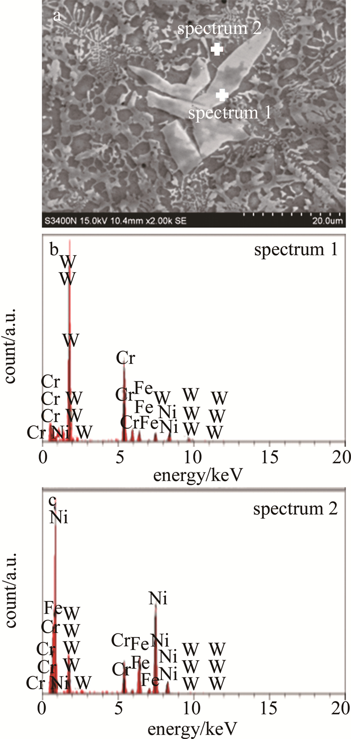
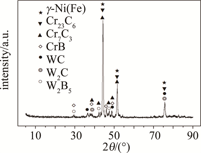
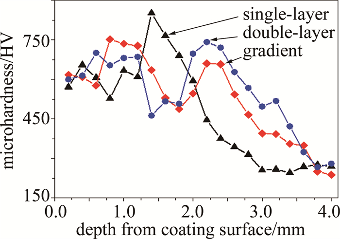
摘要: 为了研究复合涂层中碳化钨(WC)组织演变对裂纹产生的影响机理, 采用单层激光熔覆、过渡层梯度熔覆与双层熔覆制备3种Ni50A/WC复合涂层对比的方法, 分析涂层的形貌与组织、裂纹产生特点以及原因, 探究WC的组织演变对裂纹产生的影响。结果表明, 不同熔覆方法的WC组织演变对裂纹产生的影响主要由残余WC颗粒内部开裂形成裂纹源、硬质相元素引起成分偏析等作用组成; 双层熔覆、梯度熔覆涂层与单层熔覆涂层相比, 由于粉末吸收了更多的能量, 残余WC颗粒含量降低了32.7%与37.9%, 减少了涂层内部裂纹源; 共晶化合物的W元素质量分数也从单层熔覆涂层的0.534分别下降到双层熔覆涂层的0.417与梯度熔覆涂层的0.386, 降低了硬质相元素集中程度, 减少了涂层成分偏析, 降低了涂层开裂敏感性。该研究对改善激光熔覆复合涂层的开裂问题、提高复合涂层的成品率有一定的指导意义。Abstract: In order to study the influence mechanism of WC microstructure evolution on crack generation in composite coating, three Ni50A/WC composite coatings were prepared by single-layer laser cladding, transition layer gradient cladding and double-layer cladding. The morphology and structure of coating, crack generation characteristics, and the causes of crack were analyzed. The influence of WC microstructure evolution on crack generation was then explored. The results show that the influence of microstructure evolution of WC by different cladding methods on crack generation is mainly caused by internal cracking of residual WC particles. Compared with the monolayer cladding coating, the content of residual WC particles decreased by 32.7% and 37.9% due to the absorption of more energy by the powder of double-layer cladding and gradient cladding coating, and the source of cracks in the coating was reduced. In addition, the mass fraction of W element in eutectic compounds decrease from 0.534 of monolayer cladding coating to 0.417 of double cladding coating and 0.386 of gradient cladding coating, which reduced the concentration of hard phase elements, composition segregation and cracking sensitivity of coating. This research has certain guiding significance to improve the cracking of laser cladding composite coating and improve the yield of composite coating.
-
Keywords:
- laser technique /
- composite coating /
- microstructural evolution /
- crack /
- WC
-
引言
自20世纪90年代以来,啁啾脉冲放大技术的出现见证了激光技术的蓬勃发展。如今超短超强激光脉冲的闪亮时间早已达到飞秒[1-2]甚至阿秒[3-6]量级。超短超强激光脉冲的发展在X射线[7-9]、医疗行业[10]和天体物理[11]等研究领域也有着重要的贡献。
在非线性汤姆逊散射[12-14]中,入射激光脉冲的各种参数会影响电子的运动轨迹和辐射特性。例如WANG等人[15]研究了不同脉冲宽度下紧密聚焦圆偏振激光脉冲的非线性汤姆逊散射。LI[16]和WANG[17]等人研究了不同激光强度下圆极化聚焦照射电子的运动和空间辐射特性。YAN等人[18]研究了电子初始位置对高能电子辐射的影响。YU[19]和WU[20]等人研究了不同束腰半径的激光脉冲对电子的影响。而SHI等人[21]发现了在椭圆偏振激光脉冲中,随着脉冲宽度的增加,电子的空间辐射分布有更多的局部极大值集且每组有4个局部极大值。本文作者也是在椭圆偏振激光脉冲的基础上进行研究,但与SHI等人不同的是,本文中研究了超短超强椭圆激光脉冲的初始相位对高能电子运动轨迹和辐射功率空间分布的影响。
作者探讨了高能电子在激光场中的运动,应用Lorentz方程与电子能量方程建立强激光场与单个高能电子的对撞模型,对不同初始相位的椭圆偏振脉冲激光场对撞高能电子所产生的空间辐射功率图像进行模拟,详细讨论了椭圆偏振激光脉冲的初始相位对于高能电子产生辐射功率空间分布的影响,能够通过高能电子辐射功率的空间分布探测出超短超强椭圆偏振激光脉冲的初始相位。
1. 单电子对撞辐射模型
紧聚焦高斯脉冲激光电场的归一化矢势a(η)可以表示为:
\boldsymbol{a}(\eta)=a(\cos \varphi \cdot \boldsymbol{x}+\delta \sin \varphi \cdot \boldsymbol{y}) (1) a=\frac{b_0}{b} a_0 \exp \left(-\frac{\eta^2}{L^2}-\frac{\rho^2}{b^2}\right) (2) 式中,a0=0.85×10⁻⁹λ0\sqrt{I}是通过mc2/e进行归一化的激光振幅,其中m和e分别为电子静止时的质量和电量,c是光速,I和λ0为激光强度峰值和激光波长;η=z-t,z和t表示电子在z轴的坐标和观察点的时间;L是激光的脉宽;δ为偏振参量,椭圆偏振下0 < δ < 1;b=b0(1+z2/zR2)1/2为脉冲传播到z轴时的束腰半径;zR=b02/2为瑞利长度;b0是b的最小值;ρ2=x2+y2代表与传播方向的垂直距离,高斯脉冲形状是分别由横向参数exp(-ρ2/b2)和纵向参数exp(-η2/L2)所决定。定义脉冲相位为:
\varphi=c_0 \eta^2+\eta+\varphi_R-\varphi_{\mathrm{G}}+\varphi_0 (3) 式中,φ0是激光脉冲的初始相位;c0为激光啁啾参数;φG=z/zR为古伊相位;φR=ρ2/2R(z)与波前曲率有关,R(z)=z(1+1/φG2)为波前曲率半径。在上述定义中,k0-1和ω0-1已将空间坐标和时间坐标归一化,其中k0和ω0为激光的波数和频率。在库仑定律▽·a=0下,矢场纵向分量为:
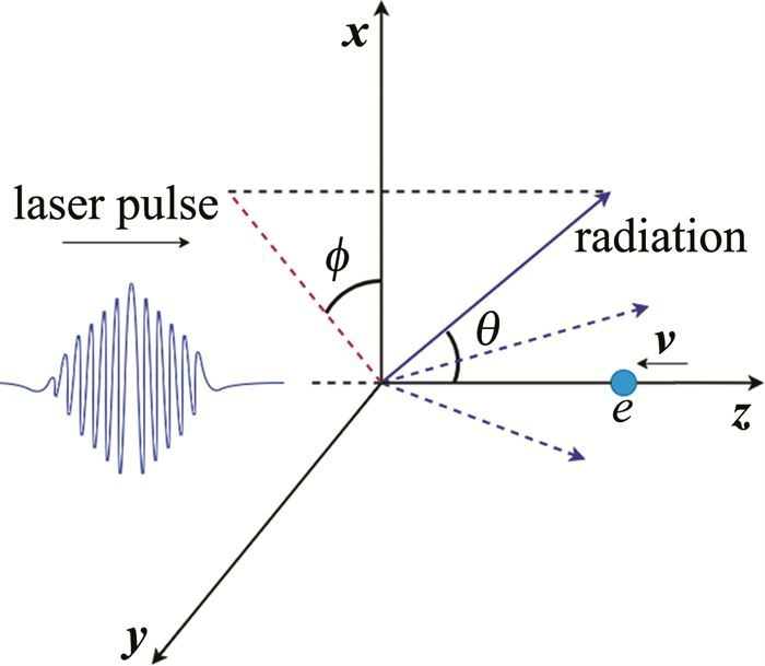
\boldsymbol{a}_z=\frac{2 a[-x \cos (\varphi+\theta)+\delta y \sin (\varphi+\theta)] \boldsymbol{z}}{b_0 b} (4) 式中,θ=π-arctan(z/zR)。椭圆偏振激光脉冲与高能电子相互作用的示意图如图 1所示。
设电子沿着-z轴方向移动,激光脉冲沿z轴正方向移动。在真空激光和单电子理论中,激光场中电场强度E=-da/dt,给出真空中单电子与激光发生碰撞运动的基本方程:
\nabla^2 \boldsymbol{a}+\mathrm{d} \boldsymbol{a} / \mathrm{d} \boldsymbol{u}=0 (5) \mathrm{d}(\boldsymbol{p}-\boldsymbol{a}) / \mathrm{d} t=-\nabla \gamma (6) \mathrm{d} \gamma / \mathrm{d} t=\boldsymbol{u} \cdot(\mathrm{d} \boldsymbol{a} / \mathrm{d} t) (7) 式中,u为电子的速度;p=γu为电子动量; γ=(1-u2)-1/2为电子能量。考虑到:
\nabla \gamma=(\boldsymbol{u} \cdot \nabla) \boldsymbol{p}+\boldsymbol{u} \times(\nabla \times \boldsymbol{a}) (8) 由于矢量势垂直于激光传播方向,电子的速度可以分解为正交分量:
\left\{\begin{array}{l} \gamma\left(\mathrm{d} u_x / \mathrm{d} t\right)=\left(1-u_x{ }^2\right)\left(\mathrm{d} a_x / \mathrm{d} t\right)-u_x u_y\left(\mathrm{~d} a_y / \mathrm{d} t\right)+u_y\left(\mathrm{~d} a_x / \mathrm{d} y-\mathrm{d} a_y / \mathrm{d} x\right) \\ \gamma\left(\mathrm{d} u_y / \mathrm{d} t\right)=\left(1-u_y{ }^2\right)\left(\mathrm{d} a_y / \mathrm{d} t\right)-u_x u_y\left(\mathrm{~d} a_y / \mathrm{d} t\right)-u_y\left(\mathrm{~d} a_x / \mathrm{d} y-\mathrm{d} a_y / \mathrm{d} x\right) \\ \mathrm{d} \gamma / \mathrm{d} t=u_x\left(\mathrm{~d} a_x / \mathrm{d} t\right)+u_y\left(\mathrm{~d} a_y / \mathrm{d} t\right) \\ \gamma=\left(1-u_x^2-u_y^2-u_z^2\right)^{-1 / 2} \end{array}\right. (9) 式中,ux,uy,uz为高能电子在坐标轴上的速度分量的大小;ax和ay为归一化矢势分量的大小。根据电动力学的知识,电子在加速运动时发射电磁辐射,由下式控制:
\frac{\mathrm{d} P(t)}{\mathrm{d} \boldsymbol{{\mathit{\Omega}}}}=\left|\frac{|\boldsymbol{n} \times[(\boldsymbol{n}-\boldsymbol{u}) \times(\mathrm{d} \boldsymbol{u} / \mathrm{d} t)]|^2}{(1-\boldsymbol{n} \cdot \boldsymbol{u})^6}\right|_{t'} (10) 式中,\frac{\mathrm{d} P(t)}{\mathrm{d} {\mathit{\Omega}}} \text { 是被 } \frac{e^2 \omega_0^2}{4 {\rm{ \mathsf{π} }} c}归一化的单位立体角辐射功率; n为辐射方向; du/dt为电子的加速度。电子辐射方向在笛卡尔坐标系中可以表示为:
\boldsymbol{n}=\sin \theta \cos \phi \cdot \boldsymbol{x}+\sin \theta \sin \phi \cdot \boldsymbol{y}+\cos \theta \cdot \boldsymbol{z} (11) 式中,θ和ϕ分别表示与激光运动方向的夹角和垂直于碰撞方向的平面上的偏转方位角。此外,Δt为发生碰撞时刻t与观察到碰撞现象时刻t'之间的时间间隔。
\Delta t=t-t^{\prime}=S_0-\boldsymbol{n} \cdot \boldsymbol{r} (12) 式中,S0表示观测点距离碰撞中心的距离,r为电子位置矢量。
通过上述方程能够得到脉冲激光和高能电子作用的过程中能量和功率随观测角的变化情况。
2. 数值模拟结果
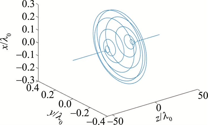
通过MATLAB软件计算来对高能电子与强激光场脉冲对撞过程中的电子轨迹进行迭代运算和模拟,得到电子在空间坐标系下的运动状态图,如图 2所示。对于位于激光传播轴上的初始静止电子,图 2是圆偏振高斯脉冲作用于电子时,电子的运动轨迹曲线,发现在对撞过程中, 电子绕激光传播轴的运动轨迹呈现螺旋状,且沿着+z轴方向传播,电子的能量总体增益先增加,然后下降,其激光脉宽L=3λ0,束腰半径b0=3λ0,初始相位φ0=0°。
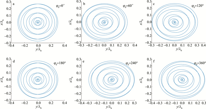
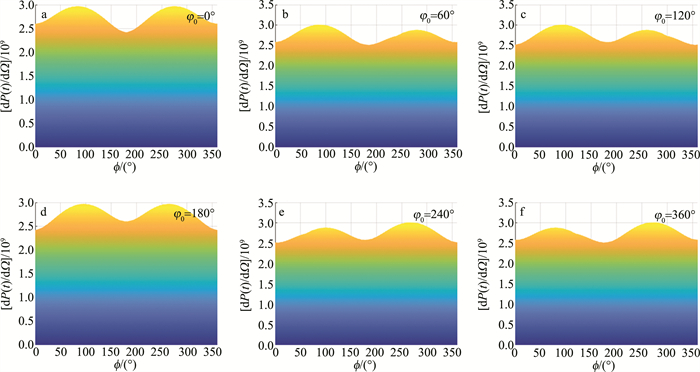
固定L和b0均取为3λ0,用不同初始相位的椭圆偏振激光器驱动,对电子的运动轨迹进行数值模拟,将所得图像沿x/λ0和y/λ0展开,得到的电子运动轨迹,如图 3所示。从图 3可以看出,高能电子的运动轨迹为1维平面对称,高能电子的运动轨迹与激光脉冲的初始相位有着较为紧密的联系。图 3中激光初始相位φ0为0°和180°时,电子的运动轨迹沿平面y=0呈直线-螺旋-直线对称图像。而图 3中其它初始相位对应电子运动轨迹不关于平面y=0对称。继续保持L和b0取值不变,利用MATLAB进行数据计算与图像处理,得到不同初始相位下激光脉冲对高能电子的辐射图像,将所得到的图像沿θ和dP(t)/dΩ展开,如图 4所示。通过图像结合数据分析可知,当激光初始相位φ0=0°时,电子最大辐射功率双峰图像关于ϕ=179.5°对称,且双峰辐射功率最大值均约为2.96970×10⁹,图 4中激光初始相位φ0=180°时,电子最大辐射功率双峰图像也呈现出双峰对称性;而当激光初始相位φ0为60°,120°,240°,300°时,双峰图像呈现出不对称性。这是由于在改变了与高能电子对撞的激光脉冲初始相位之后,电子的运动轨迹随之发生变化,导致单位立体角内的辐射功率发生改变。
从图 4还可以看出,电子最大辐射功率图随着激光初始相位的改变,呈循环态势。在初始相位φ0大于0°而小于180°期间,左峰峰值高于右峰峰值; 在φ0大于180°而小于360°期间,右峰峰值高于左峰峰值。
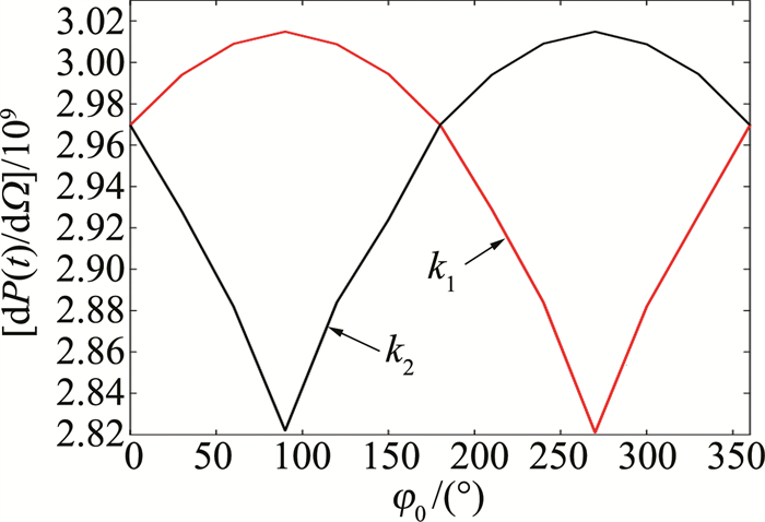
为了进一步探究电子辐射分布中两峰值数值随着激光初始相位的变化,令初始相位φ0从0°变化到360°,每隔30°记录一次数据,对不同初始相位所对应的最大辐射功率图像进行仿真,计算收集图像左右双峰的极大值,并对双峰的极大值进行比较,设最大辐射功率图像左峰极大值为k1,右峰极大值为k2,得到如图 5所示的图像。从图 5可以观察到,随着初始相位的不断增加,k1值也在增加,并在φ0=90°时增加至最大值,约为3.01490×10⁹,而后逐渐下降,在φ0=270°时取得最小值,然后继续增长,在φ0=360°时取得与0°时相同的数值,完成了一次循环。观察k1和k2数值随初始相位变化图像,不难发现其变化趋势也具有一定的对称性,且k1和k2两线交汇处表示此刻最大辐射功率图像呈现出对称型双峰。
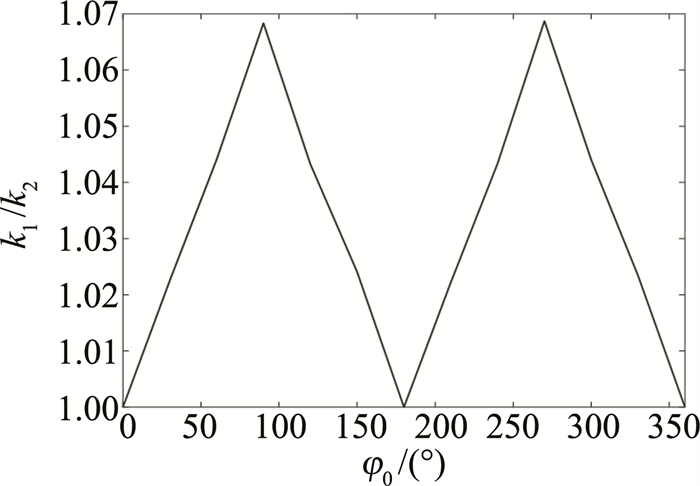
为更直观地说明图像是否对称,作者将图 5中得到的k1与k2的数值相除,得到图 6所示的图像。图 6进一步说明了当激光初始相位φ0为0°,180°和360°时,k1/k2的比值约为1,即双峰数值近乎相等,电子最大辐射功率图像呈现出对称型双峰,而在其它初始相位下呈现出非对称型双峰。
3. 结论
根据Lorentz方程与电子能量方程构造高能电子与强激光场的对撞模型,利用控制变量法,改变超短超强椭圆激光脉冲初始相位。利用MATLAB软件进行数值模拟,探究超短超强椭圆激光脉冲驱动高能电子辐射的影响,结果表明,当激光脉冲撞击电子时,电子产生辐射,且辐射功率呈现双峰形; 高能电子的辐射功率图像在激光初始相位φ0为0°,180°和360°时表现为对称型双峰, 而在其它相位下辐射功率图像呈现出非对称形双峰。此发现为超短超强椭圆偏振激光的初始相位3维反探测研究提供了一定的基础,即可以通过高能电子辐射功率的空间分布来探测出激光脉冲的初始相位。
-
表 1 H13钢材料的主要化学成分
Table 1 Main chemical composition of H13 steel material
element Cr C Mo V Si Mn Ni P S Fe mass fraction 0.05 0.0042 0.0127 0.0088 0.0089 0.003 0.016 0.0021 0.0008 balance 表 2 Ni50A材料的主要化学成分
Table 2 Main chemical composition of Ni50A
element Cr Fe B Si C Ni mass fraction 0.12 0.05 0.038 0.03 0.005 balance 表 3 WC材料的主要化学成分
Table 3 Main chemical composition of WC
element Fe C Cr V W mass fraction 0.22 0.15 0.035 0.001 balance 表 4 不同涂层中硬质相共晶化合物W元素与Cr元素含量
Table 4 Content of W and Cr in hard phase eutectic compounds in different coatings
type mass fraction of W mass fraction of Cr single-layer 0.534 0.315 double-layer 0.417 0.273 gradient 0.386 0.259 -
[1] XU J S, ZHANG X C, XUAN F Z, et al. Rolling contact fatigue behavior of laser cladded WC/Ni composite coating[J]. Surface & Coatings Technology, 2014, 239: 7-15.
[2] 李福泉, 冯鑫友, 陈彦宾. WC含量对WC/Ni60A激光熔覆层微观组织的影响[J]. 中国激光, 2016, 43(4): 0403009. https://www.cnki.com.cn/Article/CJFDTOTAL-JJZZ201604017.htm LI F Q, FENG X Y, CHEN Y B. Influence of WC content on microstructure of WC/Ni60A laser cladding layer[J]. Chinese Journal of Lasers, 2016, 43(4): 0403009(in Chinese). https://www.cnki.com.cn/Article/CJFDTOTAL-JJZZ201604017.htm
[3] 李嘉宁, 刘科高, 张元彬, 等. 激光熔覆技术及应用[M]. 北京: 北京工业出版社, 2015: 109-110. LI J N, LIU K G, ZHANG Y B, et al. Laser cladding technology and application[M]. Beijing: Beijing Industry Press, 2015: 109-110(in Chinese).
[4] SHU D, LI Z G, ZHANG K, et al. In situ synthesized high volume fraction WC reinforced Ni-based coating by laser cladding[J]. Materials Letters, 2017, 195: 178-181. DOI: 10.1016/j.matlet.2017.02.076
[5] ZHIKUN W, AIHUA W, XUHAO W, et al. Wear resistance of diode laser-clad Ni/WC composite coatings at different temperatures[J]. Surface & Coatings Technology, 2016, 304: 283-292.
[6] LEE C, PRAK H, YOO J, et al. Residual stress and crack initiation in laser clad composite layer with Co-based alloy and WC + NiCr[J]. Applied Surface Science, 2015, 345: 286-294. DOI: 10.1016/j.apsusc.2015.03.168
[7] SHI Y, LI Y, LIU J, et al. Investigation on the parameter optimization and performance of laser cladding a gradient composite coating by a mixed powder of Co50 and Ni/WC on 20CrMnTi low carbon alloy steel[J]. Optics & Laser Technology, 2018, 99: 256-270.
[8] MA Q Sh, LI Y J, WANG J, et al. Microstructure evolution and growth control of ceramic particles in wide-band laser clad Ni60/WC composite coatings[J]. Materials & Design, 2016, 92: 897-905. DOI: 10.11901/1005.3093.2016.252
[9] 吴鹏飞. 激光熔覆修复垃圾粉碎机刀盘工艺研究[D]. 广州: 广东工业大学, 2019: 46-48. WU P F. Research on laser cladding repairing cutter pulverizer[D]. Guangzhou: Guangdong University of Technology, 2019: 46-48(in Chinese).
[10] SONG L J, ZENG G Ch, XIAO H, et al. Repair of 304 stainless steel by laser cladding with 316L stainless steel powders followed by laser surface alloying with WC powders[J]. Journal of Manufacturing Processes, 2016, 24: 116-124. DOI: 10.1016/j.jmapro.2016.08.004
[11] ZHOU Sh F, LEI J B, DAI X Q, et al. A comparative study of the structure and wear resistance of NiCrBSi/50 wt% WC composite coatings by laser cladding and laser induction hybrid cladding[J]. Journal of Refractory Metals and Hard Materials, 2016, 60: 17-27. DOI: 10.1016/j.ijrmhm.2016.06.019
[12] LV Y H, LI J, TAOY F, et al. High-temperature wear and oxidation behaviors of TiNi/Ti2Ni matrix composite coatings with TaC addition prepared on Ti6Al4V by laser cladding[J]. Applied Surface Science, 2017, 402: 478-494. DOI: 10.1016/j.apsusc.2017.01.118
[13] 游川川, 肖华强, 任丽蓉, 等. TC4表面激光熔覆Ti-Al-N复合涂层的组织与性能[J]. 激光技术, 2021, 45(5): 585-589. DOI: 10.7510/jgjs.issn.1001-3806.2021.05.008 YOU Ch Ch, XIAO H Q, REN L R, et al. Microstructure and properties of laser cladding Ti-Al-N composite coating on TC4 surface[J]. Laser Technology, 2021, 45(5): 585-589(in Chinese). DOI: 10.7510/jgjs.issn.1001-3806.2021.05.008
[14] 吴祖鹏. Ni60A合金激光熔覆裂纹气孔控制方法研究[D]. 大连: 大连理工大学, 2019: 41-43. WU Z P. Study on crack and porosity control methods of laser cladding Ni60A alloy coating[D]. Daliang: Dalian University of Technology, 2019: 41-43(in Chinese).
[15] 陈子豪, 孙文磊, 黄勇, 等. 镍基高温合金激光熔覆涂层组织及性能研究[J]. 激光技术, 2021, 45(4): 441-447. DOI: 10.7510/jgjs.issn.1001-3806.2021.04.006 CHEN Z H, SUN W L, HUANG Y, et al. Study on microstructure and properties of laser cladding coating for base superalloy[J]. Laser Technology, 2021, 45(4): 441-447(in Chinese). DOI: 10.7510/jgjs.issn.1001-3806.2021.04.006
[16] JO T S, LIM J H, KIM Y D. Dissociation of Cr-rich M23C6 carbide in alloy 617 by severe plastic deformation[J]. Journal of Nuclear Materials, 2010, 406(3): 360-364.
[17] IMURAI S, THANACHAYANONTT C, PEARCE J, et al. Effects of W on microstructure of as-cast 28wt%Cr-2.6wt%C-(0-10)wt%W irons[J]. Materials Characterization, 2015, 99: 52-60.
[18] HIROTA K, MITANI M K, YAMAGUCHI O. Simultaneous synthesis and consolidation of chromium carbides (Cr3C2, Cr7C3 and Cr23C6) by pulsed electric-current pressure sintering[J]. Materials Science and Engineering, 2005, A399(1/2): 154-160.
[19] WANG D, ZHANG J, LOU L H. Formation and stability of nano-scaled M23C6 carbide in a directionally solidified Ni-base superalloy[J]. Materials Characterization, 2009, 60 (12): 1517-1521.


 下载:
下载:
