
Effect of scanning speed on the properties of laser cladding nickel-based alloy coating
-
摘要: 为了提高材料表面强度和硬度,在材料的表面采用激光熔覆技术熔覆合金涂层以提高其表面性能。相同的激光功率下采用不同的激光扫描速率在材料表面激光熔覆制备镍基(Ni60)复合涂层,取得了在基材表面获得理想熔覆层的工艺参量,并对熔覆层的性能进行了检测。结果表明,随着激光扫描速率的增加,表面粗糙度变大,熔覆层的宽度、高度、基材的熔化深度都有一定程度的降低,裂纹出现增大趋势,熔覆层显微硬度高出基材显微硬度约500HV,激光熔覆技术在一定范围内可以实现对基材的表面硬化。该结果为材料表面强化的研究提供了参考。Abstract: In order to improve the surface strength and hardness of the material, laser cladding technology was used to clad the alloy coating on the surface of the material to improve its surface properties. Nickel-based (Ni60) composite coating was prepared by laser cladding on the surface of material under the same laser power at different laser scanning speeds, and the processing parameters for obtaining the ideal cladding layer on the surface of the substrate were obtained. The properties of the cladding layer were detected. The results show that, with the increase of the laser scanning rate, the surface roughness becomes larger, the width, height of cladding layer and the melting depth of the substrate are reduced to a certain extent. The cracks appear to increase. The microhardness of the cladding layer is about 500HV higher than that of the substrate. The laser cladding technique can realize the hardening of substrate surface in a certain range. The results provide a reference for the study of surface strengthening of materials.
-
Keywords:
- laser technique /
- micro hardness /
- scanning speed /
- nickel-based alloy
-
引言
垂直腔半导体光器件具备体积小、功耗低、易于集成等优点,历来受到人们的重视[1-5]。其中,垂直腔半导体光放大器(vertical cavity semiconductor optical amplifier,VCSOA)可以看作是偏置在阈值电流以下(但非常接近)工作的激光器,它可以对入射光进行法布里-珀罗(Fabry-Perot, F-P)放大。前期的研究工作表明,作为光放大器,入射端面反射率对VCSOA的增益以及饱和输出特性有重要影响;应用于慢光时,VCSOA的时延带宽积也与入射端面反射率密切相关。因此在VCSOA设计制作中,准确控制其端面反射率,对于优化VCSOA在不同应用中的性能,是至关重要的[6-10]。
VCSOA中由多层高、低折射率交替的膜堆构成的分布布喇格反射器(distributed Bragg reflector,DBR)来提供光反馈,DBR膜堆结构决定了它的端面反射率。正入射条件下,DBR的反射率是易于计算的。但是,VCSOA腔长很短,入射到DBR上的很大一部分光是不满足正入射条件的,这样正入射条件下计算出的DBR反射率必然有偏差。所以,考虑到VCSOA内部光场分布特点,本文中将结合角谱理论和传输矩阵法来计算分析VCSOA中DBR的等效反射率。从VCSOA内部发出的光,入射到DBR上的角频谱近似服从高斯分布,首先采用传输矩阵法计算各个角频谱分量的等效反射系数,然后对反射的角频谱进行傅里叶逆变换得到反射光场分布。入射光场和反射光场一旦确定, 就可以利用它们之间的耦合关系计算出等效反射率。
计算结果表明,与只考虑正入射情况相比,修正的DBR等效反射率小了2%~4%。对于激光器而言,因为制作时可以增加DBR膜堆的层数以确保高的反射率,降低器件阈值电流,所以正入射计算误差并未引起人们的重视。但是对于放大器而言,出发点不再是降低器件阈值电流,而需要根据不同应用需求,优化设计端面反射率的大小,这样,准确计算膜堆层数对DBR等效反射率的影响就成为前提条件,这正是作者工作的动机和出发点[11-16]。
1. 理论模型
1.1 反射率的计算
VCSOA的微腔结构的形式是用高折射率层与有源区相邻,再接以低折射率层组成一个HL周期,两侧分别连接m个和n个周期,最后再接一个H层结束,形成(HL)(HL)…(HL)H结构,这种结构简称为HLH结构[17],如图 1所示。
根据光学薄膜原理,多层介质膜第j层的特征矩阵Mj为[18]:
{\mathit{\boldsymbol{M}}_j} = \left[ \begin{array}{l} \cos {\delta _j}\;\;\;\frac{{\rm{i}}}{{{\eta _j}}}\sin {\delta _j}\\ {\rm{i}}{\eta _j}\sin {\delta _j}\;\;\cos {\delta _j} \end{array} \right] (1) 式中,λ是光波波长,dj为该层厚度,nj为该层折射率,θj为入射角度,i为虚数单位, δj=2π/(λnjdjcosθj),ηj对于p偏振时为ηj=nj/cosθj,对于s偏振是ηj=njcosθj。本文中所用的薄膜厚度为1/4波长, 即dj=λ/4。整个DBR的传输矩阵M为:
\mathit{\boldsymbol{M = }}{\left( {{\mathit{\boldsymbol{M}}_{\rm{H}}}{\mathit{\boldsymbol{M}}_{\rm{L}}}} \right)^m}{\mathit{\boldsymbol{M}}_{\rm{H}}} (2) 式中,m表示DBR结构周期。
\left[ \begin{array}{l} \mathit{\boldsymbol{B}}\\ \mathit{\boldsymbol{C}} \end{array} \right] = \mathit{\boldsymbol{M}}\left[ \begin{array}{l} \;\;1\\ {\eta _{k + 1}} \end{array} \right] (3) 式中,k+1层为衬底层,B和C分别为膜层和基板的组合特征矩阵。
于是可以得到DBR多层介质膜的等效导纳Y=C/B, 则膜系的Fresnel反射系数r和反射率R为:
r = \frac{{{\eta _0} - Y}}{{{\eta _0} + Y}} (4) R = \left( {\frac{{{\eta _0} - Y}}{{{\eta _0} + Y}}} \right){\left( {\frac{{{\eta _0} - Y}}{{{\eta _0} + Y}}} \right)^*} (5) 式中,*表示共轭。利用这种方法,可以得到注入光的DBR等效反射率。
在VCSOA中有源腔内,光以一定的角度θ0入射到DBR面上[17], 如图 2所示。
入射场角频谱Fi(s)可以认为服从标准高斯分布:
{F_{\rm{i}}}\left( s \right) = A\exp \left[ { - \frac{1}{2}{{\left( {\frac{s}{{{\sigma _0}}}} \right)}^2}} \right] (6) 式中,A为高斯函数的幅值,s=sinθ0,θ0是入射角。该分布的半峰全宽(full width at half maxima,FWHM)σ定义为幅度降低一半时对应的s,即{s_{{\rm{FWHM}}}} = \sqrt {2\ln 2} {\sigma _0} =1.1774σ0, σ0为正态分布的方差。则对应θ0的θFWHM=2arcsin(sFHWM)= 2arcsin(1.1774σ0)。
对(6)式进行傅里叶逆变换, 得到入射光场分布:
{E_{\rm{i}}}\left( x \right) = A\frac{1}{{\sqrt {2{\rm{ \mathit{ π} }}} }}{\sigma _0}\exp \left( { - \frac{1}{2}{\sigma _0}^2{x^2}} \right) (7) 根据菲涅耳反射定律,反射场的角频谱Fref(s)为:
{F_{{\rm{ref}}}}\left( s \right) = r\left( {{\theta _0}} \right){F_{\rm{i}}}\left( s \right) (8) 式中,r(θ0)为菲涅耳反射系数。
对Fref(s)进行傅里叶逆变换, 得到z=0处的反射场Eref(x)。
反射场Eref(x)和入射场Ei(x)相干叠加,耦合系数的平方的比就是反射率R[19-20]:
R = \frac{{{{\left| {\smallint _{ - \infty }^\infty {E_{\rm{i}}}\left( x \right){E_{{\rm{ref}}}}\left( x \right){\rm{d}}\mathit{x}} \right|}^2}}}{{{{\left| {\smallint _{ - \infty }^\infty E_{\rm{i}}^2\left( x \right){\rm{d}}x} \right|}^2}}} (9) 1.2 半值谱宽θFHWM的判定
光波在DBR处被反射,同时一部分向自由空间输出, 如图 3所示。
输出光场的角频谱Fo(s)为:
{F_{\rm{o}}}\left( s \right) = t\left( {{\theta _0}} \right){F_{\rm{i}}}\left( s \right) (10) 式中,t(θ0)为菲涅耳透射系数。
从参考文献[16]中知道,一般半导体激光器的出光孔径为2μm~17μm时,远场扩散角度的半值谱宽为30°~7°。而对于垂直腔激光放大器,出光孔径更小,为1μm左右。远场扩散角的半值谱宽为40°左右。图 4中给出了远场扩散角的半值谱宽为38°时的内外角频谱分布图,纵坐标为相对值。由点线模拟结果可以知道,此时腔内角频谱Fi(s)的半值谱宽θFWHM=12°,σ0=0.09。拟合出来的结果与韩国公司生产的型号为RayCan RC32xxx1-Fd的光器件完全一致。
2. 分析与计算
表 1为各膜层折射率。图 5中给出了在正入射的情况下,利用传输矩阵法计算出的GaAs/AlAs结构的DBR反射率随周期数变化曲线。从图中可以看出, 随着DBR结构周期数的增加,腔反射率逐渐增加。VCSOA的一个DBR作为出光面,既要保证有一定的腔反射率用于形成谐振,又要使激射波长有一定的腔透射率用于形成激光输出;而另一个面作为反射面,主要考虑增大反射率从而使腔内有更高的增益。所以一般VCSOA的双层DBR结构并不对称。当结构周期大于25时,中心激射波长处的反射率接近1,并且基本已经不再随周期增大而改变,所以VCSOA反射面的DBR周期一般选取为25左右。而出光面的周期则既要考虑谐振,又要考虑激射波长,因而需要适当地选取。通常此类VCSOA产品出光面的DBR周期选为13。
Table 1. Refractive indexVCSOA refractive index DBR(GaAs) 3.45 DBR(AlAs) 2.89 active area (InAs0.5P0.5) 3.36 active area (In0.8Ga0.2P) 3.30 active area (InP) 3.17 base area (GaAs) 3.45 图 6中给出了考虑光场分布时,采用角频谱分析法计算出的反射率随着DBR结构周期的变化关系曲线。从计算结果可以看出,VCSOA中DBR等效反射率和光场分布有一定的关系。在一定的光场分布下,等效反射率的变化趋势和正入射时利用传输矩阵法的结果是一致的。等效反射率都随着结构周期增加而增加,且当DBR结构周期大于25时基本不再增长。在以上的分析中,作者已经提到本文中VCSOA中入射到DBR上角频谱分布的半值谱宽θFWHM一般在12°左右。图 7中给出了两者的对比情况。可以看出,当腔内角频谱分布的半值谱宽θFWHM为12°时,在同一结构周期下,VCSOA中DBR的等效放射率要比直接利用正入射的模型计算小2%~4%。这在分析VCSOA工作特性时是至关重要的。图 6中还给出了θFWHM为8°和16°时,等效反射率随结构周期的变化情况。
![Figure 7. Relationship between reflectivity and periodicity of DBR under θFWHM=12° and normal incidence]() Figure 7. Relationship between reflectivity and periodicity of DBR under θFWHM=12° and normal incidence
Figure 7. Relationship between reflectivity and periodicity of DBR under θFWHM=12° and normal incidence图 8中给出了DBR等效反射率随光场分布的关系。在同一结构周期下,等效反射率在正入射θFWHM=0°时最大,并随着θFWHM变大而逐渐降低。从图中看出, 当光场分布比较集中(θFWHM < 8°)时,等效反射率和正入射时相当。(结构周期为13时,等效反射率为0.985)。此时的光相当于正入射到DBR上,光场失谐不大,对等效反射率影响较小。随着半值谱宽增加,入射场和反射场的失谐程度越大,等效反射率越低。考虑光场分布的影响后,同一结构周期的等效反射率降低了2%~4%。当周期为13、且θFWHM=12°时,等效反射率R=0.97。当腔内光场分布更不集中的情况下,等效反射率更低。
3. 结论
本文中利用角频谱分析法,结合传输矩阵计算了VCSOA中DBR的等效反射率。等效反射率随着结构周期增加而变大,但是当周期大于25时基本不再变化。分析了等效反射率和光场分布的关系。在同一结构周期下,考虑光场分布时的等效反射率和正入射变化趋势相同,但是要小2%~4%。等效反射率随着半值谱宽θFWHM增大而减小。这为准确计算膜堆层数对DBR等效反射率的影响提供了理论指导,可进一步优化VCSOA的工作性能,例如降低阈值、优化增益带宽积等。
-
![]()
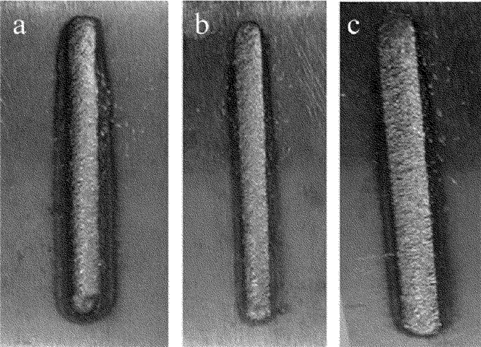
Figure 1. Macroscopic morphology of single channel cladding surface at diffe-rent laser scanning speeds
a-2mm/s b-4mm/s c-6mm/s
![]()
Figure 2. Macroscopic morphology of multi-channel cladding surface at diffe-rent laser scanning speeds
a-2mm/s b-4mm/s c-6mm/s
![]()
Figure 4. SEM morphology of cladding layer at different laser scanning speeds
a-2mm/s b-4mm/s c-6mm/s
Table 1 Chemical composition (mass fraction) of 45# steel matrix
C Si Mn Cr Ni Cu P, Fe 0.005 <0.002 <0.001 ≤ 0.001 <0.001 ≤ 0.001 balance  下载: 导出CSV
Table 2 Chemical composition (mass fraction) of Ni60 alloy powder
Si C Fe B Cr Ni 0.008 0.001 0.003 0.031 0.003 balance
下载: 导出CSV
Table 3 Process parameters of laser cladding
laser
power/
kWspot
diameter/
mmpulverized
speed/
(g·s-1)scanning
speed/
(mm·s-1)lap
rate/
%defocus/
mm1.4 2 1.2 2, 3, 4 50 16
下载: 导出CSV
-
[1] ZHANG A F, LI D Ch, LIANG Sh D. Development of laser additive manufacturing of high-performance metal parts[J]. Aeronautical Manufacturing Technology, 2016, 59(22):16-22(in Chinese). http://www.en.cnki.com.cn/Article_en/CJFDTotal-HKGJ201622003.htm
[2] ZHONG M L, NING G Q, LIU W J. Research and development on laser direct manufacturing metallic components[J].Laser Technology, 2002, 26(5):388-391(in Chinese). http://www.wanfangdata.com.cn/details/detail.do?_type=perio&id=jgjs200205003
[3] HUANG W D, LIN X, CHEN J, et al. Laser solid forming[M]. Xi'an:Northwestern Polytechnical University Press, 2007:2-3(in Chinese).
[4] ZHENG B J, WEI J Y, JIANG Y H, et al. Wear property of NiCoFeCrTi high entropy alloy coating by laser cladding[J]. Laser Technology, 2016, 40(3):432-435(in Chinese). http://www.wanfangdata.com.cn/details/detail.do?_type=perio&id=jgjs201603028
[5] LI Sh Y, TIAN X G, LI Ch B. Study on wear-resistance and scanning path of laser alloying on end cap working face[J]. Chinese Journal of Lasers, 2013, 40(2):0203004(in Chinese). DOI: 10.3788/CJL
[6] SONG J L, LI Y T. Research progress on laser cladding forming technology[J].Journal of Mechanical Engineering, 2010, 46(14):29-39(in Chinese). DOI: 10.3901/JME.2010.14.029
[7] LIU F R, GAO Q, GAO D P. Cracking analysis of WC reinforced composites coating by laser cladding[J]. Journal of Material Engineering, 2003, 31(5):37-39(in Chinese). http://www.wanfangdata.com.cn/details/detail.do?_type=perio&id=clgc200305010
[8] YAO J H. Laser surface modification technology and application[M].Beijing:National Defense Industry Press, 2012:59-61(in Ch-inese).
[9] ZOU X B, YIN D K, GU J J. A study on the cracks in laser cladding[J]. Laser Journal, 2010, 31(5):44-45(in Chinese).
[10] RONG L R. Laser cladding technology and application of[J]. Me-tal Processing, 2012, 63(15):37-39(in Chinese). http://d.old.wanfangdata.com.cn/Periodical/cldb2018z1074
[11] SHEN B, YAN G Ch, WU G. Laser cladding on complex disc cam[J]. Chinese Journal of Lasers, 2009, 36(1):244-248(in Chin-ese). DOI: 10.3788/JCL
[12] ZHU G X, ZHANG A F, LI D Ch. Effect of process parameters on surface smoothness in laser cladding[J]. Chinese Journal of Lasers, 2010, 37(1):296-301(in Chinese). DOI: 10.3788/JCL
[13] LI Y L, BAI X B, WANG L, et al. Impact of laser cladding process parameters on the microstructure and properties of the cladding layer[J].Thermal Processing, 2009, 38(12):101-103(in Chinese).
[14] ZHANG S Y, ZHENG K Q, ZHENG L. Influence of scanning speed on microstructure and properties of laser cladding WC-B4C-Co coating[J]. Chinese Journal of Lasers, 1993, 20(12):940-943(in Ch-inese). http://en.cnki.com.cn/Article_en/CJFDTOTAL-JJZZ199312015.htm
[15] SHI Sh H, LI B W. Influence of laser cladding process and powder on the cracking behavior of cladding[J].Laser Journal, 1998, 19(3):46-48(in Chinese).
[16] ZHANG D Q, ZHANG J Q, GUO Zh J. Study on microstructure and properties of laser cladding repair 45# steel mould[J]. Mechanical Design and Manufacture, 2017, 2(2):118-120(in Chinese). http://www.sciencedirect.com/science/article/pii/S1359836816331134
[17] LU W. Study on the cracking of the roll cladding layer of laser cladding high speed wire[D]. Beijing: Beijing University of Technology, 2006: 8-10(in Chinese).
[18] ENDRZEJEWSKI R, SLIWINSKI G, KRAWCZUK M. Temperature and stress during laser cladding of double layer coatings[J].Surface and Coatings Technology, 2006, 201(6):3328-3334. DOI: 10.1016/j.surfcoat.2006.07.065
[19] ZHANG Ch Ch, SHI Y. Research status and development trend of laser cladding high thickness coating technology[J]. Laser Techno-logy, 2011, 35(4):448-452(in Chinese).


计量
- 文章访问数: 4
- HTML全文浏览量: 1
- PDF下载量: 5