Advanced Search

ISSN1001-3806 CN51-1125/TN Map

Volume 48 Issue 2
Mar.  2024
Article Contents
Turn off MathJax

Citation:

Study on luminance accurate measurement method based on imaging spectrometer

  • Corresponding author: ZENG Yan'an, 79844404@qq.com
  • Received Date: 2023-01-13
    Accepted Date: 2023-02-27
  • To achieve fast and accurate measurement of the luminance of flat-panel displays, an imaging spectrometer based on linear variable filters was used for theoretical analysis and experimental validation. The principle, structure, and application characteristics of the imaging spectrometer with linear variable filters as the core was discussed and a mathematical conversion model of light source luminance-output grayscale value was established. A spectral calibration and radiation calibration device based on an LED integrating sphere light source and a spectroradiometer was developed, and the spectral cube data of the target was obtained, along with the absolute spectral power distribution curve of each point. The results show that the relative display error is less than 3%, meeting the first-level measurement accuracy requirement of the national standard for luminance measurement. The rapid and accurate measurement of surfece light source luminance is realized. This study provides a favorable reference for optimizing the quality control and product adjustment of the display industry.
  • 加载中
  • [1] 江文杰, 曾学文, 施建华. 光电技术[M]. 北京: 科学出版社, 2009: 184-228.

    JIANG W J, ZENG X W, SHI J H. Optical technology[M]. Beijing: Science Press, 2009: 184-228(in Chinese).
    [2] 全国光学计量技术委员会. 亮度计检定规程: JJG 211-2021[S]. 北京: 中国质检出版社, 2022: 1-4.

    NATIONAL OPTICAL METROLOGY TECHNICAL COMMITTEE. Verification regulation of luminance meter: JJG 211-2021[S]. Beijing: China Quality Inspection Press, 2022: 1-4(in Chinese).
    [3]

    TSIRKEL A M, BRADSKI G R, DAVIES R L. Method and apparatus to adjust the brightness of a display screen: US, 20030122810A1[P]. 2003-07-02.
    [4] 张雪静, 徐英莹, 曹峰梅. 两种不同类型的滤光片式彩色亮度计性能比较[J]. 液晶与显示, 2013, 28(1): 146-151.

    ZHANG X J, XU Y Y, CAO F M. Performance contrast of two diffe-rent types of optical filter color luminance meter[J]. Chinese Journal of Liquid Crystals and Displays, 2013, 28(1): 146-151(in Chin-ese).
    [5] 陈洁昌. 基于彩色图像传感器的LED显示模组亮度与色度测量研究[D]. 厦门: 厦门大学, 2019: 14-31.

    CHEN J Ch. Research on the luminance and chroma measurement of LED display assembly based on color image sensors[D]. Xiamen: Xiamen University, 2019: 14-31(in Chinese).
    [6]

    SCZUPAK R, FREDELL M, UPTON T, et al. Measurement and alignment of linear variable filters[J]. Proceedings of the SPIE, 2018, 10539: 105390Y.
    [7]

    ZHOU Sh, SONG Sh G, CAI S J, et al. Development of measurement system and analysis method for characterization of linear variable bandpass filters[J]. Optics Express, 2021, 29(14): 21386-21399. doi: 10.1364/OE.431571
    [8] 王颖, 巩岩. 线性渐变滤光片型多光谱成像光谱仪设计[J]. 激光与光电子学进展, 2016, 53(1): 013003.

    WANG Y, GONG Y. Design of multispectral imaging spectrometer using linear variable filter[J]. Laser & Optoelectronics Progress, 2016, 53(1): 013003(in Chinese).
    [9] 李洪波. 基于线性渐变滤光片的光谱成像技术研究[D]. 西安: 中国科学院西安光学精密机械研究所, 2018: 28-30.

    LI H B. Study of imaging hyperspectral technique based on linear va-riable filter[D]. Xi'an: Xi'an Institute of Optics and Precision mechanics of CAS, 2018: 28-30(in Chinese).
    [10]

    RICHARD I S, BASIL L S, RICHARD J R, et al. Method of making a monolithic linear variable filter and method of manufacture: US, 5872655A[P]. 1999-02-16.
    [11] 薛庆生, 李畅, 李婷婷, 等. 基于LVF的高光谱成像仪研制及应用[J]. 光子学报, 2021, 50(9): 0911001.

    XUE Q Sh, LI Ch, LI T T, et al. Development and application of hyperspectral imager based on LVF[J]. Acta Photonica Sinica, 2021, 50(9): 0911001(in Chinese).
    [12]

    RAHMLOW T D, COTE W, JOHNSON R L. Hyperspectral imaging using a linear variable filter (LVF) based ultra-compact camera[J]. Proceedings of the SPIE, 2020, 11287: 1128715.
    [13]

    MURR P J, WIESENT B R, HIRTH F, et al. Thin film measurement system for moving objects based on a laterally distributed linear variable filter spectrometer[J]. Review of Scientific Instruments, 2012, 83(3): 035110. doi: 10.1063/1.3697750
    [14] 陈均溢. 数字相机性能参数测量系统设计与实现[D]. 武汉: 华中科技大学, 2020: 17-20.

    CHEN J Y. Measurement and analysis of absolute spectral response efficiency of photoelectric imaging system[D]. Wuhan: Huazhong University of Science and Technology, 2020: 17-20(in Chinese).
    [15] 秦莉, 董丽丽, 许文海, 等. CCD图像灰度与照度的转换标定方法[J]. 仪器仪表学报, 2015, 36(3): 639-644.

    QIN L, DONG L L, XU W H, et al. Method for conversion calibration between CCD image gray value and illumination[J]. Chinese Journal of Scientific Instrument, 2015, 36(3): 639-644(in Chin-ese).
    [16] 张以谟, 张红霞, 贾大功. 应用光学[M]. 第4版. 北京: 电子工业出版社, 2015: 112-116.

    ZHANG Y M, ZHANG H X, JIA D G. Applied optics[M]. 4th ed. Beijing: Publishing House of Electronics Industry, 2015: 112-116(in Chinese).
    [17]

    EUROPEAN MACHINE VISION ASSOCIATION. EMVA standard: 1288[S]. Berlin, Germany: European Machine Vision Association, 2016: 1-5.
    [18] 刘洪麟. 机载高光谱成像仪光谱定标关键技术研究[D]. 上海: 中国科学院大学, 2020: 23-28.

    LIU H L. Study on the key technologies of spectral calibration for airborne hyperspectral imager[D]. Shanghai: University of Chinese Academy of Sciences, 2020: 23-28(in Chinese).
    [19] 崔燕. 光谱成像仪定标技术研究[D]. 西安: 中国科学院西安光学精密机械研究所, 2009: 34-41.

    CUI Y. The technical study of spectrometric calibration[D]. Xi'an: Xi'an Institute of Optics and Precision Mechanics of CAS, 2009: 34-41(in Chinese).
    [20] 孙立微. 空间高光谱遥感仪器辐射定标技术研究[D]. 上海: 中国科学院大学, 2018: 24-30.

    SUN L W. Research on radiometric calibration for space hyperspectral remote sensor[D]. Shanghai: University of Chinese Academy of Sciences, 2018: 24-30(in Chinese).
  • 加载中
通讯作者: 陈斌, bchen63@163.com
  • 1. 

    沈阳化工大学材料科学与工程学院 沈阳 110142

  1. 本站搜索
  2. 百度学术搜索
  3. 万方数据库搜索
  4. CNKI搜索

Figures(8) / Tables(3)

Article views(635) PDF downloads(11) Cited by()

Proportional views

Study on luminance accurate measurement method based on imaging spectrometer

    Corresponding author: ZENG Yan'an, 79844404@qq.com
  • School of Optical and Electronic Information, Huazhong University of Science and Technology, Wuhan 430074, China

Abstract: To achieve fast and accurate measurement of the luminance of flat-panel displays, an imaging spectrometer based on linear variable filters was used for theoretical analysis and experimental validation. The principle, structure, and application characteristics of the imaging spectrometer with linear variable filters as the core was discussed and a mathematical conversion model of light source luminance-output grayscale value was established. A spectral calibration and radiation calibration device based on an LED integrating sphere light source and a spectroradiometer was developed, and the spectral cube data of the target was obtained, along with the absolute spectral power distribution curve of each point. The results show that the relative display error is less than 3%, meeting the first-level measurement accuracy requirement of the national standard for luminance measurement. The rapid and accurate measurement of surfece light source luminance is realized. This study provides a favorable reference for optimizing the quality control and product adjustment of the display industry.

0.   引言
  • 光亮度的精确测量在显示屏性能评估、车灯性能以及隧道照明环境检测等领域有着广泛的应用。随着应用的不断深入,对面光源进行光亮度测量的精度要求也越来越高; 同时光亮度测量的精度也影响着色度、色域等光学参数的测量[1-3]

    目前平板显示器的光学性能测量主要采用成像式亮度计,工业成像式亮度计主要分为两类:滤光片式成像亮度计和分光光谱式成像亮度计。滤光片式成像亮度计采用特定的滤光片模拟人眼对光的响应,使得加上滤光片的图像传感器的光谱响应与基于人眼颜色视觉的国际照明委员会(Commission Internationale de L’eclairage,CIE)标准色度匹配函数相匹配,通过图像传感器输出的灰度值计算出目标各点的光亮度,具有测量速度快、体积小、应用环境广的优点,但滤光片匹配存在误差,因而测量精度不高,校准工作量大。分光光谱式成像亮度计将点式光谱仪与图像传感器相结合,利用光谱仪测量特定区域(一般是视场中心区域)的光谱辐射亮度曲线,再利用图像传感器测量目标的灰度值,由此得到目标的光亮度值,具有测量速度快、成本低、体积小等优点,但由于目标各点的光谱曲线实际上并不是相同的,因而测量精度也有限[4-5]。本文作者以显示屏光亮度高精度测量的需求为应用背景,研究了以线性渐变滤光片为核心的成像光谱仪光亮度测量方法,通过获取目标各像素点绝对辐射亮度光谱分布曲线,高精度地计算出目标各点的光亮度信息。

1.   线性渐变滤光片成像光谱仪原理
  • 以线性渐变滤光片(linear variable filter,LVF)为分光元件的成像光谱仪由光学成像镜头、线性渐变滤光片、电感耦合图像传感器(CMOS image sensor,CIS)、目标位移平台构成。LVF置于光学成像镜头与CIS之间,并紧贴CIS的探测表面[6-8],如图 1所示。

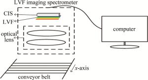
    Figure 1.  Schematic diagram of imaging spectrometer system

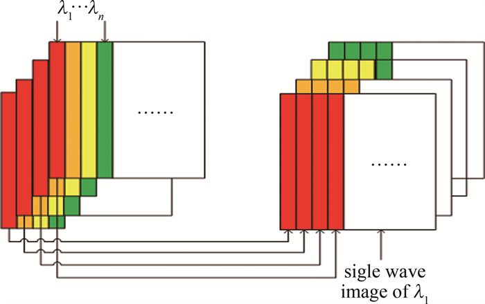
    设物体移动方向为x轴,LVF在此方向上中心波长线性变化,在垂直方向上中心波长保持不变。CIS在x轴方向上每一行像元所接收到的光谱波长都与LVF对应位置上的透过波长相对应[9],因此不同行对应不同波长的单色光谱。为了获取目标的完整光谱信息,需要改变成像光谱仪和目标的相对位置。将目标固定在传送带上,沿LVF波长变化方向匀速移动,使目标的同一行分时成像在图像传感器的不同行,分时获取目标的光谱数据,再通过图像重构得到目标的光谱信息数据立方体信息[10-12]。LVF成像光谱仪图像重构原理如图 2所示,每一帧图像都包含目标的2维空间信息和全谱段光谱信息。将对应的单波长条带依次提取进行重排拼接,即可获得特定波段的单波长图像,所有单波长图像叠加即得到待测目标的高光谱数据立方体。

    Figure 2.  Principle of spectral image reconstruction

2.   光亮度计算模型
  • 为精确测量目标的光亮度信息,需要建立待测目标面光源光亮度与图像传感器CIS输出灰度值的函数关系。根据光学系统能量传递关系,得到目标物面光谱辐射亮度与像面光谱辐射照度的传递关系,根据CIS的成像原理,得到CIS像面光谱辐射照度与CIS输出图像灰度值的传递关系,再由CIE1931亮度计算方法得到目标面光源的光亮度值[13]

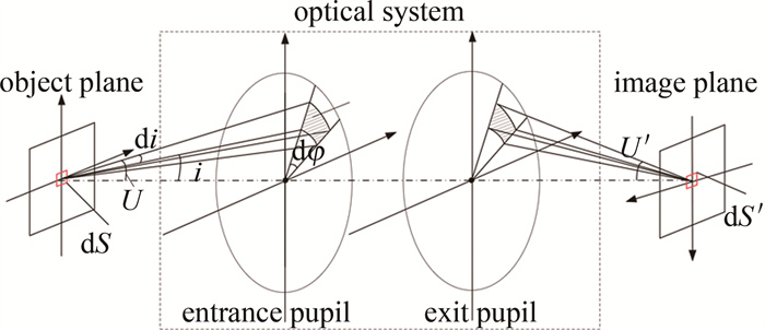
    物面上微小面元的最大孔径角由孔径光阑的大小决定,由于物面不同位置的微小面元对应的最大孔径角相同,因此进入成像光学系统的光辐射能量相同[14-15]。由于不同位置的微小面元进入光学系统的光能量都相同,因此仅分析光学系统中心的光能量传递情况,传递示意图如图 3所示。

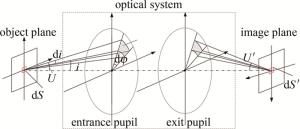
    Figure 3.  Diagram of energy transfer of optical imaging system

    将物面视为余弦辐射体,在物面取一微元dS,对应的像面微元为dS′,如图 3中剖面线扇形所示。dS与dS′可构成元光管[16],每个元光管的辐射通量为dΦ,对整个入瞳面积分,可求出从dS向整个入瞳发射的总辐射通量Φ

    由光谱辐射亮度的定义,得到波长为λ的光谱辐射通量为:

    式中:由于物面为余弦辐射面,光谱辐射亮度L(λ)为恒定值; dφ为入瞳上的光面相对入瞳中心的张角,i为入瞳相对光源的方向角; U为入瞳上光面对物面原点的张角; 定义K(λ)为透过LVF照射到CIS像元上的光谱透过率,则像面dS′接收到的光谱辐射通量为:

    可推出像面dS′处的光谱辐射照度E′(λ)为:

    式中: β为垂轴放大率。由图像传感器及成像系统原理可知[17],图像传感器像元输出灰度值u与曝光时间内该像元接收的光子数量μ为线性关系:

    式中: ud为像元在无光辐射照射下输出的暗信号; G为CIS的总增益; η为量子效率。

    像元接收的光子数量可由像元表面的光谱辐射照度值E′(λ)和曝光时间t计算得到,将式(3)代入,得到物平面像元的光谱辐射亮度L(λ):

    式中: hc/λ表示光子能量; A为图像传感器像元面积; C(λ)为光谱辐射亮度校正曲线。

    根据人眼视觉特性函数V(λ)和最大光谱光视效能Km,将辐射亮度转换为光亮度Lv

    式中: Δλ为波长间隔。

3.   定标
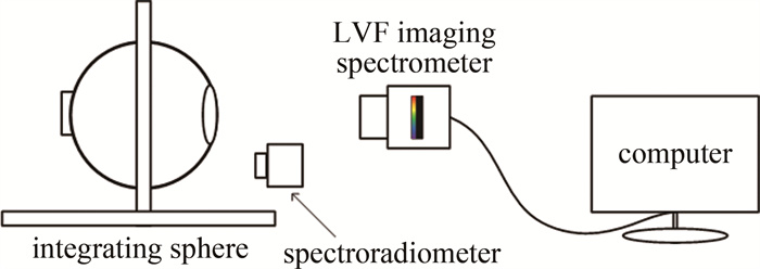
  • 通过光谱定标建立像元位置与波长之间的函数关系,通过辐射定标建立灰度值和辐亮度之间的函数关系。定标系统示意图如图 4所示,包括发光二极管积分球光源、分光光谱辐射亮度计CS-2000A、自研LVF成像光谱仪、计算机及配套软件。

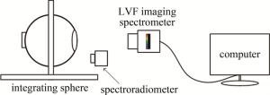
    Figure 4.  Structural diagram of the calibration system

    LVF成像光谱仪的性能参数如表 1所示,采用的分光辐射亮度计CS-2000A的性能参数如表 2所示。

    performance parameters camera parameters
    spectral range 384 nm~1050 nm detector type CMOS global shutter
    spectral resolution 2.60 nm data aquistition type continuous shooting/snapshot
    numbers of spectral channels 256 data format 8 bit, 10 bit
    CIS pixel 2048×2048 data interface USB3.0
    time of exposure 28 μs~1 s lens type F port telecentric lens

    Table 1.  LVF imaging spectrometer parameters

    performance parameters value
    wavelength range 380 nm~780 nm
    wavelength resolution 0.9 nm/pixel
    display wavelength width 1 nm
    wavelength accuracy ±0.3 nm
    spectral wave width 5 nm(full width at half maximum)

    Table 2.  CS-2000A parameters

  • LVF成像光谱仪的入射光分光后不同波长的单色光对应着图像传感器不同的像元位置,只有确定了像元位置与中心波长的函数关系,将像元与中心波长一一对应,才能在图像重构算法中拼接出单色图像,得到各像元的光谱曲线信息[18]

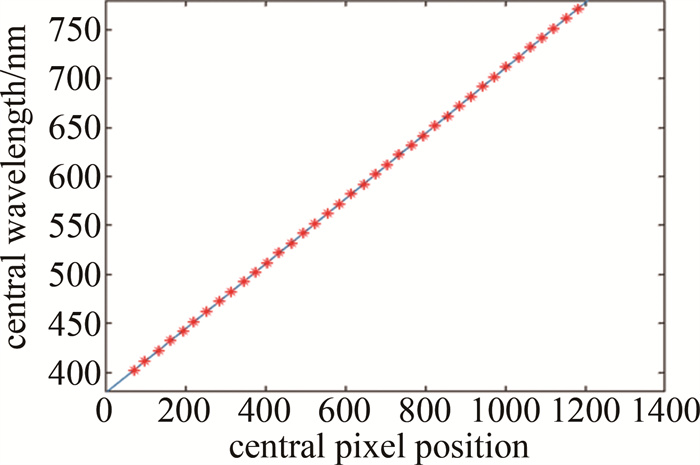
    采用特征光谱法进行光谱定标,积分球光源输出高均匀面辐射光源,用分光辐射亮度计和LVF成像光谱仪同步采集数据[19]。分光辐射亮度计得到光源的光谱辐射亮度数据,LVF成像光谱仪得到灰度值随像元位置变化的数据。在可见光范围内,将特征光谱的中心波长以固定间隔步进,分别对采集的数据进行高斯函数拟合,得到峰值点对应的中心波长与中心像素位置,基于最小二乘法建立波长和像素位置的函数对应关系。拟合图像如图 5所示。

    Figure 5.  Spectral calibration curve

    拟合得到的波长λ关于像元位置p的表达式为:

  • 由光谱辐射亮度计算公式可知,光源的光谱辐射亮度由光谱辐射亮度校正曲线C(λ)、CIS图像输出灰度值与曝光时间共同决定[20]

    使用光源控制系统控制积分球输出光源,使其输出连续光谱面光源,使用辐射亮度计采集积分球出光口的光谱辐射亮度曲线,如图 6所示。

    Figure 6.  Spectral radiance curve

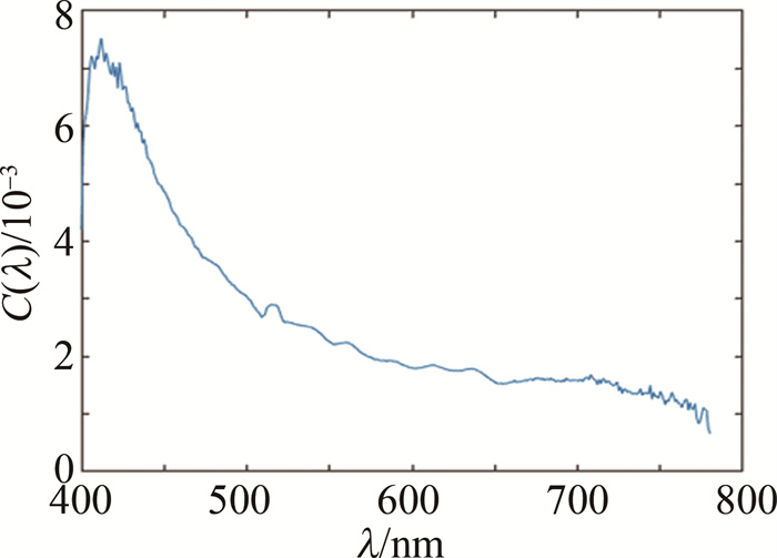
    在不同曝光时间条件下,LVF成像光谱仪分别采集暗信号和亮信号图像数据,采集多帧图像数据平均处理得到灰度值随波长变化曲线,从而计算出光谱辐射亮度校正曲线C(λ),如图 7所示。

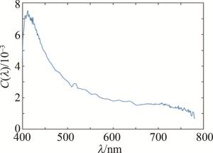
    Figure 7.  Spectral radiance correction curve

4.   光亮度测量实验
  • 将显示屏作为待测目标,根据光亮度计算模型得到不同位置的光谱辐射亮度值,以光谱分光辐射亮度计的测量结果作为标准值,对比如图 8所示。

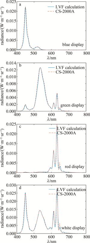
    Figure 8.  Spectral radiance curves comparison

    可以看出,在测量同一位置的辐亮度分布时,LVF成像光谱仪计算结果与光谱分光辐射亮度计的示值差异较小,波形变化趋势基本一致,系统整体测量结果较为准确。在650 nm左右,系统计算值与标准值出现了误差,LVF成像光谱仪所测辐亮度被抬高,可能是由于光路倾斜导致此波段发生了光谱混叠,从而使得650 nm对应的CIS像素位置接收到了附近波长的透射光。

    根据式(6)将辐射亮度转换为光亮度,计算出光亮度测量的相对示值误差,如表 3所示。

    luminance meter results/(cd·m-2) luminnance measurement system results/(cd·m-2) relative indication error/%
    45.274 44.032 -2.743
    100.484 98.568 -1.907
    164.285 164.096 -0.115
    205.296 206.965 0.813
    420.458 419.789 -0.159
    515.792 518.328 0.492
    587.296 591.389 0.697
    637.109 636.028 -0.170

    Table 3.  Luminance measurement results

    可见系统的亮度相对示值误差范围在-2.743%~0.813%之间,测量精度小于±3.0%。

5.   结论
  • 以显示屏的在线性能检测应用需求为背景,分析了LVF成像光谱仪的原理结构以及物面光亮度到像面输出灰度值的传递过程,并以此为基础得到了目标光亮度的计算模型; 建立了基于积分球光源、分光光谱辐射亮度计、成像光谱仪的实验定标装置,实现了测量系统的光谱定标和辐射定标; 最后进行了实际的光亮度测量和分析比较。结果表明, 本文中的测量方法和实际情况有较好的一致性,相对示值误差小于3%,达到了国标JJG 211-2021光亮度测量所规定的一级测量精度要求。目前,显示行业对于亮度计的测量要求越来越高,本文中设计的LVF成像光谱仪亮度测量系统在提供准确可靠的亮度测量的同时,系统整体结构小型精巧、测量范围广、稳定性高,能满足市场要求,可帮助提升显示屏产品质量。

Reference (20)

Catalog

    /

    DownLoad:  Full-Size Img  PowerPoint
    Return
    Return