Advanced Search

ISSN1001-3806 CN51-1125/TN Map

Volume 45 Issue 1
Jan.  2021
Article Contents
Turn off MathJax

Citation:

Fiber optical sensor demodulation research based on asymmetric 3×3 coupler

  • Corresponding author: NING Na, 13302538709@189.cn
  • Received Date: 2019-12-12
    Accepted Date: 2020-03-18
  • In the fiber optical sensor demodulation based on asymmetric 3×3 coupler, the fiber-optic median phase shift 3×3 adder due to the limitation of the manufacturing process and the susceptibility to external environmental interference, and then the three-way signal output has an uneven splitting ratio and an asymmetric phenomenon that the phase difference cannot meet 120°, which causes a problem that could not be accurately corrected. In order to solve these problems, a new 3×3 replacer was used, and theoretical analysis and experimental verification were performed. The mean two algorithms were used to pre-process any two signals output, and compressed the original three signals. The power and phase difference between the output signals of the two channels make the new three-channel signals after correction to be approximately symmetrical output, and then perform a symmetric algorithm operation. Simulation and experimental results show that the new scheme can effectively correct the asymmetry of the three output signals of the positive 3×3 converter, and classify it. Noise level of the new scheme is about 10-4mW and signal-to-noise ratio is about 50dB. Compared with the traditional alternative scheme, the new structure can obtain higher accuracy and signal-to-noise ratio of the signal under test. In addition, according to the simulation and experimental results, the symmetry conditions of the output of the replacer and the anti-noise capability of the new superposition scheme are analyzed. The result has a good guiding role in the field of optical fiber polarizers and accelerates the practical process of optical fiber sensing technology.
  • 加载中
  • [1]

    LU Y, ZHU T, CHENG L, et al. Distributed vibration sensor based on coherent detection of phase-OTDR[J]. Journal of Lightwave Technology, 2010, 28(22): 3243-3249.
    [2]

    PENG F, DUAN N, RAO Y, et al. Real-time position and speed monitoring of trains using phase-sensitive OTDR[J]. IEEE Photonics Technology Letters, 2014, 26(20): 2055-2057. doi: 10.1109/LPT.2014.2346760
    [3]

    ZHANG B, ZHANG E T, HU X Ch, et al. Amplification charactcristics of multiwavelength crbium-doped fiber laser amplifiers[J]. Laser Technology, 2018, 42(3): 325-330(in Chinese).
    [4]

    BAO X, ZHOU D P, BAKER C, et al. Recent development in the distributed fiber optic vibration and ultrasonic detection[J]. Journal of Lightwave Technology, 2016, 35(16): 3256-3267.
    [5]

    LIU Sh, HAN X Y, XIONG Y Ch. Distributed vibration detection system based on weak fiber grating array[J]. Chinese Journal of Lasers, 2017, 44(2): 0210001(in Chinese).
    [6]

    YING C. Quantitative detection of phase-demodulation techniques for phase-sensitive optical time domain reflectometry[D]. Hangzhou: Zhejiang University, 2018: 13-23(in Chinese).
    [7]

    ZHANG X, SUN Z, SHAN Y, et al. A high performance distributed optical fiber sensor based on φ-OTDR for dynamic strain measurement[J]. IEEE Photonics Journal, 2017, 9(3): 1-12.
    [8]

    XU N, DAI M. Distributed optical fiber temperature and pressure sensor design[J]. Chinese Optics, 2015, 8(4): 629-635(in Chinese).
    [9]

    LIU L. Research on light reflector based on helium pulse[D]. Shanghai: Shanghai Jiao Tong University, 2015: 17-47(in Chinese).
    [10]

    WU G X, DUAN F J. Avalanche photodiode electric heterodyne mixing technology and its parameter optimization[J]. Laser Technology, 2015, 39(6):803-804(in Chinese).
    [11]

    QIAO J P, DENG L W, HE J, et al. Optimization of fast image encryption algorithm based on chaotic mapping[J]. Laser Technology, 2017, 41(6): 897-903(in Chinese).
    [12]

    XU G, HE Ch Ch, ZHANG L N, et al. Research of position technology of Mach-Zehnder interferometer[J]. Laser Technology, 2019, 43(2): 195-200(in Chinese).
    [13]

    SU B L. Investigation on quasi-lossless transmission system based on pumping Raman amplification[J]. Laser Technology, 2017, 41(2): 265-269(in Chinese).
    [14]

    QIAN X L, KONG Y, DU T Y, et al. Study on full-sensitivity to vibration of phase sensitive optical time-domain reflectometers[J].Laser Technology, 2019, 43(5): 608-613(in Chinese).
    [15]

    CHEN K, ZHENG J Y, ZHOU J H, et al. Design of real-time fast polarization control algorithm[J]. Laser Technology, 2017, 41(5): 738-742(in Chinese).
    [16]

    KOYAMADA Y, IMAHAMA M, KUBOTA K, et al. Fiber-optic distributed strain and temperature sensing with very high measurand resolution over long range using coherent OTDR[J]. Journal of Lightwave Technology, 2009, 27(9): 1142-1146.
    [17]

    LV Y L, XING Y W. Study on rayleigh scattering waveform characteristics of phase light time domain reflectometer[J]. Acta Optica Sinica, 2011, 31(8): 0819001(in Chinese).
    [18]

    HUANG Zh H, WANG Y L, LI G F, et al. Adaptive frequency-domain equalization for few-mode fiber transmission systems[J]. Laser Technology, 2017, 41(1): 124-128(in Chinese).
    [19]

    GAO H, LIU J M, YANG Ch, et al. Compact solid-state lasers with high peak power used for remote laser rangefinders[J]. Laser Technology, 2019, 43(5): 597-600(in Chinese).
    [20]

    XU S H, XIAO Sh L. Research on reverse modulation optical communication system based on acousto-optic modulation[J]. Laser Technology, 2015, 39(5): 599-600(in Chinese).
  • 加载中
通讯作者: 陈斌, bchen63@163.com
  • 1. 

    沈阳化工大学材料科学与工程学院 沈阳 110142

  1. 本站搜索
  2. 百度学术搜索
  3. 万方数据库搜索
  4. CNKI搜索

Figures(8)

Article views(7541) PDF downloads(20) Cited by()

Proportional views

Fiber optical sensor demodulation research based on asymmetric 3×3 coupler

    Corresponding author: NING Na, 13302538709@189.cn
  • 1. Zhuhai Power Supply Bureau, Guangdong Power Grid Company, Zhuhai 519000, China
  • 2. Allian Stream Photonics Techno-logy Co. Ltd., Wuxi 214000, China

Abstract: In the fiber optical sensor demodulation based on asymmetric 3×3 coupler, the fiber-optic median phase shift 3×3 adder due to the limitation of the manufacturing process and the susceptibility to external environmental interference, and then the three-way signal output has an uneven splitting ratio and an asymmetric phenomenon that the phase difference cannot meet 120°, which causes a problem that could not be accurately corrected. In order to solve these problems, a new 3×3 replacer was used, and theoretical analysis and experimental verification were performed. The mean two algorithms were used to pre-process any two signals output, and compressed the original three signals. The power and phase difference between the output signals of the two channels make the new three-channel signals after correction to be approximately symmetrical output, and then perform a symmetric algorithm operation. Simulation and experimental results show that the new scheme can effectively correct the asymmetry of the three output signals of the positive 3×3 converter, and classify it. Noise level of the new scheme is about 10-4mW and signal-to-noise ratio is about 50dB. Compared with the traditional alternative scheme, the new structure can obtain higher accuracy and signal-to-noise ratio of the signal under test. In addition, according to the simulation and experimental results, the symmetry conditions of the output of the replacer and the anti-noise capability of the new superposition scheme are analyzed. The result has a good guiding role in the field of optical fiber polarizers and accelerates the practical process of optical fiber sensing technology.

引言
  • 光纤传感器具有稳定性好、应用场景比较灵活、可靠性高等特点,所以广泛应用于高温、易燃易爆易腐蚀等恶劣环境中[1-2]。其中,马赫-曾德尔作为干涉型的分布式光纤传感系统,其高灵敏度和准确定位外部扰动的优势被广泛应用于周界安防领域。目前,模式识别是光纤传感器的一个重点研究方向,而相位解调技术是实现模式识别的重要环节。因此,基于干涉仪结构的相位解调技术有着非常大的研究价值。相位解调中包含有3×3光纤耦合器解调法与相位生成载波(phase generated carrier,PGC)解调法[3-4]。PGC的调制技术分为内调制和外调制。内调制就是采用一个余弦调制器调制光源,PGC内调制技术多采用调制半导体激光器的驱动电流的技术,但该方法的一个缺点就是调制深度不好控制,易受激光器的相位噪声和频率噪声影响,解调效果不太理想。外调制技术是在激光器外部进行调制,将光纤干涉仪的一个臂缠绕在压电陶瓷环上,通过在压电陶瓷上施加周期性的电压来进行调制,使其动态范围受到一定限制,因此该技术也逐渐被淘汰。3×3耦合器解调技术不需要额外的载波信号,利用3路输出信号进行数字信号处理就可以获取待测信号,结构简单、运算量小,相比PGC解调有更大的动态范围[5-7]

    国内外许多学者对3×3耦合器解调开展了大量研究。1980年,KOO等人首次对3×3耦合器原理进行了理论分析。1990年,科研人员第1次利用干涉仪结构构造3×3耦合器解调系统,完成了解调实验[8]。2011年,清华大学学者利用1阶反馈稳定电路实现了3×3耦合器解调的稳定输出。2012年,香港理工大学学者利用时分复用系统进行光强补偿,增大了解调的动态范围[9]。2018年,浙江大学学者在3×3耦合器解调的基础上提出利用4路检测相位信息,完成了5km传感光纤上的定量检测,线性度为0.9956。2019年,北京交通大学学者提出基于保偏3×3光纤耦合器的激光器相位解调测量系统,将3×3保偏光纤耦合器的两路输出信号进行光电转换, 并利用微分交叉乘法进行相位解调计算, 得出相位信息[10];同年,第七一五研究所GAO团队[11]利用椭圆拟合参量法补偿了非对称耦合器输出的误差,提高了解调准确度。但是,上述这些研究大部分都是在对称型3×3耦合器输出的前提下进行,而在实际解调中,3×3耦合器输出通常都不是理想化地输出,都会出现分光比不均匀和相位偏差的现象,这些问题都会使解调严重失真。针对非对称型解调研究,通常都是使用全保偏结构或椭圆拟合参量法补偿相关系数,这些方法会使系统成本大大提高且补偿类算法运算量大、实时性差,都不能满足实际工程需求[12-13]

    本文中提出的均值算法可以有效矫正非对称3×3耦合器的非对称性,对输出3路信号的任意两路进行均值算法处理,压缩了3路输出信号之间功率与相位的偏差,得到的新3路信号可以实现几乎理想化的对称性输出,具有稳定、结构简单、运算量小等特点。在仿真和实验过程中,利用李萨如图来表示任意两路信号的振幅与相位关系,结果表明,与传统的解调算法相比,利用该新型算法可以将3路信号矫正至对称状态输出,从而得到解调准确度与信噪比更高的扰动信号。

1.   新型的3×3耦合器解调方案原理
  • 基于3×3耦合器的马赫-曾徳尔干涉仪传感结构如图 1所示。来自光源的激光经过一个2×2耦合器分成两束光分别进入干涉仪的信号臂和参考臂[14-16]。在实验中,利用信号臂上的压电陶瓷(piezoelectric transducers,PZT)产生振动信号模拟外界的扰动,产生相位调制。PZT工作原理是受外部信号发生器控制,由于压电效应使内部光纤的拉伸量发生改变,从而产生相位调制,具有高稳定性和高速调制等特性。外界扰动的物理量引起信号臂内光的相位变化,与参考臂中的光信号产生相位差。相干光在3×3耦合器内分成3路被三通道型光电探测器接收,最后通过数据采集卡将采集到的信号输入到电脑的解调算法中获得所需的扰动信号。

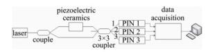
    Figure 1.  Demodulation structure of 3×3 coupler

    由于3×3耦合器受到产品自身工艺加工限制和易受外界的温度、湿度、压力、偏振态等因素影响,输出不能做到功率完全相等和相位差严格满足120°。在3×3耦合器非对称状态下,输出的3路信号y1, y2, y3(本文中均指代信号的电压)可以表示为:

    式中,D1, D2, D3为3路输出的直流分量;E1, E2, E3为3路输出的交流分量;φ1, φ2, φ3为3路输出的相位偏差,具体大小由耦合器和光电探测器的特性决定[17-18]ϕ(t)为外界的扰动信息, t是时间。根据非对称状态的输出形式,需要对原有的3×3耦合器算法进行改进,使其能够对非对称输出进行解调。新型解调算法如图 2所示。

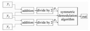
    Figure 2.  Block diagram of the new demodulation scheme

    将非对称状态下输出的其中两路信号y1y2作相加除以2的均值变换,可以得到新的第1路信号p1:

    式中,E4为新的第1路信号的交流分量,φ4为新的第1路信号的相位偏差。在3×3耦合器解调中,直流分量和相位偏差是影响解调质量的最关键参量。同样,新的第3路信号p2

    式中,E5为新的第3路信号的交流分量,φ5为新的第3路信号的相位偏差,新的第2路信号还是原来的第2路信号y2。从新的3路信号可以看出,直流分量的差值经过平均后压缩的非常小,与变换之前的3路信号相比,新的3路信号的直流分量在数值上更加接近;而相位偏差φ1φ2本身也是数值较小,再经过一次压缩后,得到的φ4φ5在数值上就会变得更加小,几乎可以忽略不计[19-20]。所以,光电探测器输出的3路非对称的原始信号经过上述算法后,得到的新的3路信号被矫正至几乎对称的理想状态,再利用传统的对称型解调算法对新的3路信号进行运算,在解调过程中就不会再受到功率不相等和相位偏差的影响,可以更好地得到最终的扰动信号。

2.   仿真与实验结果
  • 利用MATLAB对3路信号进行数值模拟仿真,并且利用输出的任意两路作李萨如图,以便更加直观地反映输出信号之间地幅值和相位差关系。在仿真中,为了模拟输出的非对称状态,取D1=1V,D2=3V,D3=3V,E1=1V,E2=3V,E3=3V,扰动信号ϕ(t)=10×cos(20000πt),图 3为相位偏差为8°的3路李萨如图。

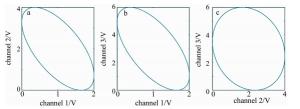
    Figure 3.  Simulated Lissajous signal with a phase deviation of 8°

    从图中可以看出,3路信号此时为非对称状态,第3个李萨如图很明显不是在120°的倾斜角度。所以,不能使用对称解调算法对这3路进行运算。当利用提出的新型解调方案矫正后,如图 4所示。

    Figure 4.  A new demodulation scheme with a phase deviation of 8° simulates three Lissajous signals

    图 4中可以看出,经过提出的新型解调方案矫正后,输出的3路信号近似为对称状态,这样利用对称的解调算法可以进行下一步解调。
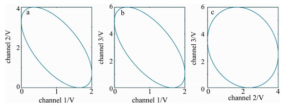
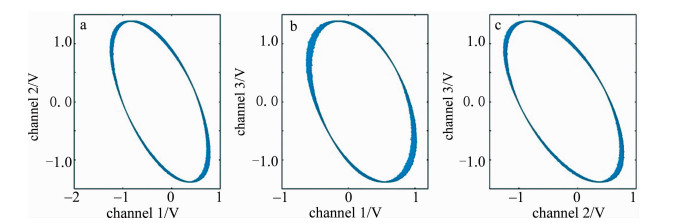
  • 根据图 1图 2中介绍的解调原理,搭建实验平台和编写实验程序。激光器采用RIO公司生产的波长为1550nm窄线宽激光器,输出功率为10mW,线宽为3kHz,该激光器具有输出谱线宽、偏振度低、高功率稳定性、平均波长稳定性好等优点,可以满足传感、测试与影像等研究领域对光源严格的性能要求。实验中利用美国NI公司的USB-6251型数据采集卡,可与LabVIEW兼容,每秒1.25×10⁶个样本的单通道采样率,16路模拟输入通道,PZT产生1V,1000Hz的余弦波作为外界的扰动信号。软件设计中通过LabVIEW对采集到的3路信号进行预处理和解调,再利用MATLAB对结果进行处理和分析。在传统解调方案中得到的3路输出信号的李萨如图为图 5所示。

    Figure 5.  Figures of Lissajous formed by using three signals of traditional demodulation scheme

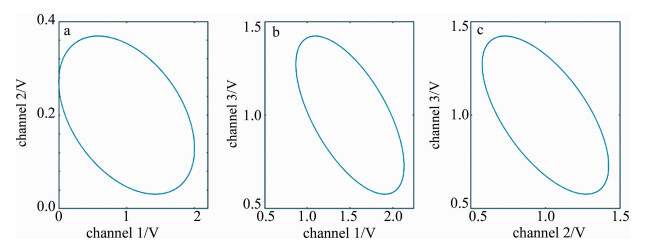
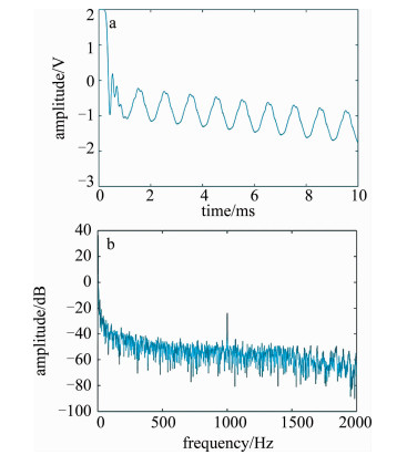
    从3路非对称的输出信号形成的李萨如图形状可以发现,实验中输出的3路信号之间有较大的相位偏差,其中第1个李萨如图已经几乎为正圆。从图 6中看出,利用这3路信号进行解调得到的扰动信号准确度很低,受噪声干扰极大。从频域结果可以估算信噪比约为20dB。在同样的条件,利用提出的新型解调方案得到的实验结果如图 7所示。从图 7中可以发现,采用新型解调方案对原始的信号进行矫正后,得到的新的3路输出信号达到了近似的对称状态,相位差都趋向于120°。利用新的3路输出信号再进行解调则得到了准确度较高的待测信号,从频域结果可以估算信噪比约为65dB,远远高于传统解调方案, 如图 8所示。

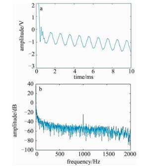
    Figure 6.  The experimental results obtained by using the traditional demodulation scheme

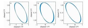
    Figure 7.  Figures of Lissajous formed by using three signals of the new demodulation scheme

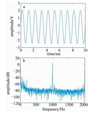
    Figure 8.  Figures of experimental results obtained using the new demodulation scheme

3.   结果分析
  • 从实验结果中可以看出,只有3路信号在在对称的条件下才能取得最好的解调效果。在非对称情况下,3路输入信号之和y为:

    式中,W为增益系数,大小取决于相位偏差。只有在3路输出之和为常数且直流分量相等才能满足对称性输出的条件,使传统的解调算法有效,也就是上式中W=0。如果W=0,则必须满足下列条件:

    从(7)式~(9)式的条件中可以看出,只有当相位偏差都尽可能等于0°时,才能满足对称性条件。假设在非对称条件下,选取下列参量:φ1=φ2=5°,φ3=6°,即3路输出信号有5°左右的相位偏差,可以计算得到E2/E1=0.870, E3/E1=0.855, E3/E2=0.855。当存在相位偏差时,该结果与对称的条件相差过大,同时也不满足传统算法的解调条件,从而无法进行准确解调。所以,在实际解调中,不能忽视该相位偏差,必须尽可能消除相位偏差。而提出的新型算法可以将偏差进行压缩处理,使3路信号接近对称性条件进行输出,从而满足传统算法解调的要求。另外,经过处理的新的3路信号具有直流分量近似相等的特点,也满足对称性的另一个条件。在未来非对称型3×3耦合器的解调研究中,将尝试利用硬件反馈电路和算法结合的方法能更加快速稳定地实现非对称状态的矫正,从而更好地投入实际工程运用。

  • 在解调系统中,噪声主要来自光路和模拟电路部分。由于光路具有抗电磁干扰能力,一般不会受高频噪声干扰,主要由温度漂移等低频干扰,而且包含在相位偏差中,直流漂移噪声一般包含在直流分量中,这些噪声如果不能去除,会使解调结果严重失真。从实验的频域结果中可以发现,提出的解调方案相比传统的解调方法具有更高的信噪比。解调系统中,信噪比可以由S表示:

    式中,I为光功率大小,n1为光噪声大小,n2为电噪声大小。3×3耦合器解调系统中的随机噪声包括随机的直流漂移噪声和相位漂移噪声。对于传统解调方案,假设选取光功率为10mW,总的噪声水平为0.1mW,信噪比约等于20dB;而对于提出的新型解调方案,由于利用均值算法压缩了直流分量和相位偏差,也意味着将包含的随机噪声进行了压缩,减小了噪声水平,有利于提升系统信噪比和稳定性,选取新解调方案中的噪声水平约为10-4mW,信噪比约为50dB。所以,提出的新型的解调方案对于抑制随机噪声和提升信噪比有更好的效果。在今后的研究中,将利用多次均值算法,尝试将噪声进一步压缩,从而得到更高的信噪比和解调准确度,为光纤传感模式识别领域的发展提供参考。

4.   结论
  • 研究了非对称型3×3耦合器解调中,由于耦合器自身工艺制作的限制和外界环境噪声干扰,导致3路信号输出具有功率不相等和相位差不能严格满足120°的非对称状态,从而引起无法准确解调的问题。提出利用均值算法对原始信号进行预处理,压缩了3路输出信号之间功率差与相位的偏差,使经过矫正后新的3路信号近似为对称状态输出。仿真和实验结果表明,提出的新型解调方案可以有效矫正3路输出信号的非对称状态,得到更好的解调效果。该研究成果有益于提高光纤传感的振动模式识别率,并且为光纤传感器领域的科学研究和工程应用提供了很好的参考价值。

Reference (20)

Catalog

    /

    DownLoad:  Full-Size Img  PowerPoint
    Return
    Return