Advanced Search

ISSN1001-3806 CN51-1125/TN Map

Volume 48 Issue 6
Nov.  2024
Article Contents
Turn off MathJax

Citation:

128-channel OPA based on SiN slab waveguide grating antenna

  • Corresponding author: PAN Jiaoqing, jqpan@semi.ac.cn
  • Received Date: 2023-12-31
    Accepted Date: 2024-02-27
  • In order to avoid the saturation phenomenon of output optical power of all silicon optical phased array (OPA) and the low phase shifting efficiency of silicon nitride, a design concept combining silicon and silicon nitride was adopted, which ensured the phase shifting efficiency while achieving high power input. In addition, in order to avoid phase noise caused by mutual coupling between channels, silicon-based integrated OPA had waveguide spacing greater than half wavelength, which led to the presence of gate lobes and limited the scanning range. To solve this problem, a silicon waveguide was used as the input waveguide in front of the antenna to reduce the array elements spacing. The results show that, the chip ultimately achieves a scanning range of 41°×7.4° and a chip loss of 10.7 dB. This study is helpful for further improvement of OPA chips.
  • 加载中
  • [1]

    POULTON C V, BYRD M J, RUSSO P, et al. Long-range LiDAR and free-space data communication with high-performance optical phased arrays[J]. IEEE Journal of Selected Topics in Quantum Electronics, 2019, 25(5): 1-8.
    [2]

    BHARGAVA P, KIM T, POULTON C V, et al. Fully integrated coherent LiDAR in 3D-integrated silicon photonics/65 nm CMOS[C]//2019 Symposium on VLSI Circuits. New York, USA: IEEE Press, 2019: C262-C263.
    [3]

    BABA T, TAMANUKI T, ITO H, et al. Silicon photonics FMCW LiDAR chip with a slow-light grating beam scanner[J]. IEEE Journal of Selected Topics in Quantum Electronics, 2022, 28(5): 1-8.
    [4]

    ABIRI B, FATEMI R, HAJIMIRI A. A 1-D heterodyne lens-free optical phased array camera with reference phase shifting[J]. IEEE Photonics Journal, 2018, 10(5): 1-12.
    [5]

    BYRD M J, POULTON C V, KHANDAKER M, et al. Free-space communication links with transmitting and receiving integrated optical phased arrays[C]//Frontiers in Optics/Laser Science. New York, USA: IEEE Press, 2018: FTu4E. 1.
    [6]

    CLEVENSON H A, SPECTOR S J, BENNEY L, et al. Incoherent light imaging using an optical phased array[J]. Applied Physics Le-tters, 2020, 116(3): 031105. doi: 10.1063/1.5130697
    [7]

    BHANDARI B, WANG ChX, GWON J Y, et al. Integrated optical phased array enabling wavelength-tuned line scanning[C]//2022 27th Opto-Electronics and Communications Conference (OECC) and 2022 International Conference on Photonics in Switching and Computing (PSC). New York, USA: IEEE Press, 2022: 1-3.
    [8]

    KIM J Y, YOON J, KIM J, et al. Demonstration of beam steering using a passive silica optical phased array with wavelength tuning[J]. Optics Letters, 2022, 47(19): 4857-4860. doi: 10.1364/OL.470667
    [9]

    YU L, WANG P, MA P, et al. Two-dimensional beam scanning of passive optical phased array based on silicon nitride delay line[J]. Journal of Lightwave Technology, 2023, 41(9): 2756-2764.
    [10]

    MISUGI Y, OKAYAMA H, KITA T. Demonstration of 2D beam steering using large-scale passive optical phased array enabled by multimode waveguides with reduced phase error[J]. Applied Phy-sics Express, 2022, 15(10): 102002. doi: 10.35848/1882-0786/ac9033
    [11]

    MISUGI Y, OKAYAMA H, KITA T. Compact and low power-consumption solid-state two-dimensional beam scanner integrating a pa-ssive optical phased array and hybrid wavelength-tunable laser diode[J]. Journal of Lightwave Technology, 2023, 41(11): 3505-3512. doi: 10.1109/JLT.2023.3244847
    [12]

    POULTON C V, BYRD M J, RAVAL M, et al. Large-scale silicon nitride nanophotonic phased arrays at infrared and visible wavelengths[J]. Optics Letters, 2017, 42(1): 21-24. doi: 10.1364/OL.42.000021
    [13]

    IM C S, BHANDARI B, LEE K P, et al. Silicon nitride optical phased array based on a grating antenna enabling wavelength-tuned beam steering[J]. Optics Express, 2020, 28(3): 3270-3279. doi: 10.1364/OE.383304
    [14]

    LI Y, CHEN B, NA Q, et al. Wide-steering-angle high-resolution optical phased array[J]. Photonics Research, 2021, 9(12): 2511-2518. doi: 10.1364/PRJ.437846
    [15]

    WANG Q, WANG S, JIA L, et al. Silicon nitride assisted 1×64 optical phased array based on a SOI platform[J]. Optics Express, 2021, 29(7): 10509-10517. doi: 10.1364/OE.420921
    [16]

    LUO G, YU L, MA P, et al. A large-scale passive optical phase array with 1024 channels[J]. IEEE Photonics Technology Letters, 2023, 35(17): 927-930. doi: 10.1109/LPT.2023.3289231
    [17]

    WANG P F, LUO G Zh, XU H Y, et al. Design and fabrication of a SiN-Si dual-layer optical phased array chip[J]. Photonics Research, 2020, 8(6): 06000912.
    [18]

    LUO G, WANG P, MA J, et al. Demonstration of 128-channel optical phased array with large scanning range[J]. IEEE Photonics Journal, 2021, 13(3): 1-10.
    [19]

    LIU Y, HU H. Silicon optical phased array with a 180-degree field of view for 2D optical beam steering[J]. Optica, 2022, 9(8): 903-907. doi: 10.1364/OPTICA.458642
    [20]

    TYLER N A, FOWLER D, MALHOUITRE S, et al. SiN integrated optical phased arrays for two-dimensional beam steering at a single near-infrared wavelength[J]. Optics Express, 2019, 27(4): 5851-5858. doi: 10.1364/OE.27.005851
    [21]

    CHUL S M, MOHANTY A, WATSON K, et al. Chip-scale blue light phased array[J]. Optics Letters, 2020, 45(7): 1934-1937. doi: 10.1364/OL.385201
    [22]

    HSU C P, LI B, SOLANO-RIVAS B, et al. A review and perspective on optical phased array for automotive LiDAR[J]. IEEE Journal of Selected Topics in Quantum Electronics, 2021, 27(1): 1-16.
    [23]

    SHANG K, QIN C, ZHANG Y, et al. Uniform emission, constant wavevector silicon grating surface emitter for beam steering with ultra-sharp instantaneous field-of-view[J]. Optics Express, 2017, 25(17): 19655. doi: 10.1364/OE.25.019655
    [24]

    RAVAL M, POULTON C V, WATTS M R. Unidirectional waveguide grating antennas with uniform emission for optical phased arrays[J]. Optics Letters, 2017, 42(13): 2563-2566. doi: 10.1364/OL.42.002563
    [25]

    YU L, MA P, LUO G, et al. Adoption of large aperture chirped grating antennas in optical phase array for long distance ranging[J]. Optics Express, 2022, 30(15): 28112-28120. doi: 10.1364/OE.464358
    [26]

    ZHANG L, WANG Y, HOU Y, et al. Uniform rectangular distribution of far-field intensity by optical phased array[J]. Optics Communications, 2022, 507: 127661. doi: 10.1016/j.optcom.2021.127661
    [27]

    KOMLJENOVIC T, HELKEY R, COLDREN L, et al. Sparse aperiodic arrays for optical beam forming and LiDAR[J]. Optics Express, 2017, 25(3): 2511-2528. doi: 10.1364/OE.25.002511
    [28]

    FATEMI R, KHACHATURIAN A, HAJIMIRI A. A nonuniform sparse 2-D large-FOV optical phased array with a low-power PWM drive[J]. IEEE Journal of Solid-State Circuits, 2019, 54(5): 1200-1215. doi: 10.1109/JSSC.2019.2896767
    [29]

    POLKOO S S, RENSHAW C K. Hybrid imaging-based beam steering system using a sparse photonic integrated circuit outcoupling array[C]//Conference on Lasers and Electro-Optics. New York, USA: IEEE Press, 2020: JTh2B. 25.
    [30]

    POULTON C V, BYRD M J, RUSSO P, et al. Coherent LiDAR with an 8, 192-element optical phased array and driving laser[J]. IEEE Journal of Selected Topics in Quantum Electronics, 2022, 28(5): 6100508.
    [31]

    SAYYAH K, SARKISSIAN R, PATTERSON P, et al. Fully integrated FMCW LiDAR optical engine on a single silicon chip[J]. Journal of Lightwave Technology, 2022, 40(9): 2763-2772. doi: 10.1109/JLT.2022.3145711
    [32]

    WANG P F, LUO G Z, YU H Y, et al. Improving the performance of optical antenna for optical phased arrays through high-contrast grating structure on SOI substrate[J]. Optics Express, 2019, 27(3): 2703-2712. doi: 10.1364/OE.27.002703
    [33]

    HAN K, YURLOV V, YU N E. Highly directional waveguide grating antenna for optical phased array[J]. Current Applied Physics, 2018, 18(7): 824-828. doi: 10.1016/j.cap.2018.04.004
    [34] 郑伟, 王超, 杨文丽, 等. 基于色散光学的光波束形成网络[J]. 激光技术, 2022, 46(2): 188-192. doi: 10.7510/jgjs.issn.1001-3806.2022.02.007

    ZHENG W, WANG Ch, YANG W L, et al. An optical beamforming network based on dispersing optics[J]. Laser Technology, 2022, 46(2): 188-192(in Chinese). doi: 10.7510/jgjs.issn.1001-3806.2022.02.007
  • 加载中
通讯作者: 陈斌, bchen63@163.com
  • 1. 

    沈阳化工大学材料科学与工程学院 沈阳 110142

  1. 本站搜索
  2. 百度学术搜索
  3. 万方数据库搜索
  4. CNKI搜索

Figures(10)

Article views(490) PDF downloads(4) Cited by()

Proportional views

128-channel OPA based on SiN slab waveguide grating antenna

    Corresponding author: PAN Jiaoqing, jqpan@semi.ac.cn
  • 1. Key Laboratory of Optoelectronic Materials and Devices, Institute of Semiconductors, Chinese Academy of Sciences, Beijing 100083, China
  • 2. College of Materials Science and Opto-electronic Technology, University of Chinese Academy of Sciences, Beijing 100049, China

Abstract: In order to avoid the saturation phenomenon of output optical power of all silicon optical phased array (OPA) and the low phase shifting efficiency of silicon nitride, a design concept combining silicon and silicon nitride was adopted, which ensured the phase shifting efficiency while achieving high power input. In addition, in order to avoid phase noise caused by mutual coupling between channels, silicon-based integrated OPA had waveguide spacing greater than half wavelength, which led to the presence of gate lobes and limited the scanning range. To solve this problem, a silicon waveguide was used as the input waveguide in front of the antenna to reduce the array elements spacing. The results show that, the chip ultimately achieves a scanning range of 41°×7.4° and a chip loss of 10.7 dB. This study is helpful for further improvement of OPA chips.

0.   引言
  • 随着无人驾驶、智能机器人等领域的迅速发展,以激光雷达(light detection and ranging, LiDAR)为代表的环境感知技术逐渐发展。目前商业化的激光雷达主要采用机械结构作为旋转部件或者探测单元选取部件,使得雷达整体的寿命并不能完全满足实际应用需求[1-3]。为此,研究者们提出了全固态架构的光学相控阵(optical phased array, OPA),其具有功耗小、成本低、分辨率高以及转向速度快等优势[4-11]。目前各种架构形式的OPA已经有报道。根据扰动光栅的结构主要可以分为微扰型[12-16]以及平板波导光栅型[17-19]等。根据扰动强度随着天线的分布可以分为常规均匀结构[20-22]和啁啾光栅结构[23-26]。根据OPA通道间距可以分为等间隔分布阵列以及稀疏阵列[27-29]

    在OPA实际应用探索中,美国麻省理工学院的团队当前较为领先。2020年,该团队通过将SiN引入OPA,实现了更大的饱和功率输出。2022年,报道了最大规模为8192个通道的OPA,且基于调频连续波技术(frequency-modulated continuous wave, FMCW)实现了35 m距离内反射率为10%的目标检测[30]。在这项研究中,光束出射功率为50 mW。根据激光雷达方程,无人驾驶环境中所需的200 m最大探测范围需要出射功率达到1.6 W[31]。由于Si的非线性效应以硅波导损伤阈值的限制,目前常见的OPA无法实现上述高功率输出。

    OPA面临的另一个挑战是为了避免通道间串扰引起相位噪声,波导间距一般大于OPA工作波长(1500 nm~1600 nm),这使得探测光束干涉之后将在相位方向(φ)出现多个栅瓣,进而导致OPA的扫描范围严重受限。该问题的解决方案主要是采用稀疏阵列设计和平板波导光栅设计。在实际制造中,考虑到由于稀疏阵列的天线间距非固定值所引起通道间的相位噪声将使得远场光斑质量较差。相比之下,平板波导光栅设计则没有相位噪声,同时其所能够实现的转向角也远大于稀疏阵列。因而,平板波导光栅设计被认为是一种更好的选择。此外,在波长方向(θ)一半通过模式复用以及视场拼接实现扫描范围的增大。

    本文作者基于Si-SiN-SiN平台的128个通道平板波导光栅OPA,使用SiN作为总线波导、分光阵列和平板波导光栅天线,使用Si作为热光移相器,在1500 nm~1600 nm波长调谐范围内,该OPA实现了41°×7.4°(φ×θ)的扫描范围,展现出极大的应用潜力。

1.   设计与制造
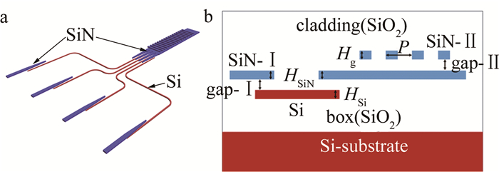
  • 本文作者所设计的OPA如图 1所示,红色为Si,蓝色为SiN。制造材料包括自上而下分布的两层间距150 nm的SiN以及一层Si,其中,SiN-Ⅰ层被用来制作总线波导、分光阵列和平板波导;SiN-Ⅱ层被用来制作扰动光栅;而Si层则被用来制作热光移相器;各层之间的间隔层、掩埋层以及盖层为氧化硅。此次制作的具体参数如下:SiN波导厚度HSiN=200 nm,宽度为1.5 μm;SiN光栅厚度Hg=200 nm,光栅周期P=900 nm,占空比为50%;而Si波导厚度HSi=220 nm,宽度为450 nm,相邻波导间隔为2 μm。此外,SiN-Ⅰ层与Si层之间的光互连是通过模斑转换器实现的。

    Figure 1.  a—schematic of the OPA b—side view

    该OPA通过移相器阵列对各通道进行相位调谐实现光在φ轴的光束偏转及对输入光进行波长调谐,实现光束在θ轴的光束偏转。其光束转向公式为[32]

    式中:λ为输入光波长;d为Si波导相邻间隔,即2 μm;Δϕ为相邻通道间的相位差;neff为天线的光栅有效折射率;nc为包层折射率。Δϕ=±π时,主瓣与第一栅瓣强度相等,此时主瓣的转向角度即为光斑最大转向角度。之后可以得到光斑发散角为[33]

    式中:L为天线长度,L=mPm为光栅周期数;N为输入通道数。

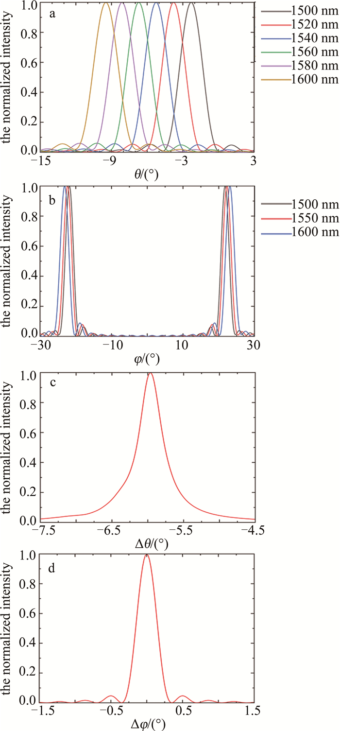
    首先使用时域有限差分法(finite-difference time-domain, FDTD)对天线性能进行评估。在天线视场计算中,为了节省资源以及减小仿真时间,将模型缩小为16通道。如图 2a图 2b所示,当输入光从1500 nm调谐至到1600 nm时,所设计的OPA在θ方向上的扫描范围为7.3°,在φ方向上的扫描范围随着波长增大从43.5°逐渐增大到46.2°。在发散角仿真计算时,将模型扩展到了128输入通道和300 μm的天线长度。由图 2c图 2d可得,输入光波长为1550 nm时的发散角为0.3° ×0.4°(Δφ×Δθ)。根据式(2),可以得到天线有效长度L=200 μm,阵列宽度Nd=256 μm。

    Figure 2.  a—beam steering range in θ axis b—beam steering range in φ axis c—divergence angle in θ axis d—divergence angle in φ axis

    本文中所展示的OPA由新加坡Advanced Micro Foundry代工,图 3a为设计的版图,图 3b为封装后的芯片。

    Figure 3.  a—design layout b—packaged chip

2.   表征结果
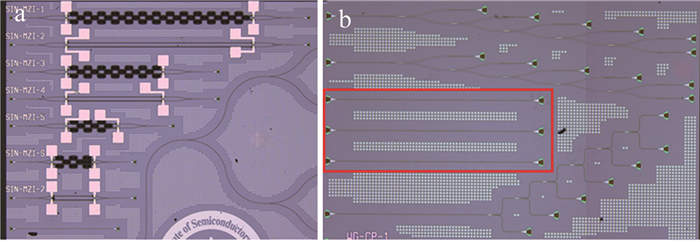
  • 图 4a为热光移相器件测试结构。编号为SIN-MZI-2的测试结构用于测试芯片中使用的热光移相器的效率。图 4b为位于中间的第2组5级级联1×2多模干涉耦合器结构,用于测试光学相控阵中使用的1×2多模干涉耦合器损耗。红框中的3组波导结构用于测试Si波导和SiN波导的模斑转换器,其自上而下分别有0对、1对和3对Si-SiN-Si模斑转换器过渡。OPA中使用的热光移相器电阻为11 kΩ,测试得到的2π相移电压约为18 V,对应的电功耗为30 mW。由此得到该128通道光学相控阵的驱动电路需要保证每一个通道都要能够提供至少18 V的电压和30 mW的电功率。SiN的热光系数约为Si的1/5,如果使用SiN热光移相器,所需要的电功率将超过100 mW。

    Figure 4.  a—test structure of thermo-optic phase shifter b—test structure of 1×2 multimode interferometric coupler

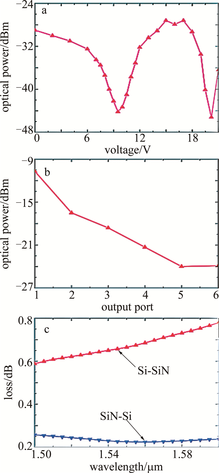
    图 5a为基于Si热光移相器的马赫-曾德尔调制器特性。图 5b为从第1级~第5级多模干涉耦合器的各个输出端口得到的光功率。去掉端口2的大偏差数据点后,对端口1~端口5得到的光功率做线性拟合得到直线斜率为-3.34,即1级多模干涉耦合器的单端口插损为3.34 dB。最后1级多模干涉耦合器的输出端口功率分别为-24 dBm和-23.9 dBm,得到其分光比为49.4%∶50.6%。图 5c表示了相同输入功率下,Si-SiN模斑转换器的耦合损耗。

    Figure 5.  a—characterization of Mach-Zehnder modulator based on the silicon thermo-optic phase shifter b—output power at each port of the cascaded silicon nitride multimode interferometric coupler c—losses of silicon and silicon nitride waveguide spot size converters

    一对模斑转换器完成一次Si-SiN-Si的光功率转移,其耦合损耗L计算方式为:

    式中:L0L1L3分别为图 4b红框中3个Si-SiN模斑转换器测试结构的损耗;L0为自上而下第1个结构(包含0对模斑转换器)的损耗;L1为第2个结构(包含1对模斑转换器)的损耗;L3为第3个结构(包含3对模斑转换器)的损耗。通过式(3)等效取多次平均,降低随机误差的影响。由此得到,在1550 nm时,一对模斑转换器的耦合损耗为0.52 dB。

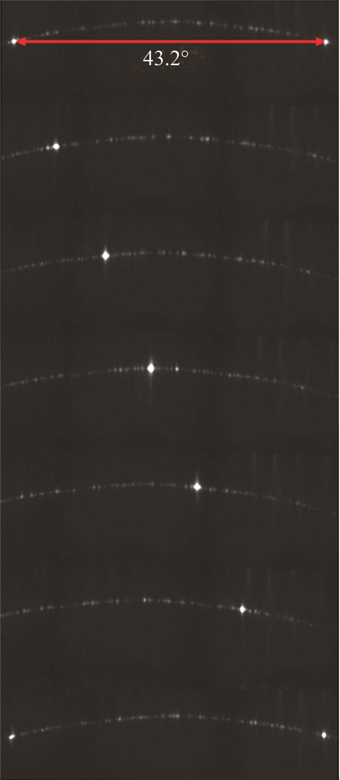
    图 6为输入光波长1550 nm时,芯片在φ方向上的转向结果。对应扫描范围为43.2°,与仿真结果一致。此外,从图中可以看出,转向中远场存在大量杂散光,测试结果表明所设计的芯片旁瓣电平抑制比(side-lobe level, SLL)仅为8 dB,小于理论的12 dB左右。这是由于此次设计的芯片电极较为密集,封装技术难度大,最终128个热光移相器中大约100个正常工作,故障率约为21%。图中的杂散光就是由上述故障的通道所导致的。在接下来的工作中,将优化设计以消除负面结果。

    Figure 6.  Beam steering in φ axis (λ=1550 nm)

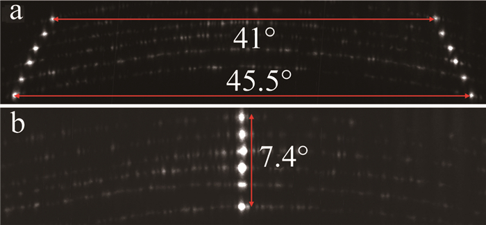
    图 7为输入光波长从1500 nm调谐至1600 nm时的扫描结果。从图中可以看出,θ方向上的扫描范围为7.4°。同时,φ方向上的扫描范围随着波长的增加逐渐从41°增加到45.5°。

    Figure 7.  a—beam steering angle in φ axis (λ=1500 nm~1600 nm) b—beam steering angle in θ axis (λ=1500 nm~1600 nm)

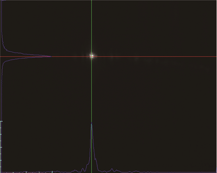
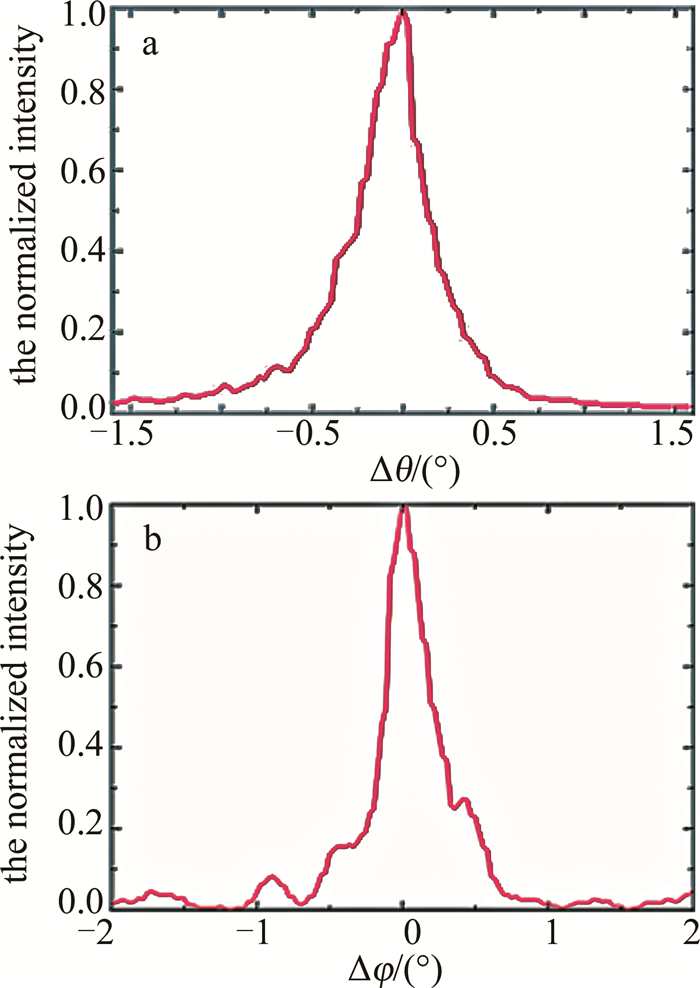
    图 8为输入光波长为1550 nm时的光斑。图 9则显示了当输入光波长为1550 nm时θ轴和φ轴的发散角,对应值为0.33°×0.37°(Δφ×Δθ)。

    Figure 8.  Spot at input light wavelength of 1550 nm

    Figure 9.  a—divergence angle in θ axis b—divergence angle in φ axis

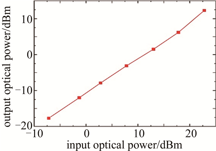
    图 10中为芯片输出光功率和输入光功率的关系。对数据进行拟合可以得到芯片的整体损耗为10.8 dB。其中SiN波导的损耗为1.2 dB/cm,SiN的端面耦合器损耗为3.6 dB,7级光分束阵列的损耗为2.38 dB,SiN-Si-SiN的波导过渡结构损耗为0.52 dB,从而得到天线的损耗约为3 dB。同时随着输入光功率增加,未出现输出光功率趋于饱和的现象,很好地满足了高功率输入的需求,达到设计预期。

    Figure 10.  Chip output & input optical power

3.   结论
  • 本文中基于Si-SiN体系的128个通道平板波导光栅OPA芯片,通过使用平板波导光栅设计,成功实现了φ方向扫描范围增大。测试结果表明,所设计的芯片视场角为41°×7.3°(φ×θ),发散角为0.33°×0.37°(Δφ×Δθ)。受限于移相器控制通道21%的故障率,SLL仅为8 dB。此外,SiN的引入也成功实现了高功率输入的目标。在接下来的工作中,将会通过增大天线口径来降低发散角,改善设计和封装工艺以实现SLL的提高,探索基于色散光学的光真延时线代替光学移相器的可行性[34]。总体而言,本文中所设计的OPA展示出在提高输出功率以及增大扫描范围等方面的优势。

Reference (34)

Catalog

    /

    DownLoad:  Full-Size Img  PowerPoint
    Return
    Return