 Map
Map


HTML
-
热成形钢是一种超高强度钢(抗拉强度大于780 MPa),根据成分种类不同,其淬火后抗拉强度可达1000 MPa~2000 MPa[1]。热成形钢主要用作汽车白车身零件,由于其强度高,在减少钢板厚度的同时能保证安全性能,达到节约能源和汽车轻量化的目的[2]。研究表明,汽车重量减少10%,油车可降低6%~8%的油耗,电车可提升13.5%的续航[3]。汽车轻量化成为节能减排和降本增效的有力途径,热成形钢在白车身中应用占比逐年提高[4]。
热成形技术具有零件淬火后强度高、高温成形回弹小、成形精度高、成形载荷小、一次成形等优点[5]。然而热成形零件的抗拉强度越高,其硬度越高,塑性、韧性越低,其焊接性能越差,热影响区应力大,焊点表现脆性,受到冲击时易开裂[6-7]。热成形钢铆接时, 由于铆钉脚受到应力过大,发生变形,导致综合性能不佳[8-9]。在零件连接位置进行局部加热回火,可以消除内应力,降低硬度,提高其塑性[10]。一般采用局部感应加热、电极加热等方法进行回火,但这些方法存在灵活性差、批量生产需要额外工装、控温精度差等问题[11]。
激光软化技术将激光作为热源,对选定区域进行局部加热,降低局部区域的硬度,提高塑性,消除内应力[12-13]。激光软化技术可控性和灵活性好,通过调节激光能量功率、扫描速率、光斑大小等参量,实现不同的软化性能,结合数控机器人可以实现不同部位和软区形状大小的定制化需求[14-15]。本文中通过激光对热成形钢进行局部软化,研究激光软化工艺和软区组织的性能变化。
-
本文中所采用的原材料为退火态CR950/1300HS+AS,厚度1.8 mm,其化学成分如表 1所示。先将原材料钢板在950 ℃保温5 min完全奥氏体化,然后平板模水冷淬火并保压10 s,得到超高强钢板坯料待用。
C Si Mn P S Al B N Cr Ti Mo 0.00182 0.00862 0.0111 0.00006 ≤0.000001 0.0174 0.000026 0.000092 0.00191 0.000303 0.000049 Table 1. Chemical composition of CR950/1300HS steel (mass fraction)
激光软化设备采用TruDisk4002,波长1030 nm,发射高斯光束垂直照射钢板表面,在待软化区域按照设定路径快速移动,加热温度设定为800 ℃,实现快速高温回火效果。本文中设计软区大小为20 mm×20 mm。
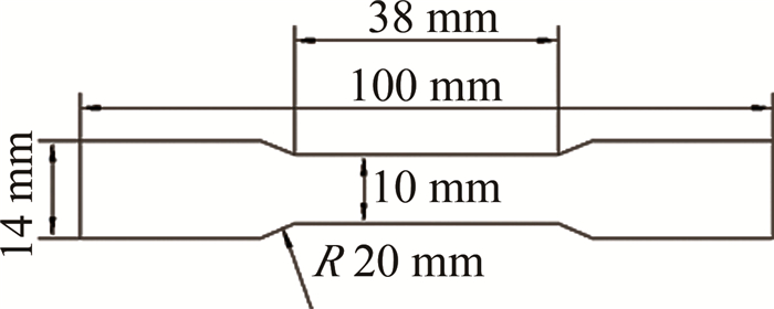
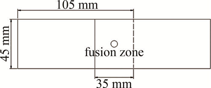
本文中采用SCV-50A维氏硬度计,每隔2 mm测量试样的显微硬度,压头载荷为9.8 kg,保压时间为10 s。采用电子式万能试验机Instron 3382,拉伸速率为2 mm/min,拉伸试样尺寸如图 1所示。点焊拉伸剪切试验的试样尺寸如图 2所示。软化试样经过镶嵌、打磨、抛光后,用体积分数为4%硝酸酒精溶液腐蚀,采用DS-300金相显微镜来观察试样金相组织。
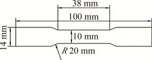
Figure 1. Tensile specimen size
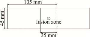
Figure 2. Size of tensile shear specimens for spot welding
-
淬火后的原材料的金相组织如图 3所示。由于该材料中含有更多的B元素,会使得钢的淬透性提高,从而淬火后更容易获得更多的马氏体,可以看出基体组织为板条状马氏体,组织内有许多相互平行的板条束组成的马氏体块,各马氏体块之间以大角度界面分开,所以金相中各马氏体块出现黑白交替的色调。在母材表层有一厚度为35 μm~40 μm的铝硅镀层,图中镀层主要由厚度约28 μm~30 μm的Al-Si合金层和厚度约10 μm的Fe2SiAl7金属间化合层组成。由于镀层的保护作用,钢板在热成形的过程未出现氧化脱碳,基体为全马氏体组织。
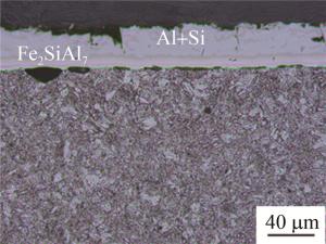
Figure 3. Metallographic structure of base metal
热影响区和软区位置横截面的金相组织如图 4所示。随着加热温度的升高,热影响区金相主要有图 4a、图 4b、图 4c 3种,软区(中心加热区)金相为图 4d。图 4a中组织为回火马氏体,该温度状态主要处于回火第一和第二阶段,马氏体开始分解,析出ε/η过渡碳化物,其中ε相成分介于Fe2C和Fe3C之间,η相成分为Fe2C,此时分辨马氏体板条束的形状和大小,但条束边界和马氏体块角度的形态开始模糊。图 4b中组织为回火马氏体和渗碳体,该温度状态主要处于回火第三阶段,马氏体继续分解,板条束的界面消除,马氏体束取向还能分辨,析出的过渡碳化物在大角度界面处转变为渗碳体并钉扎住界面,使得板条马氏体的形态能稳定存在至很高的回火温度。图 4c中组织为铁素体和渗碳体,该温度状态主要处于回火第四阶段,由于回火时间较短,大部分铁素体仍保持条束状的外形,此时渗碳体发生粗化并逐渐球化,分布在铁素体基体中,渗碳体粗化后不能有效钉扎大角度界面,表现为界面数量减少,降低界面能,晶粒长大并形成等轴铁素体。图 4d中组织为回火索氏体,使得该区域具有较低的硬度,塑性和韧性提高[16]。回火索氏体为待软化区经过激光快速升温至800 ℃,随后空冷得到。此时的回火阶段中马氏体条束的痕迹已经消失,渗碳体数量增加且球化比较完全,表现为铁素体基体中弥散分布着大量的细粒状渗碳体,由于渗碳体弥散程度较高,金相中无法区分晶界[17-18]。
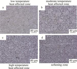
Figure 4. Metallographic microstructure of heat-affected zone and softening zone
-
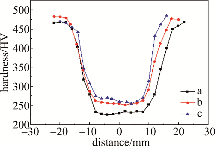
测试试样软区横截面厚度中心硬度,不同位置的硬度变化曲线如图 5所示。表 2为图 5中不同工艺下的实验数据。可以看出,在800 ℃下,激光扫描速率越慢,软区硬度越低,软区硬度曲线越平稳,这是因为扫描速率越慢,在加热区域内的保温时间就越长,组织扩散越充分,实际回火效果越好,得到的回火索氏体越多,其弥散性越好。热影响区随着距离中心越远,硬度越高,直至达到母材硬度范围,这与金相的结果一致,表明热影响距离越远,该区域的温度越低,该区域所处的回火阶段越低,所得到的组织硬度逐渐升高。实验中在不同的激光扫描速率下,扫描区域为20 mm×20 mm,实际软区宽度均为16 mm左右,说明在激光加热温度不变的情况下,改变激光扫描速率,主要影响了软区的硬度,实际软区宽度(16 mm)和热影响区宽度(10 mm)变化不大。
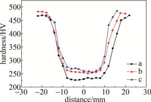
Figure 5. Hardness of softening zone under different processes
process temperature/℃ scanning direction linear speed/(mm·s-1) scan time/s average hardness of soft zone/HV a 800 2 10 230 b 800 4 5 256 c 800 10 2 265 Table 2. Laser softening process data
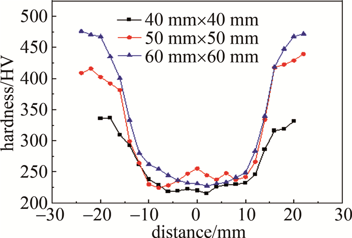
通过对不同尺寸大小试样的中心区域进行软化,扫描区域为20 mm×20 mm,激光工艺为800 ℃,扫描方向线速率为2 mm/s,研究非加热区域大小在软化过程中受热影响所产生的变化,测量的硬度结果如图 6所示。试样尺寸越小,软区位置最低硬度会稍微降低,硬度曲线也越平稳,这是因为小的试样尺寸冷速会较慢,相当于其回火时间越长,软区的回火后硬度会更低,组织均匀性更好。随着试样尺寸的增大,非加热区参与对软区的传热和散热体积增加,导致非加热区在受热影响后在相同的距离时材料温度相比越低,其回火阶段越低,在相同的距离有更高的硬度。试样尺寸小于60 mm×60 mm时,试样散热能力不足,整个试样软区四周均会受热影响区而硬度降低。
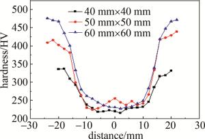
Figure 6. Softening zone hardness of different sizes samples
-
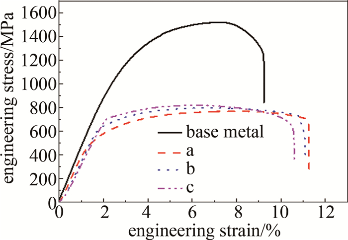
热成形钢母材和激光软化试样的拉伸工程应力应变曲线如图 7所示。拉伸性能数据如表 3所示。软化试样a、b、c(分别对应3种不同工艺)的塑性变形均发生在软化范围内,所以软化试样计算断后伸长率的原始标距采用软区宽度20 mm,这样能更真实地反映软区内的断后伸长率。母材是全马氏体组织,具有较高抗拉强度和屈服强度,但其塑性较低。由软化工艺得到的软区组织主要为回火索氏体,其抗拉强度降低至母材的50.53%~53.82%,但塑性会大幅提升,而断后伸长率为母材的172.26%~188.08%。
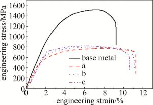
Figure 7. Tensile curves of different softening processes
sample tensile strength/MPa yield strength/MPa elongation after fracture/% reduction of section/% base metal 1518 1155 9.23 23.15 a 767 488 17.36 36.16 b 798 655 16.65 34.77 c 817 723 15.90 37.74 Table 3. Tensile test data
随着扫描方向线速率的增加,软化试样抗拉强度稍微提高,与硬度提高趋势一致;激光扫描速率增加对软化试样屈服强度的影响较明显,其屈服强度提高较多,这是由于激光扫描速率加快,回火时间会缩短,回火组织扩散时间缩短,仍存在较多位错,而且渗碳体球化和弥散程度降低,还能起到钉扎作用,所以屈服强度提高;软区断后伸长率稍微下降。
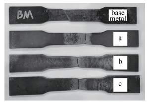
母材和软化试样拉伸后的外观如图 8所示。断裂方式均为韧性断裂。母材断面类型为剪切滑移型断面,断裂面与拉伸方向成45°角,有一定的滑移现象,剪切唇占断面面积的2/3。软化试样断面类型为杯锥状断面,变形区域集中在软区内,随着应力的增大, 在软区中间出现明显颈缩现象,断面收缩率相比母材增加,由于试样较薄(厚度1.8 mm),断面只有剪切唇区[19]。

Figure 8. Appearance of tensile specimen after fracture
-
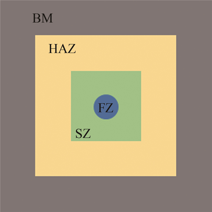
将两片软化试样进行搭接,制作电阻点焊拉伸剪切试样,图 9为激光软区范围和焊点位置示意图。从外向内分别为母材(base metal,BM);热影响区(heat-affected zone,HAZ);软区(softening zone,SZ);焊核区(fusion zone,FZ)。电阻点焊参数为焊点直径6.7 mm、电流8.6 kA、压力4.2 kN、焊接时间400 ms、冷却时间30 ms。
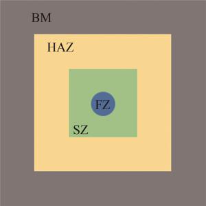
Figure 9. Diagram of softening zone range and welding spot position
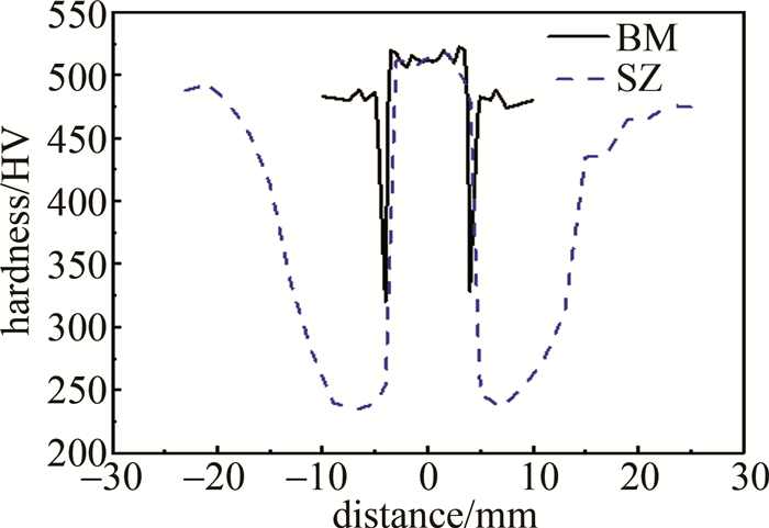
测量比较母材焊接试样、软化焊接的焊点硬度,结果如图 10所示。母材CR950/1300HS+AS正常点焊时,焊核区域硬度515 HV左右,热影响区硬度会在1 mm~2 mm内快速降低又快速升高,最低硬度320 HV。预先软化后,在软区内点焊,焊核区域硬度515 HV左右,之后受焊接热影响硬度在1 mm范围快速降低至软区硬度,再向外经过软区,然后硬度在10 mm宽度的过渡区内逐渐上升至母材硬度。通过焊接前激光软化,相比传统焊接后回火工艺,可以实现不降低焊点硬度,调节热影响区最低硬度,使热影响区宽度增加,硬度变化趋势减缓,改善热影响区的应力集中现象。
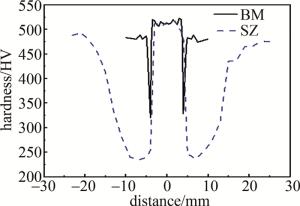
Figure 10. Hardness diagram of welding spot in SZ
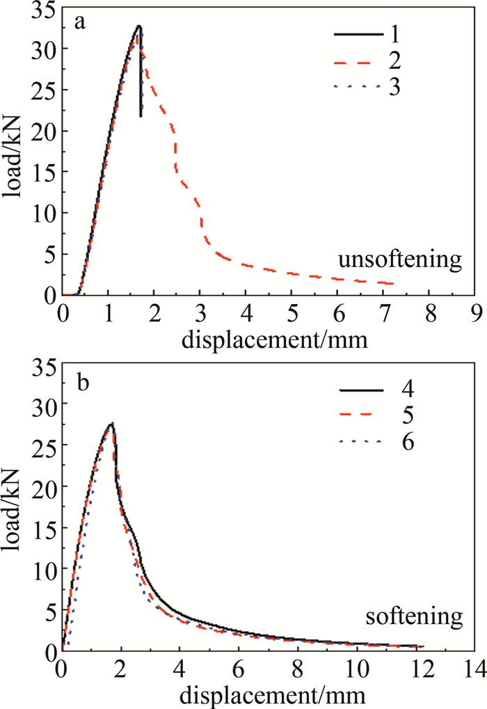
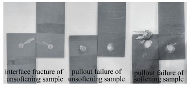
比较未软化的母材点焊拉伸剪切实验、软化试样的点焊拉伸剪切实验,结果如表 4所示。实验的位移载荷图如图 11所示。软化后试样的最大试验力相比未软化的降低,但软化后不同试样的焊点拉伸剪切曲线会更一致,且不会出现界面断裂的现象,其最大断裂位移增加60%。软化前最大吸收能量为61.92 J(见曲线2),软化后最大吸收能量为68.20 J(见曲线4),提升了10.14%。试样断裂后外观如图 12所示。可以看到,未软化的母材试样,焊接接头断裂方式包含界面断裂和熔核拔出,其中界面断裂表明裂纹在结合面扩张速度极快,接头在达到最大试验力后瞬间失效,焊点沿着两片试片结合面断裂成两半,断裂面较平整,实际应用中应该避免出现界面断裂;熔核拔出则是在达到最大试验力后,裂纹在圆形熔核最上端产生,随着拉伸进行裂纹沿着熔核圆弧向两边扩展,熔核作为一个整体逐渐从试片中拔出,直径约7.5 mm,试片中留下圆形空缺,搭接端出现变形,熔核拔出失效模式裂纹扩展缓慢,在裂纹扩展阶段焊点和基体仍保持机械连接,能通过变形的方式吸收后续载荷[20]。软化试样的焊接接头断裂方式均为熔核拔出,和母材试样不同的是其熔核会连带着部分软区一同拔出,拔出范围更大,呈椭圆形,长轴约13.5 mm。
technology thickness combination/mm number maximum test force/N unsoftening 1.8+1.8 1
2
332717
31757
32206softening 1.8+1.8 4
5
627070
27436
27645Table 4. Properties of welding spot tensile and shear
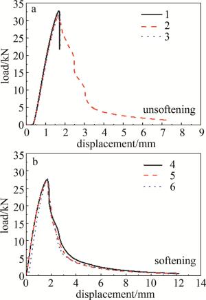
Figure 11. Displacement loading diagram
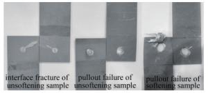
Figure 12. Appearance of welding spot tensile shear specimen after fracture
2.1. 金相组织


2.2. 软区硬度
2.3. 拉伸结果
2.4. 软区内点焊性能研究
-
(a) 通过激光加热回火,成功实现了热成形钢局部区域的定制软化。一定情况下,激光扫描速度越慢,软区硬度越低。温度为800 ℃、扫描线速率为2 mm/s时,软区组织为回火索氏体,软区硬度为230 HV,抗拉强度767 MPa,屈服强度488 MPa,断后伸长率17.36%,软化后为韧性断裂。
(b) 热成型钢激光软化后进行点焊,焊核硬度(515 HV)不变,激光软化可以调节热影响区最低硬度,增加热影响区宽度,使硬度变化趋势减缓,改善热影响区的应力集中现象。软化后试样的焊点拉伸剪切最大试验力相比未软化的降低,但软化后试样的焊点拉伸剪切曲线会更一致,且不会出现界面断裂的现象,均为熔核拔出,其最大断裂位移增加60%,最大能量吸收功提升了10.14%。
 DownLoad: