 Map
Map


HTML
-
随着成形砂轮大量应用在高精度脆硬材料零件加工中,比如半导体、陶瓷、复合材料等材料的加工,砂轮轮廓精度的要求日益严格。通过检测成形砂轮轮廓,能够获取成形砂轮的轮廓尺寸,检查其精度是否满足要求; 同时为实际磨削加工中,工件型面的误差分析和补偿提供依据[1]; 另外还可以了解砂轮的轮廓磨损情况,定位轮廓发生磨损的位置,确定轮廓待修整余量,指导砂轮修整[2]。作为成形砂轮生产和修整环节中的一项关键技术,研究成形砂轮轮廓检测方法有重要作用和意义。
目前常用的砂轮轮廓检测方法有磨削复映检测法、接触式检测法、传统光学投影检测法和单截面视觉检测法等[3]。PENG等人[4-5]设计了一套激光整形测控系统,结合磨削复映和机器视觉技术检测砂轮的轮廓,并根据检测结果对砂轮补偿整形。LEI等人[6]搭建了一套砂轮轮廓视觉检测系统,实现轮廓尺寸的在机检测,同时分析修整偏差并改善修整工艺以提高修整质量。NIU等人[7-8]设计了轮廓在线检测系统实时采集被磨削工件的图像,提取并测量实际轮廓,同时与理论轮廓对比,判断砂轮磨损状态和计算磨损量。MU等人[9-10]使用基恩士LK-G30激光位移传感器搭建一套实验检测系统,可以非接触地检测砂轮的磨损量,整周期测量时,其线性度小于0.6%。ZHOU等人[11]使用基恩士LK-H020激光位移传感器螺旋扫描砂轮的外轮廓获取轮廓数据并进行滤波和插值得到圆弧轮廓的点云数据,实现凸圆弧金刚石砂轮的轮廓检测和评价。SHI等人[12]使用2维激光位移传感器采集砂轮轮廓数据,建立点云模型,获取砂轮廓形的圆弧半径和圆度误差,正确反映成形砂轮的磨削工件的精度。SHAO等人[13]搭建了一种砂轮形貌采集系统,提取高精度的磨损平面,评价砂轮的磨损状态和磨削性能。XU等人[14-16]在曲线磨床上设计了在位测量系统,通过电荷耦合器件(charge-coupled device,CCD)相机采集轮廓图像,使用轮廓拟合测量出轮廓尺寸数据,测量结果与磨削复映法结果接近。LI等人[17-18]搭建了砂轮轮廓测量系统,进一步研究了自动对焦和图像拼接等算法,并通过检测圆柱形和半球形轮廓的砂轮进行验证,可实现砂轮轮廓的高效测量以及轮廓参数的评价。
现有的检测方法只能满足精度和效率中的单方面需求,并主要针对于凸圆弧砂轮,对于其它轮廓的成形砂轮检测研究相对较少,且只测量某一截面轮廓,无法反映砂轮的全局轮廓信息。
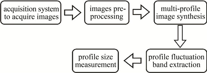
为同时满足成形砂轮激光修整过程中高效、高精度的检测需求,本文作者对成形砂轮轮廓的检测技术开展研究。搭建基于砂轮激光修整机床的图像采集系统对砂轮轮廓进行旋转采样,获取砂轮圆周方向的全局轮廓图像;提出一种多轮廓图像合成检测方法,有效利用砂轮全圆周的轮廓信息, 进一步提出轮廓波动带概念,通过轮廓波动带对砂轮进行轮廓尺寸检测。为了验证该方法的检测效果,将该本文中的检测方法与磨削复印检测法和单截面视觉检测法进行了对比分析。
-
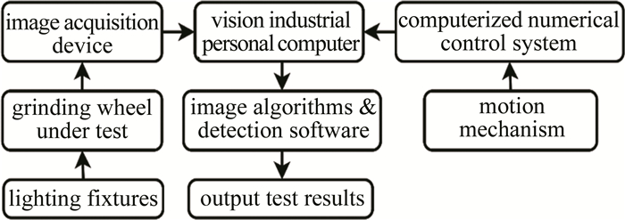
检测系统主要由图像采集部分、砂轮激光修整机视觉装夹运动部分、数控系统通讯和工控机及软件算法构成。图像采集部分由工业相机、工业相机镜头和照明光源三大组件组成。工业相机选用的是MV-CH120-10TM,具有1200万像素,负责采集和传输图像;镜头选用的是WKLT-40-100双侧远心镜头,负责物体成像;光源选用的是MHCL-65H-65-B远心平行光源和配套控制器,负责提升图像质量。视觉装夹运动部分负责将图像采集部分的硬件安装到砂轮激光修整机上,同时实现对焦和增加测量范围的功能,如图 1所示。工控机负责图像采集控制、机床通讯、检测软件运行等。检测系统示意图整体架构设计如图 2所示。
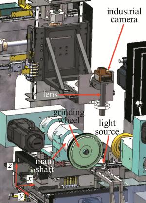
Figure 1. Visual clamping motion section
Figure 2. Overall architecture of the detection system
-
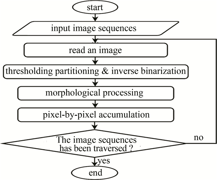
多轮廓合成轮廓检测方法的技术路线如图 3所示。待测砂轮安装在修整机主轴上,视觉工控机与修整机数控系统通讯软件读取主轴角度,主轴每转过一定角度,软件控制相机采集一张照片,直到砂轮旋转一周,得到砂轮完整的圆周方向的轮廓图像序列。对轮廓图像序列进行预处理,增强轮廓特征并生成二值图像。再将二值图像序列合成为带像素频率信息的轮廓频率图像,在轮廓频率图像中选取一定灰度区间中的像素,提取出轮廓波动带,最后基于轮廓波动带, 实现轮廓尺寸测量。
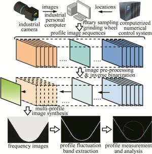
Figure 3. Profile detection method
1.1. 检测系统
1.2. 检测方法

-
本文中的轮廓检测算法需要基于圆周方向多个截面的轮廓图像,多轮廓图像合成算法是其核心,合成后的频率图像是后续检测和试验的基础。检测算法整体设计如图 4所示。
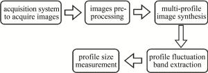
Figure 4. Key algorithms for detection systems
-
引导滤波是近年来流行的新的保边滤波算法,能在去除大量噪点的同时保留砂轮轮廓边缘细节,避免梯度反转现象,提高检测精度,它假设图像内存在局部的线性关系,认为图像是非解析的2维函数,但在局部可以用解析的线性函数来表达[19],如下式所示:
式中: qi表示滤波输出图像q的值;Ii为引导图像I (可以是原始图像)的值;Qk为第k个局部窗口;ak和bk在第k个局部窗口的常量系数。
对式(1)求导可得∇qi=ak∇Ii,如果引导图像中出现边缘,则输出图像q中也存在边缘,故可以实现边缘保留。求解式(1)中ak和bk的值,为了减少失真,使用均方误差代价函数M(ak, bk) 进行优化,如下式所示:
式中: ε为补偿系数;pi为原始图像p的值。
转化为最优化问题,即使式(2)的值最小,使用最小二乘法可计算ak和bk的值分别为:
式中: |Q|为窗口像素数;σk和μk为函数标准差和均值;p为第k个局部窗口内像素灰度均值。
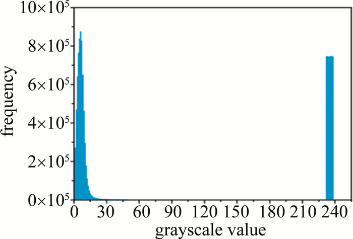
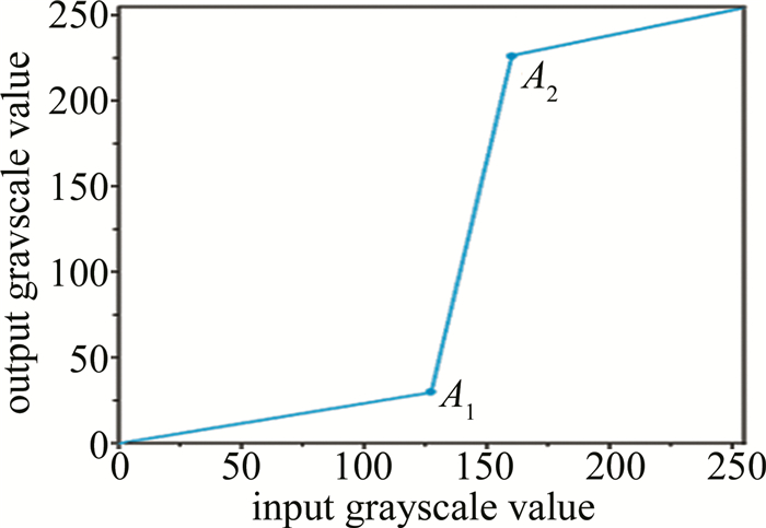
为了提高图像中背景和砂轮投影的对比度,突出砂轮轮廓特征,方便后续处理,采用直方图均衡改善图像中灰度的分布[20-21],增强局部的对比度,而不影响整体的对比度。砂轮轮廓图像的直方图如图 5所示。根据砂轮轮廓图像特征和此处对比度增强的需求,本文中图像增强使用分段线性变换,其变换曲线如图 6所示,图中两个锚点的位置可根据实际图像进行微调。

Figure 5. Histogram of grinding wheel images

Figure 6. Segmented linear transformation curve
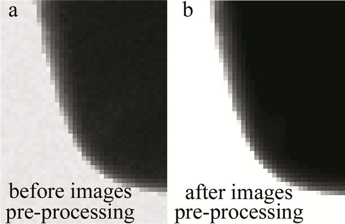
轮廓图像经过上述图像滤波和图像增强的预处理后,其效果如图 7所示。
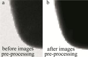
Figure 7. Images pre-processing effect
-
针对传统视觉检测中单一截面不能反映砂轮全域轮廓信息、检测精度差的问题,本文作者提出了一种基于圆周方向多截面轮廓图像合成的检测方法,算法的典型流程如图 8所示。
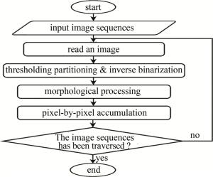
Figure 8. Profile synthesis algorithm flow chart
-
预处理后的轮廓图像背景和砂轮轮廓在图像中的灰度差异较大,因此可以通过阈值分割判定轮廓边缘[22]。本文中使用一个全局阈值将砂轮的轮廓图像划分为背景和砂轮轮廓两个特征,且预处理后的图像亮度分布均匀。在全局阈值分割过程中,将砂轮本体部分的像素灰度值置为1,将背景部分的像素灰度值置为0,即反二值化操作,其数学表达式如下:
式中: f0(x, y)为输入图像(x, y)点的灰度值; G0(x, y)为输出图像(x, y)点的像素值; T0为全局分割阈值。
按照上述方法进行阈值分割和反二值化的效果如图 9所示。
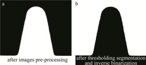
Figure 9. Effects of thresholding segmentation and inverse binarization
-
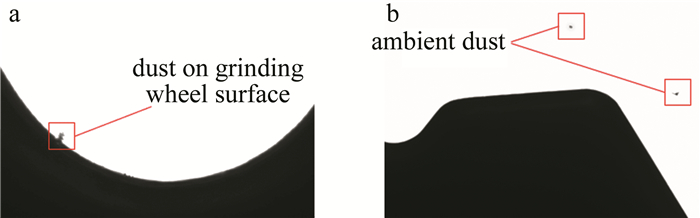
本文中通过开运算形态学操作,减少轮廓图像中的干扰杂点[23],如吸附在砂轮表面和镜头表面的灰尘和毛絮,如图 10所示。
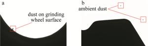
Figure 10. Impurity interference in profile images (zoom)
开运算由是图像膨胀和图像腐蚀两个基本操作的组成, 其数学表达式为:
式中: e代表结构元; (x, y)为结构元锚点的位置; (x′, y′)为结构元内值为1的元素相对其锚点的位置; G1(x, y)、G2(x, y)为输出图像; f1(x, y)为输入二值图像。
-
经过二值化和形态学处理后的图像中,像素值为1的位置对应砂轮实体,像素值为0的位置为背景。多轮廓图像合成算法即计算图像序列中图像像素位置砂轮实体出现的频次,得出轮廓频率图像。本文中检测系统设计的多轮廓图像合成算法有两种场景,如图 11所示。一种是砂轮旋转一圈采集一组图像序列然后进行静态合成,另一种是砂轮持续旋转实时对砂轮轮廓进行旋转采样并进行动态合成。
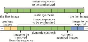
Figure 11. Two kinds of profile images synthesis scenes
静态合成算法只需要对一组圆周方向采样的砂轮轮廓图像转为二值图像序列,然后对序列中的图像相同像素位置求和即可。静态合成算法的数学表达式为:
式中: N为输入二值化和形态学处理后的图像序列; hj(x, y)为输入序列中第j张图像二值反转和形态学处理后(x, y)点的像素值; F1(x, y)为合成后的频率图像(x, y)点的值。
动态合成算法是在实时图像序列中动态合成最新的n张图像。算法处理流程为:每采集一张图像先进行二值化和形态学处理,实时图像序列中第1张~第n张图像的合成与静态合成算法一致,实时序列中第n+1张图像的合成需要先将动态序列第n+1张图像累加到频率图像中,然后频率图像减去第1张图像,则得到第2张~第n+1张的合成频率图。以此类推,在动态累加最新图像第j张到频率图像时,要减去第j-n张图像。动态合成算法的数学表达式为:
式中: n为合成窗口大小; hj(x, y)为输入序列中第k张图像二值反转后(x, y)点的像素值; hj-n(x, y)为输入序列中第j-n张图像二值反转和形态学处理后(x, y)点的像素值; F2(x, y)为输出频率图像(x, y) 点的值。
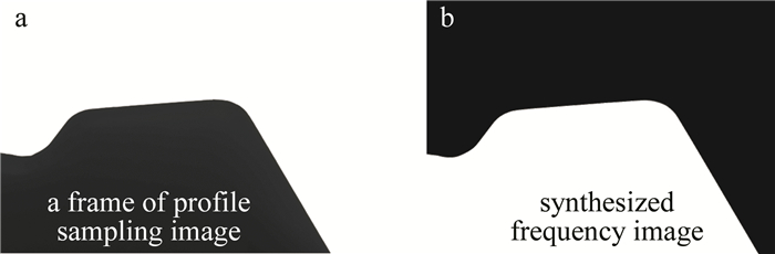
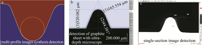
砂轮圆周方向采样的轮廓图像序列经过多轮廓图像合成算法处理后的效果如图 12所示。图 12a图是轮廓图像序列中的某一帧; 图 12b图是256张轮廓图像合成后的频率图像。

Figure 12. Effect of profile images synthesis algorithm
-
多轮廓图像合成后生成的频率图像本质上是一张灰度图,将频率图像进行局部放大,如图 13所示。频率图像中像素的值表示轮廓图像序列中该像素为砂轮实体的次数。本文作者将像素值为0的像素定义为绝对背景,即序列中所有的轮廓图像上该像素均对应背景;将像素值为图像序列长度的像素定义为绝对砂轮实体,即序列中所有的轮廓图像上该像素均对应砂轮实体;将频率图像中背景和砂轮轮廓之间的灰度过渡像素定义为轮廓波动带,轮廓波动带反映了圆周方向砂轮轮廓的综合信息。
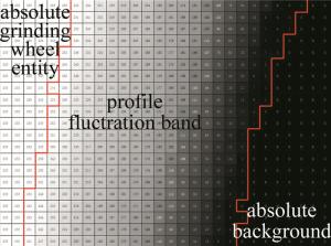
Figure 13. Frequency image partial zoom
为了简化后续的检测算法流程,先将频率波动带从频率图像中提取出来。由轮廓波动带的定义和上述分析可知,频率图像中灰度在一定范围内的像素即为轮廓波动带,因此使用阈值分割即可实现轮廓波动带的提取。此处的阈值分割数学表达式为:
式中: v(x, y)为轮廓波动带图像中(x, y)的值;F(x, y)为频率图像(x, y)点的值,静态合成时等于F1(x, y),动态合成时等于F2(x, y);T1为阈值区间下边界;T2为阈值区间上边界。
经实验,若m为图像序列的长度大小,在区间上边界阈值为0.005 m~0.02 m且区间下边界阈值为0.99 m~0.999 m时,轮廓波动带的精度较高。轮廓波动带提取的效果如图 14所示。
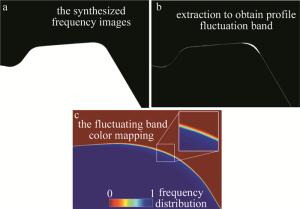
Figure 14. Profile fluctuation with extraction effect
-
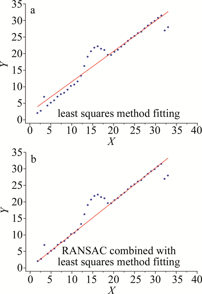
成形砂轮轮廓通常由直线段和圆弧段组成。通过对从频率图像中提取得到的轮廓波动带最外侧边缘拟合,可以测量砂轮的最外侧轮廓。相较与传统的单一图像检测方法,它能更真实地反映砂轮磨削工件复映的轮廓。但是,轮廓波动带边缘可能存在一些异常凸起和凹坑,轮廓边缘可能会出现部分随机离群噪点,这对直线和圆弧的拟合算法的鲁棒性提出一定的要求。因此,本文中使用随机抽样一致算法(random sample consensus,RANSAC)结合最小二乘法进行特征拟合,计算流程如下[24]:(a)随机从原始数据集S中取出s个元素,s个元素刚好能确定待求数学模型,求解待求模型的假设模型;(b)根据步骤(a)中得出的假设模型,计算数据集中所有点的残差E,将残差小于最低残差阈值t的点加入内点集Si;(c)如果内点集Si的大小大于设定阈值T,使用内点集Si进行最小二乘法拟合,并结束;(d)如果内点集Si的大小小于设定阈值T,则重复上述3个步骤;(e)达到最大循环次数N后,取N次循环中最大的内点集Si进行最小二乘法拟合。
上述过程中s和E参数由被拟合的特征类型决定,对于直线拟合,两点即可确定一条直线,故在RANSAC中s=2,残差E为数据集中点到假设直线的距离,数学表达式为:
式中: a, b和c为假设直线模型ax+by+c=0的参数; (xi, yi)为点集中第i个点的坐标。
对于圆和圆弧拟合,3点即可确定一个圆,故在RANSAC中s=3,残差E为数据集中点到假设圆的距离,数学表达为:
式中:x0, y0和R为假设圆模型(x-x0)2+(y-y0)2=R2的参数。
最大循环次数N可由理论推导,假设原始点集中内点的占比为p,则ps表示取s个点都是内点的概率,1-ps表示取s个点至少有一个为外点的概率,即单次采样失败概率,(1-ps)M表示M次循环采样均失败的概率,1-(1-ps)M则表示M次循环采样至少一次成功的概率。因此,假设采样成功率为w,则最少循环次数为ln(1-w)/ln(1-ps)。若假设点集中内点占比为0.9,采样成功率要求为0.99,则拟合直线时最大循环次数N=3,拟合圆弧时最大循环次数N=4即可。
内点集样本数达标阈值T和最低残差阈值t对算法的鲁棒性有很大影响,需要根据使用场景确定。经实验,在本文的场景中,内点集样本数达标阈值T为原始数据集S大小的0.9倍,最低残差阈值t=30时,有较好的拟合效果。如图 15所示,横纵坐标X和Y的数值表示砂轮V槽轮廓中的直线部分的一组点在2维平面的位置。对比直接最小二乘法,结合RANSAC的最小二乘法对离群点有更好的抗干扰性,符合本文作者预期设计。
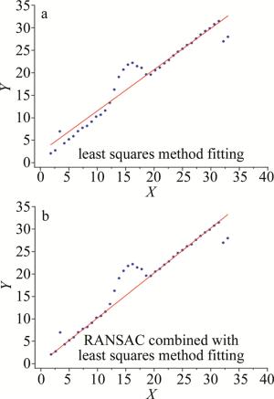
Figure 15. Comparison of fitting effects
2.1. 图像预处理算法
2.2. 多轮廓图像合成算法
2.2.1. 阈值分割和反二值化

2.2.2. 形态学处理
2.2.3. 多轮廓图像合成

2.3. 轮廓波动带提取


2.4. 轮廓特征测量
-
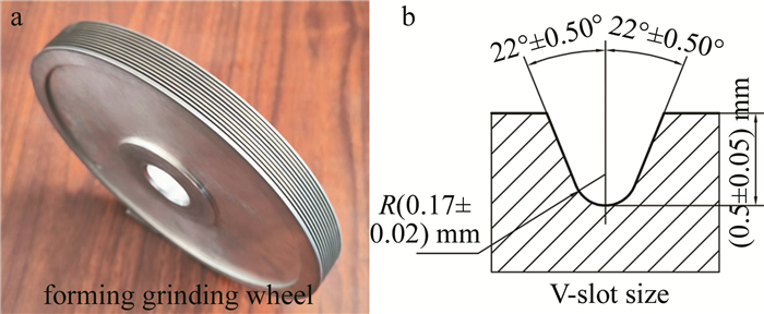
本实验中选用凹V型成形砂轮作为被测对象,如图 16a所示,其轮廓形状尺寸如图 16b所示。轮廓具有直线和圆弧特征,是最基本的成形砂轮轮廓,适合作为本文中的验证对象。
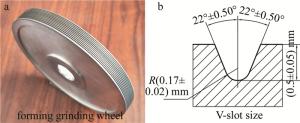
Figure 16. Concave V-slot forming grinding wheel and dimensional situation
离线检测时,需要先使用砂轮激光修整机床上的磨削复映装置夹持复映板材进行磨削,磨削复映机构如图 17所示。通过向负方向进给磨削复映装置的进给机构P轴,即可在复映板材上复映出砂轮的轮廓。
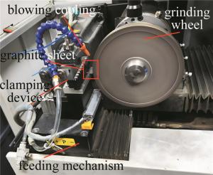
Figure 17. Grinding remapping device
为了减少磨削复映板材时砂轮自身的磨损,以及提高磨削效率,本实验中所用复映板材为细石墨板,实物图如图 18所示。同时石墨具有良好的耐热、耐压和润滑性,较适合干式磨削。本文中所选用的石墨板尺寸为30 mm×30 mm×3 mm,纯度大于99.5%,密度为1.82 g/cm3,肖氏硬度为35HS,平均颗粒直径10 μm。磨削石墨试片时,砂轮线速率为20 m/s,进给速率为0.1 mm/min,冷却方式为吹起冷却。
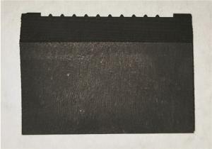
Figure 18. Graphite sheet
对复映有砂轮轮廓的石墨板,采用超景深显微镜的平面测量功能进行尺寸检测,具有最大20倍的光学放大倍率,搭配正面照射和背面照射双光源,支持全自动对焦、平面测量、3维测量等功能,满足高精度离线检测石墨片需求。
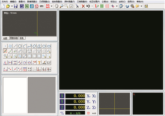
视觉单一截面检测法与本文作者提出的多轮廓图像合成检测法都是通过在线检测平台获取图像,如图 19所示。视觉单一截面检测对照实验时,使用已有的影像测量软件进行静态检测,其主界面如图 20所示。该软件已广泛应用于多款精密影像测量仪设备,支持图像实时测量、自动边缘拟合、几何标注等功能,具有良好的测量精度。
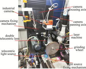
Figure 19. Online detection platform
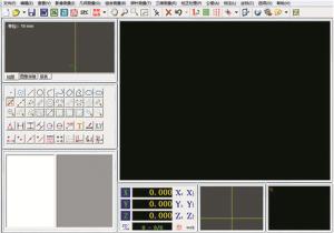
Figure 20. Image measurement software main interface
-
实验中以凹V型槽成形砂轮作为实验对象,使用砂轮激光修整机床的纳秒脉冲激光修整其轮廓形状,修整完成后分别使用磨削复映检测法、视觉单一截面检测法和本文作者提出的多轮廓图像合成检测法对砂轮上多个V型槽的轮廓尺寸进行检测,对比几种方法的检测结果,验证本文中检测系统的精度。
-
经过标定保证检测精度之后,按照上述的试验方案,使用3种方法对成形砂轮轮廓8个V型槽进行检测,检测过程如图 21所示。
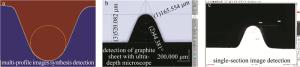
Figure 21. Three measurement methods detection process
分别测量了V型槽角度D、深度H和槽底圆弧半径R,测量结果分别如表 1、表 2和表 3所示。表中,单一截面检测法的测量结果为4个截面测量结果的平均值。检测效率上,计算完整检测单个V型槽的平均检测时间结果如表 4所示。
the number of V-slot the multi-profile images synthesis detection method/mm the single-section visual detection method/mm the grinding remapping detection method/mm 1 44.213 44.156 44.281 2 44.087 43.915 44.042 3 44.245 44.323 44.203 4 44.076 44.031 44.109 5 44.070 44.264 44.115 6 44.208 44.344 44.293 7 44.168 44.199 44.156 8 44.092 43.984 44.067 Table 1. Detection results of V-slot angle D
the number of V-slot the multi-profile images synthesis detection method/mm the single-section visual detection method/mm the grinding remapping detection method/mm 1 0.5251 0.5274 0.5183 2 0.5294 0.5396 0.5206 3 0.5342 0.5362 0.5299 4 0.5297 0.5373 0.5222 5 0.5300 0.5450 0.5255 6 0.525 0.5338 0.5177 7 0.5229 0.5287 0.5197 8 0.5281 0.5471 0.5207 Table 2. Detection results of V-slot depth H
the number of V-slot the multi-profile images synthesis detection method/mm the single-section visual detection method/mm the grinding remapping detection method/mm 1 0.1664 0.1611 0.1749 2 0.1624 0.1492 0.1686 3 0.1586 0.161 0.1672 4 0.1621 0.1566 0.1729 5 0.1597 0.1584 0.1671 6 0.1638 0.1571 0.1717 7 0.1662 0.1623 0.1706 8 0.1642 0.1528 0.1712 Table 3. Detection results of V-slot bottom arc radius R
the multi-profile images synthesis detection method the single-section visual detection method the grinding remapping detection method time spent/s 30 20 360 Table 4. Detection efficiency
-
3种特征检测结果中,多轮廓合成检测法的检测结果与磨削复映检测法更为贴近,而单一截面检测法的结果存在较大的随机波动。在V型槽深度的检测中,多轮廓合成检测和单一截面检测的结果普遍偏小;在底部圆弧半径的检测中,多轮廓合成检测和单一截面检测的结果普遍偏大,这是直接测量和间接测量之间的误差。一种原因可能是对石墨板进行磨削时,受石墨板的弹性变形和磨削过程热膨胀等因素影响,石墨板上复映的轮廓与砂轮轮廓不一致,产生固定误差; 另一种推测是砂轮表面未清理干净,仍有细小灰尘毛絮等附着物,同时砂轮轮廓存在不可避免的散射和反射,导致了最终采集的轮廓图像与实际轮廓之间存在误差。本文作者以工业界普遍认可的磨削复映法检测结果为基准,分别计算了单一轮廓检测和多轮廓检测两种方法的检测误差值,结果如表 5所示。
detection features detection methods the number of V-slot 1 2 3 4 5 6 7 8 angel/(°) the single-section visual detection method -0.265 -0.157 0.16 0.122 0.169 0.071 0.043 -0.203 the multi-profile images synthesis detection method -0.082 0.065 0.091 -0.033 -0.105 -0.085 0.012 0.025 depth/mm the single-section visual detection method 0.0091 0.019 0.0063 0.0151 0.0195 0.0161 0.009 0.0264 the multi-profile images synthesis detection method 0.0068 0.0088 0.0043 0.0075 0.0045 0.0073 0.0032 0.0074 radius/mm the single-section visual detection method -0.0138 -0.0194 -0.0062 -0.0163 -0.0087 -0.0146 -0.0083 -0.0184 the multi-profile images synthesis detection method -0.0085 -0.0062 -0.0086 -0.0108 -0.0074 -0.0079 -0.0044 -0.007 Table 5. Detection errors
观察V型槽角度的检测误差,几组检测样本中,两种检测方法都有较大的偏差,其中多轮廓合成检测法与磨削复映检测法的测量值偏差相对较小,最大正负误差分别为+0.045°和-0.085°,而单一截面检测法的测量值偏差较大,最大正负误差分别为+0.149°和-0.127°。V型槽角度的测量通常是先对V型槽两侧边进行直线拟合,再计算两直线夹角,当直线长度较短时,直线的拟合精度较差,会导致角度测量结果偏差较大。
槽底深度的检测误差和底部圆弧半径检测误差都分别偏向一个方向,但多轮廓合成检测误差更小,且误差的变化范围小。而单一截面检测,由于是仅抽取砂轮某一个截面的轮廓进行检测,随机性很大,导致其误差更大,且误差变化范围也更大。两种方法检测误差的统计指标如表 6所示。
detection features statistical indicators the multi-profile images synthesis detection method the single- section visual detection method mean value/mm -0.0076 -0.0132 radius range/mm 0.0064 0.0132 variance 3.0925×10⁻⁶ 2.13×10⁻⁵ mean value/mm 0.0062 0.01506 depth range/mm 0.0056 0.0201 variance 3.36937×10⁻⁶ 3.92×10⁻⁵ Table 6. Statistical indicators of the detection errors
由于直接检测和间接检测有方法上的差异,检测结果存在固定偏差值,导致存在7 μm左右的平均误差,但测量误差的极差可以在一定程度上反映检测精度。多轮廓合成检测法的误差极差最大值为6.4 μm,单一截面检测法的误差极差最大值达到20.1 μm,多轮廓合成法误差范围约为单一截面检测的1/3,同时误差方差要小一个数量级。综上分析,本文作者提出的多轮廓合成检测法效率远超磨削复映法,与单一截面检测法效率接近;检测结果上,与磨削复映法虽然有所差异,但误差值相对稳定,可通过补偿进行改善,相较于单一截面检测法,本文检测方法的误差更小,且误差变化范围约为±3 μm,检测精度更高。
3.1. 实验对象及设备


3.2. 实验方案
3.3. 检测结果及分析
3.3.1. 检测结果
3.3.2. 结果分析
-
介绍了基于砂轮激光修整机床搭建的图像采集系统的组成和工作原理,通过分析砂轮激光修整的特点,提出了一种多轮廓图像合成检测方法,定义了轮廓波动带的概念。使用合适的图像预处理算法,分析多轮廓图像合成算法的实现,并从合成结果中提取轮廓波动带,进一步研究基于轮廓波动带的轮廓测量。通过对凹V型轮廓成形砂轮进行检测试验,与磨削复映法和单一截面检测法进行对比,结果表明:多轮廓图像合成检测方法的检测结果与磨削复映法的检测结果接近,检测效率大幅提升,由于直接检测和间接检测方法上的差异,存在固定误差值,但误差的变化范围较小,约为±3 μm,相较于单一截面检测法,多轮廓图像合成检测方法的检测误差显著下降,检测效率接近,同时稳定性更佳,符合预期设计。
随着未来硬件设备的更新和算法效率的提升,本方法可与生成式人工智能(artificial intelligence generated content,AIGC)技术融合。借助辅助生成方法,通过输入关键词或需求,将待检测轮廓图像的尺寸精度和轮廓信息全部识别和提取出来,甚至形成专门的凹V型轮廓砂轮的数据集进行增强学习,进一步提高检测效率和精度,降低检测成本,但是要注意评判最终结果的真实性。
 DownLoad: