 Map
Map


HTML
-
随着科学技术的飞速发展,材料的服役条件要求高、失效问题严重引起了业界的高度关注[1-2]。激光熔覆技术具有热影响区小、热源集中、对材料不会造成影响[3-4]等优点,已广泛用于材料的失效修复[5]。但激光熔覆快速熔化和凝固过程会产生较大的残余应力,缩短材料的服役寿命,因此,降低熔覆过程中的残余应力是加速激光熔覆技术在工程领域应用的重中之重[6]。过去数十年里,已有大量关于如何释放涂层中残余应力的研究[7-8]。PARK等人[9]使用了热处理方法来释放材料中的残余应力,结果表明,经过700 ℃处理后,残余应力降低了50%。ROEHLING等人[10]研发出了使用发光二极管照射来释放涂层中的残余应力的新方法。MARTINEZ HURTADO等人[11]研究了两种可用于缓解激光熔覆件残余应力的手段,激光冲击强化(laser shock peening,LSP)和焊后热处理(post-weld heat treatment,PWHT)技术, 结果表明,LSP通过对材料表面进行冲击促进残余压应力的产生,PWHT在恢复韧性的同时也能消除一定的应力。以上提到的方法在降低涂层残余应力方面虽然有一定的效果,但是这些方法工艺复杂、成本高,不适合大批量生产。
Fe-Mn-Si系形状记忆合金可通过其特有的应力自适应特性释放残余应力,已有较多研究学者探索了这一特性在激光熔覆中的实际应用效果,并得到了良好的反馈。XU等人[12]利用激光熔覆技术熔覆Fe-Mn-Si-Cr-Ni形状记忆合金,极大地降低了涂层的残余应力。JU等人[13]在AISI 304#钢表面制备了Fe-Mn-Si形状记忆合金涂层,涂层表面的残余应力低于304不锈钢试件。事实证明,形状记忆合金涂层在降低熔覆残余应力方面有较好的应用前景。
然而,激光熔覆技术的广泛应用要求涂层不仅要具备低残余应力,还需兼备良好的综合性能,如硬度、耐磨性和耐蚀性等。本课题组前期为了改善形状记忆合金涂层的硬度和耐腐蚀性,使用了压电陶瓷、Ti、WC和Nb进行掺杂改性,硬度和耐腐蚀性有了一定的提升,但是离实际应用仍有一定差距[14-16]。有“工业维生素”之称的稀土元素在激光熔覆涂层性能提升方面具备很大优势[17-18],它能细化晶粒,将粗结构转化为细枝结构以及阻碍位错运动,并减少涂层的裂纹, 提升其塑韧性、显微硬度、耐磨性及耐蚀性等性能[19-25]。JIN等人[26]研究了稀土元素对刷镀技术制备的Fe基涂层残余应力的影响,发现稀土元素的加入使镀层中的残余应力由拉应力转变为压应力,涂层的表面形貌更致密均匀,裂纹和杂质减少。在添加的La、Pr和Ce 3种稀土元素中,La对镀层的表面形貌和残余应力的影响最为明显。WANG等人[21, 27]在镍基合金涂层中加入La2O3和CeO2,获得了致密的显微组织,稀土氧化物的掺杂降低了涂层在基材中的稀释率,并促使涂层生成了新相。CEHN和SONG等人[28-29]探究了CeO2对激光熔覆层的性能影响,结果显示,CeO2能有效细化晶粒,提高硬度。在多种稀土氧化物中,La2O3因与其它稀土氧化物相比,更有利于提高硬度、降低摩擦系数、减少磨损和夹杂物数量等[19, 30],广受研究者青睐。
为了进一步改善形状记忆合金涂层的性能,本文作者在42CrMo中碳钢表面熔覆制备Fe-Mn-Si形状记忆合金复合涂层,并在涂层中掺杂不同质量分数的La2O3,采用X射线衍射(X-ray diffraction,XRD)、维氏硬度计、摩擦磨损仪、电化学工作站和残余应力测试仪研究了La2O3对涂层组织结构与性能的影响。
-
实验基材为42CrMo中碳钢,激光熔覆材料为掺杂La2O3(质量分数w分别为0.000, 0.003, 0.006, 0.009, 0.012)的Fe-Mn-Si形状记忆合金(shape memory alloy, SMA)粉末(化学成分如表 1所示)。本实验在25 ℃室温下进行,合金粉末经球磨机(QM-3SP2)干磨2 h后再真空干燥2 h得到,采用预置粉末法对合金粉末进行激光熔覆。
group Fe Mn Si Cr Ni La2O3 1 balance 0.420 0.090 0.210 0.105 0.000 2 balance 0.420 0.090 0.210 0.105 0.003 3 balance 0.420 0.090 0.210 0.105 0.006 4 balance 0.420 0.090 0.210 0.105 0.009 5 balance 0.420 0.090 0.210 0.105 0.012 Table 1. Chemical composition of Fe-Mn-Si shape-memory alloy powders doped with different mass fraction of La2O3
-
实验中采用光纤激光系统(见图 1)进行激光熔覆,激光功率为3000 W,矩形光斑尺寸为2 mm×10 mm,扫描速率为6 mm/s。将熔覆后的成品线切割成规则样品,经磨样、抛光、干燥等后,利用X射线衍射仪分析涂层物相组成,扫描范围为20°~90°,步长0.02°;用光学显微镜和JMS-7500F型发射场扫描电子显微镜观察样品显微组织;采用小负荷维氏硬度显微镜进行硬度测量,沿熔覆层横截面由涂层顶部到基材每隔100 μm测一个点,每个点在同一水平方向测量3次,取平均硬度作为该点硬度值;利用电化学工作站对样品耐蚀性进行测试,极化曲线动态扫描速率为0.01 V/s,电位扫描范围位-2 V~2 V,阻抗谱测试中扫描频率范围为1×10⁻² Hz~1×10⁵ Hz。利用高速往复摩擦试验机测试基材及涂层的耐磨性,磨球材质为Si3N4,施加的载荷为10 N,往复速率为500 r/min,测试时间为15 min,并使用扫描电子显微镜和白光干涉仪对磨损后的试样表面形貌进行磨损机理分析;采用Stress-X残余应力系统对样品表面残余应力进行测量,X射线阳极管采用Cr靶Kα射线,2θ衍射角为128°,入射角Ψ分别为0°、±7.5°、±15°、±22.5°、±30°,单次曝光时长10 s。
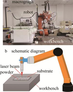
Figure 1. Laser cladding equipment
1.1. 材料
1.2. 实验方法
-
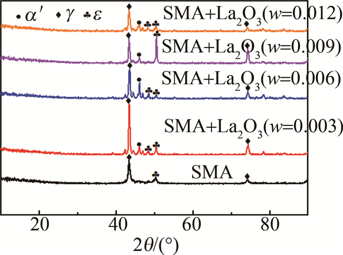
图 2为掺杂不同质量分数La2O3复合涂层的XRD结果图。纯SMA涂层中同时存在γ奥氏体相与ε马氏体相,添加La2O3后,涂层由γ、ε、α′马氏体三相组成。析出相α′马氏体可作为应力诱导马氏体的成核点,通过产生弹性应变场促进肖克莱不全位错在退火过程中的向后运动改善合金的形状记忆效应。SMA合金粉末熔覆过程中,熔覆层内骤冷、骤热产生的残余应力诱发ε马氏体由层错形核,经肖克莱不全位错的扩展而长大[19],促使γ→ε转变,导致涂层中同时存在γ奥氏体和ε马氏体两相[31],有效地减小了涂层中的残余应力,抑制裂纹萌生。

Figure 2. XRD of the composite coating doped with different content of La2O3
-
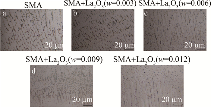
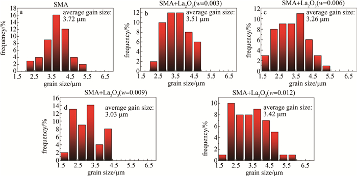
图 3为掺杂不同质量分数La2O3复合涂层的金相显微组织图。图 4为该涂层对应不同La2O3质量分数下的平均晶粒尺寸。与纯SMA涂层的显微组织相比,掺杂La2O3的合金涂层晶粒更细小,组织分布更均匀。这是因为,稀土元素具有较大的活性和原子半径,涂层表面上位于晶界的La在晶粒生长时对晶界运动产生拖拽作用,抑制相和晶粒的生长,从而细化涂层的微观结构[27, 30]。当La2O3的w=0.009时,平均晶粒尺寸为3.03 μm,微观晶粒由等轴晶和柱状晶组成,涂层的强度和塑性均得到改善。
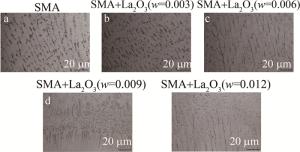
Figure 3. Microstructures of the composite coating doped with different mass fraction of La2O3
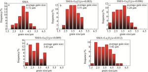
Figure 4. Average grain size
-
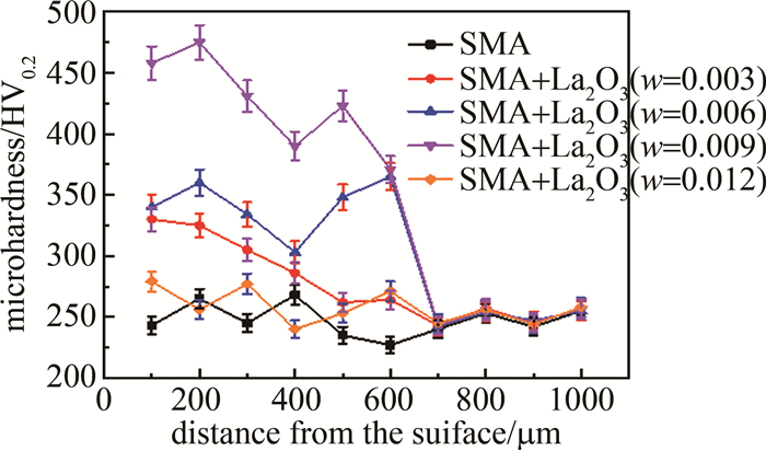
图 5为复合涂层的显微硬度曲线图。SMA涂层中掺杂La2O3后,涂层整体硬度得到显著提升,且La2O3的w=0.009时达到最大的平均硬度值454.7 HV0.2。由图 4可知,掺杂La2O3的复合涂层晶粒尺寸显著减少。根据Hall-Petch公式[32],晶粒的细化会增加晶界数量从而阻碍位错运动,此时,在晶界处发生位错缠结,材料的塑性变形被阻碍,表面强度提高,Fe-Mn-Si/La2O3复合涂层的显微硬度增大。
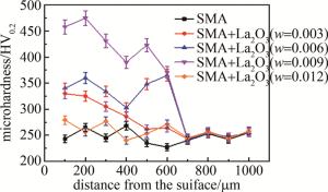
Figure 5. Microhardness curves of the composite coating
式中: σs是材料的屈服强度;σ0是常数,大体相当于单晶体的屈服强度;k是晶界对强度影响程度的常数;d是晶粒大小。
但当La2O3的w达到0.012时,复合涂层与SMA涂层的硬度值曲线趋于重合。这是因为La2O3质量分数增加到一定值时,复合涂层表面发生了聚集导致结构稳定性变差,降低了涂层硬度[33]。结果表明,La2O3的适量掺杂可有效提高涂层的显微硬度。
-
图 6为复合涂层的摩擦系数曲线和磨损质量对比图。随着时间的延长,图 6a中涂层的摩擦系数(coefficient of friction, COF)有一段急速上升期,稳定磨损区的磨擦系数曲线在某一纵坐标范围内上下小幅度浮动,图 6b中的柱状磨损质量对比图中纯SMA涂层磨损质量达到了0.779 mg,w=0.009的La2O3复合涂层具有最小的磨损质量0.237 mg,掺杂La2O3的复合涂层的耐磨性都有不同程度的提高。结合图 2中的XRD图谱可以看出,该耐磨性的提高一定程度上得益于纳米孪晶的马氏体[34]。此外,La2O3的六边形层状结构使SMA涂层的平面间距变大,加剧了润滑作用,因而复合涂层受到的摩擦阻力较小,耐磨性得到提升[19, 35-36]。
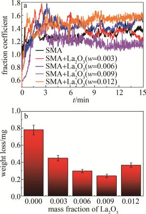
Figure 6. a—friction coefficient curves of composite coating b—wear quality contrast diagram of the composite coating
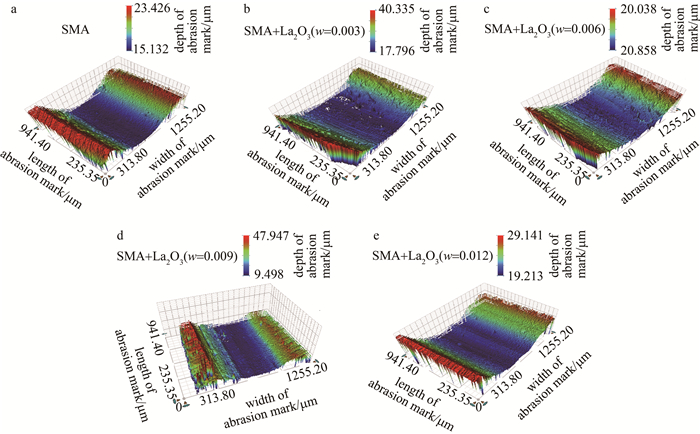
图 7为复合涂层的磨损显微形貌图。纯SMA涂层的磨痕较窄而深,添加了w为0.003和0.006的La2O3的复合涂层磨痕中有犁沟状痕迹,为典型的磨粒磨损; w为0.009和0.012的La2O3复合涂层的磨痕无明显犁沟,表现出粘着磨损的特征,且w为0.012的La2O3的SMA涂层磨痕不平整,说明耐磨性开始下降。图 7b和图 7c中的犁沟痕是由磨球接触到涂层表面发生相互作用后,涂层表面会掉落一部分硬质颗粒,硬质颗粒在磨球的推动下产生犁地作用得到的。图 7d中,La2O3的细晶强化和弥散强化作用有效地阻止了磨球微凸体的嵌入和犁耕效应[33]。而图 7e中,La2O3掺杂过量,过量的La2O3颗粒发生团聚,熔池的流动性降低,生成的稀土氧化物在晶间形成夹杂物,在磨损过程中,这些夹杂物在摩擦副的往复作用下极易被切削掉,从而降低涂层的耐磨性[34, 37]。
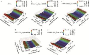
Figure 7. Wear micrographs of composite coating
-
图 8a为复合涂层在3.5% NaCl中的极化曲线。La2O3的w分别为0.003、0.006和0.009的腐蚀电位依次上涨,当w上涨到0.012时腐蚀电位降低,接近SMA涂层。表 2为基材及4组复合涂层的电化学数值。自腐蚀电位Ec反映了材料的腐蚀倾向,该值越大, 材料的腐蚀倾向相对越小,而自腐蚀电流密度Ic反映了材料的腐蚀速率,该值越小, 材料的腐蚀速率越慢。基于此,分析表 2中自腐蚀电位与自腐蚀电流密度的变化趋势可以看出,La2O3的w在0.003~0.009范围内, 随着La2O3的增加,涂层的腐蚀倾向在逐渐变小;而w=0.012时, 涂层耐蚀性较差; w=0.009的La2O3的涂层具有最大的自腐蚀电位-0.843 V和最低的腐蚀电流4.287×10⁻⁷ A/cm2,其耐蚀性最好。结果表明,适量添加La2O3能提升记忆合金涂层耐腐蚀性,这可能是由于形成的稀土化合物填充晶界,增大晶界密度,从而使得腐蚀液不易通过晶界进入涂层内部导致基材腐蚀,起到提高材料耐蚀性的作用[38]。而当La2O3的w达到0.012时,涂层上的团聚现象加剧,La2O3的结块颗粒不断增大,由于表面结节之间存在较大间隙,导致涂层产生缺陷腐蚀[30]。并且,过多的La2O3容易在涂层中形成夹杂物[26],使得组织不均匀、涂层局部电位不等,从而加速腐蚀的进行。
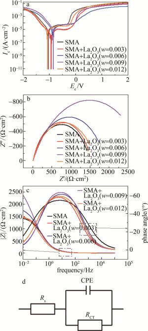
Figure 8. a—polarization curves of composite coatings b—Nyquist plots c—Bode plots d—equivalent electrical circuit curve
sample free corrosion potential Ec/V freecorrosion current density Ic /(A·cm-2) SMA -1.032 8.294×10⁻⁶ SMA+La2O3(w=0.003) -0.934 8.494×10⁻⁷ SMA+La2O3(w=0.006) -0.885 5.359×10⁻⁷ SMA+La2O3(w=0.009) -0.843 4.287×10⁻⁷ SMA+La2O3(w=0.012) -1.076 7.294×10⁻⁷ Table 2. Electrochemical values of the substrate and four groups of composite coating
Nyquist图(见图 8b)反映了涂层的电阻,Z′和Z″分别是阻抗的实部和虚部,半径的大小代表抗腐蚀能力的强弱。复合涂层在La2O3的w=0.009时半径最大,继续掺杂稀土,涂层半径变化不大,耐腐蚀效果不明显。图 8c中|Z|通常用于评价低频时涂层的抗腐蚀性能,图中曲线的变化趋势佐证了La2O3具备提高涂层耐蚀性的作用。单时间常数过程采用图 8d中的等效电路进行拟合,电路图中的元件Rs为溶液电阻,CPE(constant, phase, element)为恒相元件,RCT为电荷转移电阻。
图 9a~图 9c、图 9d~图 9f、图 9i~图 9k分别为La2O3的w为0.003、0.006、0.009时SMA/La2O3复合涂层的SME形貌图。从图中可以看出,涂层只有部分被腐蚀,腐蚀区存在许多网状的微孔结构、腐蚀坑,同时还存在亮白色的夹杂物。值得注意的是,腐蚀初始位置位于薄弱的晶界处以及存在夹杂物的地方,由于w=0.009时复合涂层存在更多的La2O3,晶粒细化作用更强,存在着更多更密集的晶界,因而更耐腐蚀。
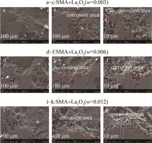
Figure 9. Corrosion morphologies of Fe-Mn-Si/La2O3 composite coating
-
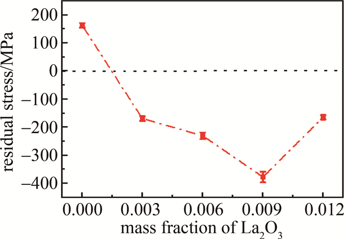
图 10为不同La2O3掺杂Fe-Mn-Si/La2O3复合涂层的残余应力变化曲线。La2O3的w在0.000~0.003范围内,残余应力由拉应力变为压应力;w从0.003~0.009变化时,残余压应力显著增加,涂层与基材的结合强度增强,涂层致密度和裂纹敏感性提升、开裂减少[39-42]。当La2O3的w=0.009时得到最大的压应力-378 MPa,此时涂层的断裂韧性得到增强[43]。根据研究[26]可知,稀土元素可通过抑制晶粒聚集以及减少杂质来影响残余应力,故而适量掺杂La2O3有助于残余应力的转换。但当La2O3的w增加到0.012时,La元素在晶界和晶内和其它元素发生反应生成稀土化合物,限制了相的生长,显著降低了SMA涂层的应力松弛效应,所以w=0.012时的残余压应力值仅为-165 MPa。整体而言,添加La2O3的涂层性能高于纯SMA涂层。
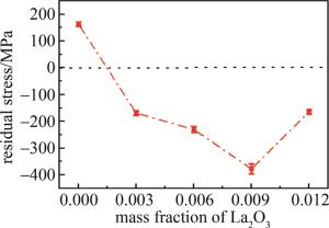
Figure 10. Residual stress curve of Fe-Mn-Si/La2O3 composite coating
2.1. Fe-Mn-Si/La2O3复合涂层的XRD分析
2.2. Fe-Mn-Si/La2O3复合涂层的显微组织
2.3. Fe-Mn-Si/La2O3复合涂层的显微硬度
2.4. Fe-Mn-Si/La2O3复合涂层的摩擦性能

2.5. Fe-Mn-Si/La2O3复合涂层的耐蚀性


2.6. Fe-Mn-Si/La2O3复合涂层的残余应力
-
利用宽带激光熔覆技术,在42CrMo中碳钢表面制备了Fe-Mn-Si/La2O3复合涂层,并对涂层进行了XRD、显微组织、显微硬度、耐磨耐蚀以及残余应力测试。
(a) La2O3具有晶粒细化作用。纯SMA涂层的平均晶粒尺寸为3.72 μm,当La2O3的w=0.009时, 平均晶粒尺寸为3.03 μm,细化效果较为明显。
(b) w在0.003~0.009的范围内, Fe-Mn-Si/La2O3复合涂层的硬度和耐磨性与La2O3掺杂量呈正相关。La2O3的w=0.009时,涂层表面等轴晶和柱状晶粒混合组织显著提升了涂层表面的强塑性和耐磨性,摩擦磨损量为0.237 mg,仅为纯Fe-Mn-Si涂层的0.3倍。
(c) 适量的La2O3掺杂有利于提高材料耐蚀性。当La2O3的w=0.009时,涂层的自腐蚀电位为-0.843 V,相比纯Fe-Mn-Si涂层降低了18.31%。
(d) 激光熔覆过程中的La2O3掺杂有利于促进残余拉应力向压应力转换。w=0.009的La2O3/Fe-Mn-Si涂层具有最大的残余压应力-378 MPa, 此时,涂层的的断裂韧性得到增强,裂纹敏感性降低。
 DownLoad: