Advanced Search

ISSN1001-3806 CN51-1125/TN Map

Volume 43 Issue 3
Mar.  2019
Article Contents
Turn off MathJax

Citation:

Measurement method of resonance frequency for longitudinal resonant photoacoustic cells

  • Corresponding author: LU Rongjun, rjlu@seu.edu.cn
  • Received Date: 2018-05-21
    Accepted Date: 2018-07-18
  • Resonant frequency of a photoacoustic cell is one of its key parameters. In order to measure resonant frequency of a resonant photoacoustic cell quickly and accurately, a resonant frequency measurement method based on resonant acoustic spectroscopy was used to built a photoacoustic spectroscopy detection system and a resonant acoustic spectroscopy measurement system. The factors affecting the accuracy of measurement results were analyzed. Resonant frequency of the resonant photoacoustic cell was measured by the resonant acoustic spectroscopy method and photoacoustic signal intensity method respectively in the case of different gas concentrations. The experimental results indicate that the resonance frequency measured by the resonant acoustic spectroscopy method is independent of excitation voltage of the sound signal, distance and angle of sound source. Under the conditions of 5 different concentrations of acetylene(C2H2) gas, the maximum deviation of the resonant frequency between the resonance acoustic spectroscopy and photoacoustic signal intensity method is 1.1Hz. It is considered that the measured results of both the methods are consistent. The resonant acoustic spectroscopy method is simple, fast, reliable and accurate. It can be used to determine the resonant frequency of a photoacoustic cell.
  • 加载中
  • [1]

    ZHA Sh L, LIU K, GAO X M, et al. Acetylene detection based on resonant high sensitive photoacoustic spectroscopy[J]. Spectroscopy and Spectral Anaysis, 2017, 37(9):2673-2678(in Chinese).
    [2]

    IVASCU I R, MATEI C E, PATACHIA M, et al. Multicomponent detection in photoacoustic spectroscopy applied to pollutants in the environmental air[J]. Romanian Reports in Physics, 2015, 67(4):1558-1564.
    [3]

    YUN Y, CHEN W, WANG Y, et al. Photoacoustic detection of dissolved gases in transformer oil[J]. International Transactions on Electrical Energy Systems, 2008, 18(6):562-576.
    [4]

    SHI M K, HU B, YING H, et al. Research of photoacoustic spectroscopy effect of ethylene concentration detected by laser[J]. Laser Technology, 2016, 40(3):426-431(in Chinese).
    [5]

    LI L, XIE W M, LI H. Applications of photoacoustic spectroscopy in the field of modern biomedicine[J]. Laser & Optoelectronics Progress, 2012, 49(10):100008(in Chinese).
    [6]

    LI H, GAO Y, LIU H B, et al. High-speed and 128-channel muti-spectral photoacoustic tomography system for small animal[J]. Laser Technology, 2017, 41(5):669-674(in Chinese).
    [7]

    JIANG M, FENG Q L, WEI Y F, et al. Recent advance in miniaturization of photoacoustic spectroscopy gas sensor[J]. Laser & Optoelectronics Progress, 2015, 52(2):20006(in Chinese).
    [8]

    CHEN Y, GAO G, GAI T. Detection technique of ethylene based on photoacoustic sepctrocopy[J]. Chinese Journal of Lasers, 2017, 44(5):0511001(in Chinese).
    [9]

    HANSON R K, SPEARRIN R M, GOLDENSTEIN C S. Spectroscopy and optical diagnostics for gases[M]. New York, USA:Springer International Publishing Switzerland, 2016:208-210.
    [10]

    MA Y F, YU G, ZHANG J B, et al. Research on real-time trace gas detection system based on QEPAS[J]. Spectroscopy and Spectral Analysis, 2015, 35(11):3003-3006(in Chinese).
    [11]

    ZHANG X X, LI X, LIU H, et al. The quantitative detection of SF6 characteristic decomposition component H2S based on cantilever enhanced photoacoustic sepctroscopy[J]. Transaction of China Electrotechnical Society, 2016, 31(15):187-196(in Chinese).
    [12]

    LÜ Q X, LONG M D, LIU L W. Research on gas detector for hydrogen fluoride based on photoacoustic spectroscopy[J]. Environmental Science & Technology, 2016, 39(4):83-87(in Chinese).
    [13]

    VIJ D R. Handbook of applied solid state spectroscopy[M]. New York, USA:Springer Science Business Media, 2006:351-387.
    [14]

    CHEN J, YIN T Y, XU Z, et al. Detection of concrete damage using nonlinear impact resonance acoustic spectroscopy[J]. Industrial Construction, 2016, 46(1):95-99(in Chinese).
    [15]

    FANG J Q, LI H J, LEI Y P, et al. Experiment study on structure state identification by acoustic resonance spectrum method[J].Technical Acoustic, 2008, 27(5):196-197(in Chinese).
    [16]

    YANG X. Research on measurement technology of acoustic velocity in Seawater using acoustic resonance spectroscopy[D]. Changsha: National University of Defense Technology, 2008: 39-40(in Chin-ese).
  • 加载中
通讯作者: 陈斌, bchen63@163.com
  • 1. 

    沈阳化工大学材料科学与工程学院 沈阳 110142

  1. 本站搜索
  2. 百度学术搜索
  3. 万方数据库搜索
  4. CNKI搜索

Figures(8) / Tables(2)

Article views(7365) PDF downloads(27) Cited by()

Proportional views

Measurement method of resonance frequency for longitudinal resonant photoacoustic cells

    Corresponding author: LU Rongjun, rjlu@seu.edu.cn
  • Department of Instrumental Science and Technology, School of Instruments Science and Engineering, Southeast University, Nanjing 210096, China

Abstract: Resonant frequency of a photoacoustic cell is one of its key parameters. In order to measure resonant frequency of a resonant photoacoustic cell quickly and accurately, a resonant frequency measurement method based on resonant acoustic spectroscopy was used to built a photoacoustic spectroscopy detection system and a resonant acoustic spectroscopy measurement system. The factors affecting the accuracy of measurement results were analyzed. Resonant frequency of the resonant photoacoustic cell was measured by the resonant acoustic spectroscopy method and photoacoustic signal intensity method respectively in the case of different gas concentrations. The experimental results indicate that the resonance frequency measured by the resonant acoustic spectroscopy method is independent of excitation voltage of the sound signal, distance and angle of sound source. Under the conditions of 5 different concentrations of acetylene(C2H2) gas, the maximum deviation of the resonant frequency between the resonance acoustic spectroscopy and photoacoustic signal intensity method is 1.1Hz. It is considered that the measured results of both the methods are consistent. The resonant acoustic spectroscopy method is simple, fast, reliable and accurate. It can be used to determine the resonant frequency of a photoacoustic cell.

引言
  • 光声光谱检测技术(photoacoustic spectroscopy,PAS)是在美国科学家BELL于1880年发现的光声效应的基础上发展起来的。在光声光谱技术提出的早期,由于缺乏合适的光源和信号探测器,使得光声光谱技术的研究停滞不前[1]。20世纪60年代以来,随着激光器的出现、声传感技术和微弱信号检测技术的发展,光声光谱技术得到了长足的发展。该技术具有操作容易、抗干扰性强、检测灵敏度高、稳定性好、响应速度快、成本低等特点,广泛用于大气环境监测、电力设施故障在线检测、生命科学、临床医疗诊断等领域[2-7]

    在共振型光声光谱检测系统中,光声池作为气体产生光声效应的载体,其性能直接影响系统检测灵敏度。1阶纵向共振光声池的谐振频率和品质因数的理论计算值可根据传输线等效模型获得,但在实际应用中,因机械加工尺寸和实验环境的不同,理论值与实际值有偏差,一般需要实验来标定。传统的实验标定方法是通过改变入射光调制频率,逐个记录光声信号强度,再基于实测数据的Lorentz曲线拟合,得到光声信号最强点对应的调制频率即为谐振频率[8]。该方法只有在光声光谱检测系统全部部署完成,并能检测到微弱光声信号的条件下才能实现共振频率测量,检测难度较大,标定过程耗时长,当实验环境如温度、湿度改变时,需要重新标定,且采用曲线拟合的方法本身存在误差。

    本文中提出一种基于共振声谱法测量光声池共振频率的方法,自光声池加工伊始即可掌握该参量;对可能影响测量准确性的因素进行了实验分析;并在不同气体浓度的情况下,分别采用共振声谱法和光声信号强度标定法测量光声池的谐振频率,获得的结果一致,确定了该方法的有效性。

1.   基本原理
  • 光声光谱检测技术是一种直接测量物质因吸收光能而产生热能的光谱量热技术[9]。在密闭光声池内,气体分子吸收特定波长的光被激发到高能态,高能态分子的相互碰撞使部分受激分子通过无辐射弛豫返回基态,吸收的光能转变为热能,腔内气体受热膨胀产生声波。当入射光是周期性调制光时,产生的声波也呈周期性变化,通过传声器元件,如微音器、石英音叉、悬臂梁式声波传感器[10-11]等,检测声波的幅值就可以实现对气体浓度测量。

    在共振光声系统中,光声池对共振频率处的声波具有共振放大的作用,从而提高系统检测灵敏度。通常共振光声池采用1阶纵向结构,其共振频率f0可表示为[12]

    式中,v为气体中声速,Lc为谐振腔腔长。可见,光声腔谐振频率不仅与谐振腔腔长有关,还与声波传播介质有关。

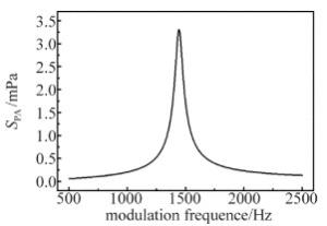
    图 1中给出了在谐振腔腔长为120mm时,光声信号SPA与调制频率的关系。因此,当调制频率与共振频率相等时,光声信号最强,当调制频率偏离共振频率较远时,光声信号将大幅度削弱。为提高光声信号强度和系统检测灵敏度,需要尽可能保证入射光调制频率与光声腔谐振频率一致。测量该参量是共振光声光谱检测的重要基础。

    Figure 1.  Relationship between incident light modulation frequency and photoacoustic signal (Lc=120mm)

  • 共振声谱法(resonance acoustic spectroscopy,RAS)是对入射声波激励下弹性物体共振频率的研究[13],共振频率是弹性物体固有的物理属性。在扫频信号声源的激振下,弹性材料必然有某些固有频率被显著激发,弹性物体因具有不同的物理属性,使得其具有不同的谐振频率。当该物体物理属性不发生改变时,其对应的谐振频率也不会改变,因此,可采用共振声谱法测量弹性目标物体的共振频率[14]

    共振声谱法根据激励信号的不同可分为稳态法和瞬态法[15]。通过对声波换能器施加一等幅扫频激励(稳态法)或一定带宽的脉冲激励(瞬态法),产生声波在声学谐振腔内传播,使得谐振腔各阶谐振模态被激发出来,腔体产生振动,对振动信号进行频谱分析,其中必定存在某一频率点,其对应的振幅最大,记录此频率及其振幅,即可获得该腔体的共振频率及共振振幅。稳态法采用等幅正弦扫频信号对腔体进行频率扫描,得出的共振频率与扫频信号的频率分辨率相关,具有较高的准确度,但测量速度较慢。瞬态法采用脉冲激励,响应速度快,但因为脉冲激励在不同频率点,激励信号强度不同,使得在识别共振声谱的共振频率时难度较大。在理论计算出初始谐振频率的基础上,本文中采用稳态共振声谱法完成光声池共振频率的测量,在该频率点附近使用等幅正弦扫频信号扫描腔体,快速寻找出准确谐振频率。

2.   实验系统设计
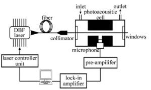
  • 本文中基于波长调制与二次谐波检测技术搭建的共振型光声光谱检测系统结构如图 2所示。采用实验室自制的波长调制信号源和激光器控制板对入射光进行波长调制后,经微型光纤准直器准直后入射到充满气体的光声池,待测气体吸收光能产生声波,声波经微音器转换为电信号并经前置放大器和锁相放大器,滤波放大处理后提取出吸收光谱。

    Figure 2.  Schematic structure of photoacoustic spectroscopy system

    光声池采用1阶纵向共振模式,气体进出口设置在两端的缓冲室中,以减少气体流动对光声信号检测的干扰,同时缓冲室可减少相干背景噪声。根据(1)式可知,当光声池几何尺寸确定后,可计算得出谐振频率。为尽可能提高系统检测灵敏度,需合理设计光声池的几何尺寸。综合考虑机械加工、激光光束准直难易程度,本文中采用导热性较好的金属铝作为光声池材料,其几何尺寸和谐振腔性能指标的理论计算值如表 1所示。

    buffer room r/mm buffer room l/mm resonant cavity R/mm resonant cavity L/mm resonant frequency f/Hz
    20 60 3 120 1443

    Table 1.  Dimensions and parameters of photoacoustic cell

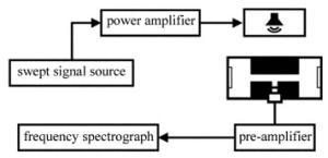
  • 本文中所搭建的共振声谱系统是在光声光谱检测系统基础上,增加一个声波激励模块构成的,声波激励模块包括音频功率放大模块(LM1875)和扬声器(Risym 4Ω/3W)。测量过程中,无需拆除光声光谱检测系统,只需将声波激励模块放置在光声池附近即可, 其结构如图 3所示。扫频信号发生器(Tektronix,AFG3102)产生正弦扫频激励信号,该激励信号经功率放大器放大后驱动扬声器,扬声器产生声波作用于充满待测气体的光声池;光声池受到声波激励后,会在内部产生声压信号,该信号经微音器转换为电信号并经前置放大电路放大;采用实验室自制的数据采集系统,采集前置放大电路的输出,并对采集的数据进行频谱分析,便可快速获得实验条件下光声池的谐振频率。

    Figure 3.  Schematic structure of resonance acoustic spectroscopy system

3.   实验结果与讨论
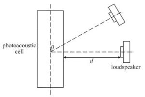
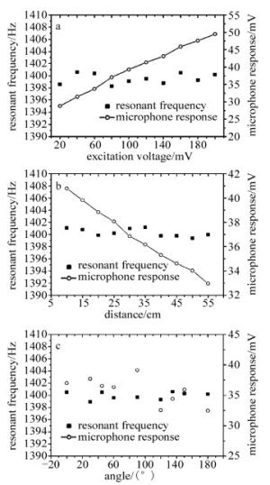
  • 在对充满不同浓度气体的光声池进行共振声谱谐振频率测量前,需要研究声源特性参量对谐振频率测量结果的影响,这些特性参量包括:声信号激励电压、扬声器与光声池距离、扬声器声波传播角度,目的在于对测量结果进行必要的检验[12]图 4为实际测试时扬声器与光声池相对位置的示意图。图中, θ为光声池轴向与扬声器声波传播方向的夹角,d为扬声器与光声池中心位置的距离。

    Figure 4.  Relative location between photoacoustic cell and loudspeaker

    表 1可知, 光声池谐振频率理论值为1443Hz,设置扫频信号发生器的扫频范围为1kHz~2kHz,扫描时间为10s(对应频率分辨率为0.1Hz),采用单一变量法,分别改变扬声器激励信号电压u、声源传播距离d、声源传播角度θ的情况下,测量光声池谐振频率,实验结果如图 5所示。

    Figure 5.  Impact of acoustic source characteristics on measurement results

    图 5a图 5b图 5c为分别改变u, d, θ时得到的实验数据。在u从20mV~160mV,d从10cm~50cm,θ从0°~180°变化时,光声池谐振频率基本不变,可见共振频率的测量结果不受u, d, θ的影响。微音器的幅度响应与u, d呈线性关系,这是因为激励信号幅值增大时,声源的振幅增大,微音器检测到的信号相应地增大;同理扬声器与光声池间距减小时,声波衰减减小,检测到的声波振幅增大,微音器输出相应增大。

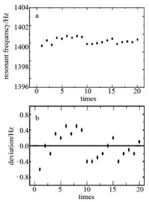
  • 为了验证共振声谱法的有效性,需要对谐振频率测量结果的可重复性进行测试。因周围环境噪音声谱复杂多变,这势必会对光声池谐振频率测量结果产生一定干扰,为了尽可能减少这种环境噪声干扰,选择了环境噪音小的时段,对光声池谐振频率进行重复测量。图 6a为重复测量20次的实验结果,图 6b为各次测量结果与均值之间的偏差。各次测量结果间偏差小于0.9Hz,可见该系统可重复性很好。

    Figure 6.  Repeatability measurement results of acoustic resonance spectroscopy

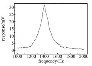
  • 往光声池中通入载气为N2的体积分数为5×10⁻⁵的C2H2气体,将扬声器置于d=10cm,θ=90°的位置,设置扫频信号幅值为100mV,扫频时间为10s,测得微音器的频率响应如图 7所示。图中数据为10个扫描周期平均后的结果,从图中可看出,在频率为1402.2Hz处,微音器输出信号最强,因此共振声谱法测得的光声池共振频率为1402.2Hz。

    Figure 7.  Frequency response of photoacoustic cell based on acoustic resonance spectroscopy method

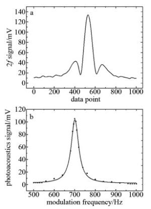
    基于搭建好的光声光谱气体检测系统,采用波长调制与2f信号检测的方法提取2f信号,图 8a即为调制频率在700Hz时检测到的2f信号。改变调制频率,记录2f信号幅值,再对各个调制频率点2f信号幅值(即光声信号强度)作Lorentz曲线拟合,结果如图 8b所示。根据拟合参量,可计算出拟合曲线最高点对应的调制频率为700.8Hz,因此光声池谐振频率为1401.6Hz。

    Figure 8.  Resonant frequency measurement results based on photoacoustic signal amplitude

    为了验证两种方法测量结果的一致性,采用两个七星华创量程分别为50SLM和300SCCLM的质量流量计,另配置了4种不同体积分数的气体,分别用两种方法来测量光声池共振频率,测量结果如表 2所示。f0为共振声谱法测量结果,f0′为光声信号强度标定法得到的测量结果。由表 2可知,光声腔谐振频率随腔内C2H2气体体积分数增加而略微增大,这是因为随着C2H2气体体积分数增加,光声池内气体总体密度减小,声波传播速度增大,从而使得共振频率增大[16];对比两种方法测得的实验结果,在气体体积分数相同情况下,两种方法测量结果最大偏差为1.1Hz,两种测量方法结果具有较好的一致性。

    volume fraction of C2H2 f0/Hz f0′/Hz
    1×10⁻⁵ 1397.8 1396.7
    2×10⁻⁵ 1398.5 1398.9
    3×10⁻⁵ 1400.2 1400.0
    4×10⁻⁵ 1401.4 1401.0
    5×10⁻⁵ 1402.2 1401.6

    Table 2.  Measurement results of resonant frequency at different volume fractions of gas

4.   结论
  • 本文中基于稳态共振声谱检测原理,提出了一种测量纵向共振光声池谐振频率的方法。通过实验得出共振声谱法具有较好的可重复性,且测量结果与声信号激励电压、声源传播距离以及声源传播角度无关。在不同气体体积分数下,与光声信号标定光声池共振频率的方法比较,测量结果具有很好的一致性,且操作简单,可在光声池的各种状态下使用,即使在光声信号不明显时,也可快速完成共振频率的测量。

Reference (16)

Catalog

    /

    DownLoad:  Full-Size Img  PowerPoint
    Return
    Return