Advanced Search

ISSN1001-3806 CN51-1125/TN Map

Volume 43 Issue 1
Dec.  2018
Article Contents
Turn off MathJax

Citation:

Acceleration sensors based on resonant optical tunneling effect

  • Corresponding author: JIAN Aoqun, jianaoqun@tyut.edu.cn
  • Received Date: 2018-03-26
    Accepted Date: 2018-06-06
  • In order to design a new acceleration sensor, resonant optical tunneling effect(ROTE) structure was applied to design the optical sensor. The key factors, such as frequency response and sensitivity performance of the sensor, were simulated and analyzed by using COMSOL software. The experimental platform was built to verify the principle of resonant optical tunneling effect. The results show that the sensitivity of ROTE acceleration sensor is 6.7dB/g when acceleration is 500m/s2 in the range of 100 Hz to 3000Hz. The sensor is deft, simple and has high sensitivity. The study provides a new idea and method for optical sensor and has broad application prospects.
  • 加载中
  • [1]

    ZHOU B, JIANG H H, LU C, et al. Hot cavity optical fiber Fabry-Perot interferometer as a flow sensor with temperature self-calibrated[J]. Journal of Lightwave Technology, 2016, 34(21): 5044-5048. doi: 10.1109/JLT.2016.2612657
    [2]

    ZHENG G G, CHEN Y Y, XU L H, et al. Optical characteristics of subwavelength metallic grating coupled porous film surface plasmon resonance sensor with high sensitivity[J]. Optik—International Journal for Light and Electron Optics, 2013, 124(21): 4725-4728. doi: 10.1016/j.ijleo.2013.01.087
    [3]

    JIAN A Q, ZHANG X M. Resonant optical tunneling effect: recent progress in modeling and applications[J]. IEEE Journal of Selected Topics in Quantum Electronics, 2013, 19(3): 9000310. doi: 10.1109/JSTQE.2013.2239612
    [4]

    LI Sh Y, LIU Z L, WU X Zh. Developments of microaccelerometer research[J]. Journal of National University of Defense Technology, 2004, 26(6):34-37(in Chinese).
    [5]

    ZANDI K, BELANGER J A, PETER Y A. Design and demonstration of an in-plane silicon-on-insulator optical MEMS Fabry-Pérot-based accelerometer integrated with channel waveguides[J]. Journal of Microelectromechanical Systems, 2012, 21(6): 1464-1470. doi: 10.1109/JMEMS.2012.2211577
    [6]

    LLOBERA A, SEIDEMANN V, PLAZA J A, et al. Integrated polymer optical accelerometer[J]. IEEE Photonics Technology Letters, 2005, 17(6): 1262-1264. doi: 10.1109/LPT.2005.846458
    [7]

    ZHU Y N, SHUM P, LU C, et al. Temperature-insensitive fiberBragg grating accelerometer[J]. IEEE Photonics Technology Letters, 2003, 15(10): 1437-1439. doi: 10.1109/LPT.2003.818048
    [8]

    LI Zh Q, WANG W J, GUO Sh L. A novel accelerometer based on optical micoring resonator[J]. Journal of Yanshan University, 2014, 38(4): 361-364(in Chinese).
    [9]

    HOU Y F, LU Zh M, ZHANG W T, et al. Fiber accelerometer based on double-cantilever structure[J]. Journal of Optoelectronics·Laser, 2012, 23(4): 644-648(in Chinese).
    [10]

    FU J Zh, CAO J N. Design of a low frequency vibration RIM fiber optic acceleration sensor[J]. Applied Science and Technology, 2006, 33(4): 18-20(in Chinese).
    [11]

    LI P, WANG X Q, XUE Ch Y, et al. A novel high sensitivity and shock resistance integrated optical accelerometer[J]. Transducer and Microsystem Technologies, 2012, 31(3):99-102(in Chinese).
    [12]

    ZENG L F, ZOU J L, ZHANG H L, et al. A novel pickup scheme based on optical tunneling effect[J]. Laser Technology, 2017, 41(6):872-875(in Chinese).
    [13]

    JIAN A Q, JI J L, DUAN Q Q, et al.A liquid refractive index sensor based on resonant light tunneling effect: China, 201410781094.0[P]. 2017-08-08(in Chinese).
    [14]

    WEI Ch G. Mechanism and application research of resonant optical tunneling effect[D]. Taiyuan: Taiyuan University of Technology, 2017: 13-24(in Chinese).
    [15]

    WAN Sh Sh. Research on anisotropic etching processing technique with wet method on silicon devices[D]. Changchun: Changchun University of Science and Technology, 2009: 8-28 (in Chinese).
    [16]

    TAKAHASHI J, TSUCHIZAWA T, WATANABLE T, et al. Oxidation-induced improvement in the sidewall morphology and cross-sectional profile of silicon wire waveguides[J]. Journal of Vacuum Science & Technology, 2004, B22(5): 2522-2525.
    [17]

    HUNG S C, LIANG E Z, LIN C F. Silicon waveguide sidewall smoothing by KrF excimer laser reformation. Journal of Lightwave Technology, 2009, 27(7): 887-892. doi: 10.1109/JLT.2008.923240
    [18]

    HIRUTA R, KURIBAYASHI H, SHIMIZU S, et al. Evolution of surface morphology of Si-trench sidewalls during hydrogen annealing[J]. Applied Surface Science, 2004, 237(1): 63-67.
    [19]

    ZENG X, WU Y, HOU C, et al. High-finesse displacement sensor and a theoretical accelerometer model based on a fiber Fabry-Perot interferometer[J]. Journal of Zhejiang University (Science A), 2009, 10(4): 589-594. doi: 10.1631/jzus.A0820270
  • 加载中
通讯作者: 陈斌, bchen63@163.com
  • 1. 

    沈阳化工大学材料科学与工程学院 沈阳 110142

  1. 本站搜索
  2. 百度学术搜索
  3. 万方数据库搜索
  4. CNKI搜索

Figures(12) / Tables(1)

Article views(8253) PDF downloads(77) Cited by()

Proportional views

Acceleration sensors based on resonant optical tunneling effect

    Corresponding author: JIAN Aoqun, jianaoqun@tyut.edu.cn
  • 1. MicroNano System Research Center, Taiyuan University of Technology, Taiyuan 030024, China
  • 2. Key Laboratory of Advanced Transducers and Intelligent Control System, Shanxi Province and Ministry of Education, Taiyuan University of Technology, Taiyuan 030024, China

Abstract: In order to design a new acceleration sensor, resonant optical tunneling effect(ROTE) structure was applied to design the optical sensor. The key factors, such as frequency response and sensitivity performance of the sensor, were simulated and analyzed by using COMSOL software. The experimental platform was built to verify the principle of resonant optical tunneling effect. The results show that the sensitivity of ROTE acceleration sensor is 6.7dB/g when acceleration is 500m/s2 in the range of 100 Hz to 3000Hz. The sensor is deft, simple and has high sensitivity. The study provides a new idea and method for optical sensor and has broad application prospects.

引言
  • 加速度计即加速度传感器,可用于感知目标设备的运动状态,已成为国防、工业等诸多领域的重要测量器件,尤其在进行冲击、振动、导航等测试和应用上起到了至关重要的作用。微机电系统技术的迅猛发展,极大地促进了加速度传感器的性能优化,体积不断减小的同时,其灵敏度、稳定性及抗干扰能力也有了很大的提升[1-4]。光学加速度传感器作为研究的新方向,旨在从灵敏度、分辨率、测量范围等方面提高传感器的性能,其工作原理主要是基于波导耦合或者光纤光栅[5-11]

    本文中将共振光隧穿效应(resonant optical tunneling effect,ROTE)应用于光学加速度计的理论设计,通过对加速度计的模型设计、结构参量分析,以及COMSOL灵敏度仿真、频率响应仿真、悬臂梁弯曲强度仿真、加速度计振动检测分析、基于频谱的位移检测分析等,设计了一种基于ROTE结构的线性加速度传感器。

1.   ROTE原理与传感器结构设计
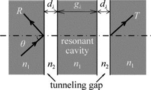
  • 共振光隧穿效应(ROTE)是在光学隧穿效应[12](受抑全内反射)的基础上提出来的一种新型的光学现象。光学隧穿效应是指光线从高折射率层照射到低折射率层,并且入射角大于临界角时,在界面处会发生全反射,当低折射率层的厚度足够小(小于入射光波长)时,光线将穿过低折射率层,即穿过经典几何光学中光线不能穿过的“壁垒”,形成透射(隧穿光线)。而共振光隧穿效应是在满足光学隧穿效应的前提下,促使隧穿光线在微米级的谐振腔中形成共振的一种光学效应[13-14]

  • 基于ROTE的加速度传感器结构如图 1所示。包括中间的圆柱形质量块和两根弹性悬臂梁与外边框相连。传感元件采用ROTE结构,如图 2所示。包含在中间的圆形质量块中。通过仿真分析,圆柱形质量块的半径设为0.775mm,其高度定为0.1mm,并根据仿真结果设计悬臂梁和外边框的几何尺寸。另外,关于传感元件ROTE结构的模型参量如表 1所示。表 1中, dλgλ均被量化为入射光中心波长的倍数。

    Figure 1.  a—diagram of acceleration sensor b—physical model diagram

    Figure 2.  Model of ROTE

    parameters symbols values
    s polarizer p polarizer
    static incident angle θ 22.5884° 22.5884°
    tunneling gap dλ 1.4700 1.4700
    width of resonant cavity gλ 10.0023 10.0790
    refractive index of input and output space n1 3.420 3.420
    refractive index of resonant cavity n1 3.420 3.420
    refractive index of tunneling gap n2 1.000 1.000

    Table 1.  Parameters of ROTE model[14]

    该加速度计可以通过标准硅微加工技术集成在硅片上,利用深反应离子刻蚀技术[15]可以使传感器每一部分的尺寸达到相对高的精度。并且通过热氧化法[16]、激光改进技术[17]、氢退火技术[18]等方法可以降低质量块的外表面和隧穿层的侧壁粗糙度。通过以上分析,确定了加速度计器件设计的可行性。

2.   传感器检测分析
  • 根据仿真结果,宽谱光源与水平方向的夹角设定为β=105°。当一个垂直的面内加速度作用到传感器上时,惯性力会促使中心质量块相对于外边框产生一个向上或向下的位移量,如图 3所示。以图 3a为例,入射光在质量块外表面发生折射后,将在输入层和第1层隧穿层的分界面产生初始入射角α0。当受到朝上的加速度作用时,中心质量块会产生向上的位移ΔH,由于光源位置不变,所以入射角由α0变为α1。同理,当加速度方向向下时,中心质量块会产生向下的位移ΔH,入射角由α1变为α0。由几何关系得到位移量ΔH与入射角(包括α0, α1)满足以下关系式:

    Figure 3.  Change of displacement ΔH in the state of perpendicular vibration

    式中,R(775μm)为圆形质量块的半径,γ0γ1均是入射光经过圆形块外表面时的法线与水平x轴的夹角。由此可以发现,当质量块产生面内的位移量时,入射光在质量块的外表面发生折射后,进入到质量块中的光透射强度T也会发生改变,以此可以实现加速度传感。

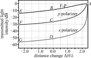
    图 4描述的是不同偏振态下透射光强度与中心质量块相对位移的关系。图中C点和D点分别对应s偏振和p偏振下的初始透射光强度。比较两曲线容易发现,s偏振光的陡峭程度要比p偏振光大得多,即s偏振光对于位移变化更加敏感,因此,该传感器在s偏振光的条件下将会有更优秀的表现。另外,法布里-珀罗(Fabry-Pérot,F-P)谐振腔作为经典的光学模型,其随位移变化的透射曲线也被绘制在图 4中。其中棱镜反射率设为95%,入射角设为3.335°,根据表 1中的参量,F-P谐振腔的腔长设置为12.94λ (λ为入射光的中心波长),基本等于ROTE模型的有效腔长。相比较而言,基于ROTE的传感器具有更高的灵敏度。另外,F-P谐振腔已经被证实具有小于5nm的位移分辨率[19],所以基于ROTE的s偏振光加速度计有望实现更高精度的测量。

    Figure 4.  Relationship between transmittance light intensity and displacement

3.   加速度计的COMSOL仿真分析
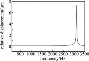
  • 持续的周期性载荷会使加速度传感器产生持续的周期响应,即谐响应。谐响应分析能够得到模型结构在不同载荷频率下的受力情况,由此可以确定传感器的工作带宽,避免共振损坏。实验中通过有限元法的COMSOL软件仿真完成对加速度传感器的谐响应分析。首先对结构添加边界约束条件并进行网格化,设定传感器工作方向的加速度值为1g(g=10m/s2),扫描频率为100Hz~3500Hz,得到的谐响应曲线如图 5所示。在频率3100Hz附近出现了谐振峰,扫描频率在3000Hz以下,谐响应曲线较为平坦,说明此频率范围可以避免共振损坏,因此100Hz~3000Hz可以作为加速度计的工作带宽。

    Figure 5.  Relationship between relative displacement and frequency

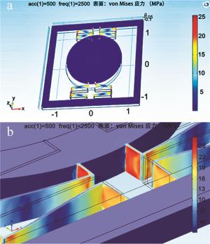
  • 弹性悬臂梁在加速度负载下会发生形变,超过弹性限度会导致加速度计的损坏。为了确保加速度计能够反复使用和测量的精确度,对加速度计进行了量程范围内的受力分析。设定工作频率为3000Hz,加速度取为500m/s2,其应力分布如图 6所示(图 6a中,xyz轴数值单位均为mm)。高应力值的区域主要有梁的拐角处、梁和内部质量块及外部方向框架的接触面位置,应力值最高为26MPa,远远小于极限应力值80MPa(以硅材料为例),无撞梁的情况发生,满足了加速度传感器设计的要求。

    Figure 6.  a—stress distribution in range b—close-up of details

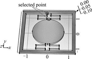
  • 为了测量加速度与位移的关系,选取了模型中合适的点进行分析,如图 7所示(图中数值单位均为mm)。圆圈部分即为所选点位,一点位于外部方形框架上,一点位于中心质量块边缘位置,可以得出两条加速度与位移变化的曲线,来消除因加速度计本身的位移变化而引起的误差。

    Figure 7.  Diagram of performance analysis point

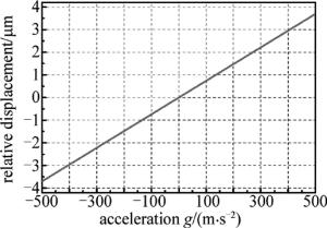
    所得的加速度与位移的关系如图 8所示。*点连线为中心质量块的位移变化,●点连线为外部框架的位移变化。可以看出两者的变化情况,最大变化分别为5.7μm与2μm。由于激光和探测器都固定在外部框架上,所以中心质量块相对光源产生的位移如图 9所示。从图中可以看出,在处于最大的加速度500m/s2情况下,中心质量块出现了3.74159μm的位移变化,此时结合之前给出的偏振光透光度曲线与位移的变化,可以求出加速度与偏振光传输曲线的变化。

    Figure 8.  Relationship between displacement and acceleration

    Figure 9.  Relationship between relative displacement and acceleration

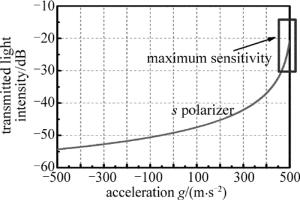
  • 设计中采用的是红外激光,波长为1.55μm,结合之前s型偏振光的数据与加速度与位移的数据可以得出最终结果。图 10是加速度与s型偏振红外激光透光度的曲线示意图以及部分数据对比。明显可以看出,在左半段曲线较为平缓,在右半段则非常陡峭,根据透光度的变化可以计算出加速度的变化。另外,曲线斜率最大的部分对应传感器的最大灵敏度。选取图 10中曲线陡峭的部分(用小框标出),计算得到其最大灵敏度为6.7dB/g(g=10m/s2)。

    Figure 10.  Relationship between transmittance T and acceleration

4.   ROTE原理验证实验
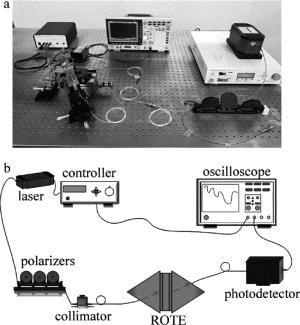
  • 根据仿真参量搭建ROTE实验模型,利用两个棱镜分别作为ROTE的输入、输出层,在两个棱镜的内表面各粘贴一层K9玻璃片作为ROTE的隧穿层,两个隧穿层之间注入折射率匹配液,作为ROTE的谐振腔。搭建实验测试平台,如图 11所示。实验中采用波长为1520nm~1570nm的红外激光器作为入射光源,依次经过准直器、偏振片、衰减器、ROTE结构、光电探测器和示波器。

    Figure 11.  Experimental test platform

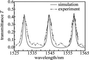
    根据仿真结果设置模型参量,通过示波器可以得到ROTE的透射谱线,如图 12所示。实线是仿真结果,虚线来源于实验测量。比较发现,两条曲线都表现出较高的品质因子,具有相同的自由谱宽度,吻合度较高, 验证了共振光隧穿效应的原理。

    Figure 12.  Relationship between transmittance and wavelength of ROTE in simulation and experiment

5.   结论
  • 通过对ROTE结构的加速度计的模型设计、结构参量分析,以及微线加速度计性能分析、灵敏度仿真、谐响应分析、基于频谱的位移检测分析等,设计了一种基于ROTE结构的线性加速度传感器。结果表明,基于ROTE结构的加速传感器在100Hz~3000Hz范围内、加速度为500m/s2的情况下,灵敏度可达到6.7dB/g,综合性能可与其它类型加速度传感器相媲美。该加速度传感器结构新颖、小巧简单,其设计思路为光学传感器的研究提供了新的方向,具有潜在的应用价值。

Reference (19)

Catalog

    /

    DownLoad:  Full-Size Img  PowerPoint
    Return
    Return