Advanced Search

ISSN1001-3806 CN51-1125/TN Map

Volume 42 Issue 5
Sep.  2018
Article Contents
Turn off MathJax

Citation:

Research of indoor positioning and illuminating systems based on visible light

  • Corresponding author: ZHAO Li, pilly_lily@126.com
  • Received Date: 2017-11-08
    Accepted Date: 2017-12-08
  • In order to solve the problem of low precision of indoor location algorithm, a set of visible light indoor positioning device which has illuminating function at the same time was designed. First of all, the layout of the indoor light source was arranged according to international standard of illumination. Secondly, a visible light transceiver system of intensity modulation/direct modulation (IM/DM) and an indoor positioning system platform with STM32 as core processor were designed. Finally, the calibration of target coordinates and regions was realized by using the method of multi point calibration relative positioning. The results show that, under the conditions suitable for illumination, measurement error is less than 10cm. The measurement error of partial location area is 3cm or even 0cm. Error resolution is 0.1cm, and relative error is less than 10cm. The research provides a scheme for current indoor positioning technology.
  • 加载中
  • [1]

    WU N, WANG X D, HU Q Q, et al. High precision indoor visible light positioning method based on multi-LED[J].Journal of Electronics & Information Technology, 2015, 37(3):727-732(in Chinese).
    [2]

    QIN X, DAI H. Design and analysis of indoor positioning system based on LED light[J]. Journal of Hangzhou Dianzi University, 2017, 37(4):6-9(in Chinese).
    [3]

    DONG W J, WANG X D, WU N, et al. Implementation of indoor visible light positioning system based on LED intensity[J]. Optical Communication Technology, 2017, 41(3):12-15(in Chinese).
    [4]

    LIU R L. Research on indoor positioning technology in visible light communication[D]. Beijing: Beijing University of Posts and Telecommunications, 2013: 1-49(in Chinese).
    [5]

    CHEN X H. Simulation and experimental study on the location method of indoor visible multi-parameter location fingerprint library[D]. Nanjing: Nanjing University of Posts and Telecommunications, 2015: 1-71(in Chinese).
    [6]

    GAO Y L, SHI A C. Implementation of indoor precision positioning algorithm based on white light LED[J]. Semiconductor Optoelectronics, 2015, 36(1):141-144(in Chinese).
    [7]

    LU H, CUI W J, BAI B, et al. Visible light localization algorithm with multiple observations constraints[J]. Journal of Xidian University, 2017, 44(4):156-161(in Chinese).
    [8]

    SHEN R, ZHANG J. Indoor location method based on visible light communication[J]. Journal of Information Engineering University, 2014, 15(1):41-45(in Chinese).
    [9]

    PANT K, ARMSTRONG J. Indoor localization using white LEDs[J]. Electronics Letters, 2012, 48(4):228-230. doi: 10.1049/el.2011.3759
    [10]

    SHEN Ch H, BAI R L, LI X. Planar positioning compensation method of vision-guided assembly robot[J]. Laser Technology, 2017, 41(1):79-84(in Chinese).
    [11]

    SUN L H, ZHAO X Y, GAO L T, et al. Measurement of laser spot center position based on sub-pixel positioning technique[J].Laser Technology, 2017, 41(4):511-514(in Chinese).
    [12]

    ZENG M, GONG Ch, XU Zh Y. An improved visible light positioning system based on RSS[J].Journal of University of Science and Technology of China, 2017, 47(2):188-194.
    [13]

    HE Sh Y. Indoor visible light communication system of key technologies[D]. Harbin: Harbin Institute of Technology, 2013: 1-124(in Chinese).
    [14]

    GUAN W P, WEN Sh Sh, HU X X, et al. Research on visible light communication system based on dual modulation technology[J]. Optoelectronics·Laser, 2015, 26(11):2125-2132(in Chinese).
    [15]

    DING D Q, KE X Zh. Visible light communication and its key technologies[J]. Semiconductor Optoelectronics, 2006, 27(2):114-117(in Chinese).
    [16]

    YUAN Q. International commission on illumination lighting standards-indoor workplace lighting[J]. Lighting Engineering, 2002, 13(4):55-60(in Chinese).
    [17]

    GAO Q, YU Y X, YU Zh Zh, et al. An indoor visible difference correction positioning algorithm based on RSS[J]. Semiconductor Optoelectronics, 2016, 37(4):536-539(in Chinese).
    [18]

    LU H B, LIANG J Q.Channel model of visible light indoor positioning system and its simulation analysis[J]. Chinese Journal of Optical Instrument, 2017, 39(2):64-69(in Chinese).
    [19]

    ZHOU Zh Sh. Based on convex optimization indoor visible light communication lamp arrangement[D].Nanjing: Nanjing University of Posts and Telecommunications, 2016: 1-60(in Chinese).
    [20]

    CHEN H Y, LIU W, LI L. Effects of relative phase noise on performance of coherent optical communication system[J]. Laser Technology, 2016, 40(1):94-98(in Chinese).
    [21]

    HU J B, LI M P. Design of novel tunable semiconductor laser in optical communication system[J]. Laser Technology, 2016, 40(2):280-283(in Chinese).
    [22]

    HUANG Zh H, WANG Y L, LI G F, et al. Adaptive frequency domain equalization algorithm in less-mode optical fiber communication system[J]. Laser Technology, 2017, 41(1):124-128(in Chinese).
  • 加载中
通讯作者: 陈斌, bchen63@163.com
  • 1. 

    沈阳化工大学材料科学与工程学院 沈阳 110142

  1. 本站搜索
  2. 百度学术搜索
  3. 万方数据库搜索
  4. CNKI搜索

Figures(6) / Tables(3)

Article views(6126) PDF downloads(189) Cited by()

Proportional views

Research of indoor positioning and illuminating systems based on visible light

    Corresponding author: ZHAO Li, pilly_lily@126.com
  • School of Electronic Information Engineering, Xi'an Technological University, Xi'an 710021, China

Abstract: In order to solve the problem of low precision of indoor location algorithm, a set of visible light indoor positioning device which has illuminating function at the same time was designed. First of all, the layout of the indoor light source was arranged according to international standard of illumination. Secondly, a visible light transceiver system of intensity modulation/direct modulation (IM/DM) and an indoor positioning system platform with STM32 as core processor were designed. Finally, the calibration of target coordinates and regions was realized by using the method of multi point calibration relative positioning. The results show that, under the conditions suitable for illumination, measurement error is less than 10cm. The measurement error of partial location area is 3cm or even 0cm. Error resolution is 0.1cm, and relative error is less than 10cm. The research provides a scheme for current indoor positioning technology.

引言
  • 随着无线网络、移动通信技术的快速发展以及基于信息感知的分布式网络的普及,建立在诸多新兴技术如广域泛在网络、人工智能、认知无线电及LTE Release 9+等基础上的定位技术引起了学者的极大研究兴趣,因此催生了许多应用广泛的基于位置的服务[1-3]。室外定位可借助全球定位系统(global positio-ning system, GPS)、伽利略导航和北斗定位[4-5],但对于室内定位,由于受障碍物、建筑物、通信链路以及多径效应的影响,其定位精度下降严重,不能满足人们日趋增长的室内精确定位需求[6]

    所谓室内定位, 即根据特定空间中已知的一系列参考点的位置坐标以及与位置相关的数据信息来获得该空间内移动终端设备或其持有者位置的过程[7-9],尽管用于室内定位的红外线定位、超声波定位、蓝牙定位、射频识别(radio frequency identification, RFID)定位、超宽带(ultra wideband, UWB)定位[10-11]、无线保真技术(wireless fidelity, WIFI)定位、Zigbee定位、麦克风阵列定位、即时定位与地图构建(simultaneous localization and mapping, SLAM)室内定位、室内电力线定位等技术可以提供从几米到几十厘米的定位精度,然而,大多数基于无线通信的系统会受到电磁干扰影响,在接入用户较多的情况下会导致定位质量的下降,并且其定位成本高,安全性也得不到有效保障[12]

    可见光通信是指利用室内照明发光二极管(light emitting diode, LED)实现无线通信的新技术,由于其具有无电磁干扰、保密性好、易部署等优点,基于可见光的室内定位技术应运而生,成为未来一个发展趋势[13-15]。作者以80cm×80cm×80cm的室内空间为研究平台,兼顾照明与定位,设计了满足国际标准的光源布局模型,并提出了多点标定相对定位算法,实现了基于可见光的精确室内定位,为室内定位提供了一种有效的解决方案。

1.   可见光定位系统建模
  • 本文中设计了一种基于可见光的室内定位系统,系统模型如图 1所示。图中PD为光电二极管(ptotodiode), 本系统以3个LED灯珠为光源,在发送端将需要传送的信息通过调制电路加载到驱动LED光源的电流上,以LED光源作为信息传输的载体;在接收端光电检测器作为光信号测量电路的信息采集与接收器,由光敏电阻及其控制电路组成,将接收到的数据通过STM32F103进行数据处理,所获数据经STC15F2K60S2单片机将定位坐标输出到LCD显示屏上。通过数据标定整合实现了对可见光光强采集、室内定位及数据显示。

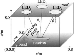
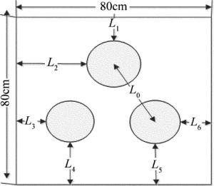
  • 图 2为本文中搭建的室内光源布局模型。房间大小为80cm×80cm×80cm的正方体,采用3个5W的LED灯珠作为光源,定位目标点为地面平面,以房间一角作为坐标原点建立3维坐标系。根据国际照明标准规定[16],办公室内的光照度必须保持在300lx~1500lx之间,为了保证照度要求,需对3颗灯珠的布局进行合理设计。图 3为LED灯珠在天花板上的分布示意图。3颗灯珠在天花板上呈等边三角形分布,边长L0=2cm, 各灯珠距离房顶边缘的距离分别为:L1=40.86cm,L2=40cm,L3=L6=39cm,L4=L5=39.13cm。单颗LED灯珠在接收平面某点的照度可表示为[17-18]

    Figure 2.  Layout model of indoor light source

    Figure 3.  Layout of LED array on the ceiling

    式中, I0为LED的中心发光强度,m为光源的辐射模式,ϕ为光源的发射角,ψ为定位点的入射角,dn为光源到定位点的距离。假设点光源的坐标为(xn, yn, 0.8), 在地面接收面上某一点坐标为(x, y, 0),则dn可表示为[19-20]

    由于cosϕ=cosψ=0.8/dn, 所以En可简化为:

    由于LED发出的光为非相干光,则接收平面上某点接收到的总的光照度为[21-22]

    式中, En为各个点光源在到达接收面某点(xy,0)时接收到的光照度,M为总的光源个数。

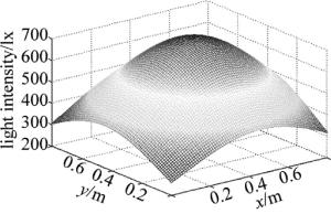
    根据以上布局,光源选择呈等边三角形分布的3个LED灯珠,则接收平面的光照度分布如图 4所示。光照度值都在300lx~1500lx之内,满足国际规定的照度标准。

    Figure 4.  Distribution map of light intensity

2.   多点标定相对定位原理
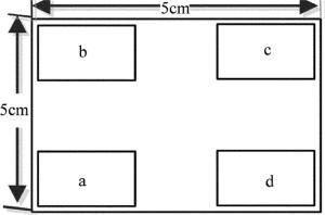
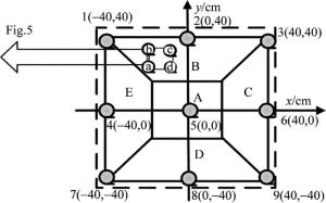
  • 本系统所设计的定位传感器模型如图 5所示。作为接收LED光源所发出的信号,其作用为光电检测器。由于光敏电阻对光的敏感度高、感光性好,为保证定位准确及定位的便捷性和电路稳定性,因此用光敏电阻代替光电检测器,作为测量电路的定位装置。在图 5的定位装置中, a, b, c, d分别为4个光敏电阻, 均匀地分布在5cm×5cm的电路板4个顶点处。

    Figure 5.  Model of sensor

    由于本系统采用的是呈等边三角形分布的LED光源布局方式, 在接收端可保证传感器能接收到3个互不干扰的信号,对于接收到的光照信号采取多点标定光强相对定位法进行处理。

    根据接收平面光照度不同对目标平面进行区域划分及坐标点定位, 如图 6所示。目标平面为室内地面,首先将地面进行坐标化、区域化,以地面正中心为坐标原点建立平面直角坐标系,坐标原点即房间正中心点,将整个地面划分为A, B, C, D, E这5个区域,其中A区域为边长40cm的正方形。其次对其中9个特殊中心点边界坐标定位,其标号为1~9,具体坐标已给出。

    Figure 6.  Map of ground coordinate

    对传感器4个顶点采集到的光照强度进行相应的数据处理,将4个光敏电阻所接收到的光照强度转换为电压量化后的值, 可表示为:uaubucud,根据各点光照强度量化值即可判断定位目标点所在区域。

    由于相邻传感器接收电压量化值之差会随着传感器所处位置而变化,因此, 可根据不同点可见光的光照强度的差值判别目标点的坐标,实现传感器的相对定位,设相邻两个传感器电压量化值之差分别为:ubcuadubaucd,其差值可表示为:

    式中, ubcuad为水平方向相邻两个光敏电阻所获数据的差值,ubaucd为竖直方向两相邻光敏电阻所获数据的差值;令uh(i),uv(i)分别为任意目标点水平方向差值的均值与竖直方向差值的均值, 则有:

    经过光照度的数值计算,在定位中心点5处,相邻传感器所接收到的数据差值接近于0,因此以定位坐标点5作为中心参考点,根据目标位置处光照量化值与定位中心点处的差值及系统灵敏度以确定定位目标点的坐标。令A(i)为任意待定位点的uh(i)与中心处uh(5)的光照强度量化值的差值,B(i)为任意待定位点uv(i)与中心处uv(5)的光照强度量化值的差值,其中i为位置标号,则有:

    为了精确标定各个方向光照强度的变化率,本文中选定2, 4, 6, 8这4个特殊点,分别根据这4个点的光照强度及其距离中心点的距离,数值计算x轴两侧及y轴两侧的定位灵敏度WiPi, 则有:

    式中,d为4个特殊点到地面中心的距离,d=40cm。为方便计算,待定位点坐标引入坐标平面x轴与y轴方向平均灵敏度WxPy, 则有:

    xxyy为目标定位点的所测坐标,则有:

    e为相对误差, 则有:

    式中, xy为目标定位点的实际坐标。

3.   系统实现及结果
  • 在该套可见光定位系统当中,房间模型为80cm×80cm×80cm的正方体,采用强度调制/直接检测(intensity modulation/direct modulation, IM/DM)调制方式,光源为3个5W的LED灯珠呈等边三角形均匀分布在天花板正中心;信号接收端为4个光敏电阻组成的定位传感器阵列,以STM32处理器集成的高分辨率及强抗噪声的12位A/D作为数据处理部分,经过多次标定将所测定位坐标显示在LCD显示屏上。

    表 1为9个特殊中心及边界点位置对应的9组光照度量化数据及所在的室内地面区域。将表 1按照(5)式~(8)式的相对差值数据处理方法进行计算,所获数据及定位灵敏度如表 2所示。将表 2按照(10)式~(11)式进行坐标转换,计算得到定位点位置参量,将其与实际定位坐标进行对比,结果如表 3所示。

    position ua ub uc ud area
    1 691 478 772 1300
    2 1160 653 605 1062 B
    3 1087 659 291 626
    4 752 701 1145 1225 E
    5 1215 1165 1185 1251 A
    6 1221 1162 707 771 C
    7 470 700 1305 770
    8 831 1170 1324 786 D
    9 944 1144 901 413

    Table 1.  Quantitative and regional analysis of light intensity

    position ubc uad uba ucd uh(i) uv(i) A(i) B(i) Pi Wi
    1 294 609 213 528 451.5 370.5 423.5 312.5
    2 48 98 507 457 73 482 45 424 10.6
    3 368 461 428 335 414.5 381.5 386.5 323.5
    4 444 473 51 80 458.5 65.5 430.5 7.5 10.763
    5 20 36 50 66 28 58 0 0
    6 455 450 59 64 452.5 61.5 424.5 3.5 10.613
    7 605 300 230 535 452.5 382.5 424.5 324.5
    8 154 45 339 538 99.5 438.5 71.5 380.5 9.513
    9 243 531 200 488 387 344 359 286

    Table 2.  Light intensity difference and sensitivity analysis

    position x/cm y/cm xx/cm yy/cm Δx/cm Δy/cm e/cm
    1 -40 40 -42 31 2 9 9.21954446
    2 0 40 4 42 4 2 4.47213595
    3 40 40 38 32 2 8 8.24621125
    4 -40 0 -43 1 3 1 3.16227766
    5 0 0 2 5 2 5 5.38516481
    6 40 0 42 1 2 1 2.23606798
    7 -40 -40 -42 -32 2 8 8.24621125
    8 0 -40 7 -38 7 2 7.28010989
    9 40 -40 36 -28 4 12 12.6491106

    Table 3.  Comparison table of positioning error

    实验数据表明,除第9个目标点外,其它8个目标定位点实测位置与实际位置的误差值Δx,Δy在10cm以内,相对误差e的值均小于10cm,LCD显示分辨率为0.1cm,定位误差达到厘米级标准; 由于目标位置9靠近室内门外受自然光影响较大,导致定位误差较大,说明本文中提供的算法对某些特殊点仍需改进。

4.   结论
  • 研究并设计了一套兼顾照明与定位的可见光室内定位系统。将室内定位的光源进行了布局,使其满足国际照明标准;设计了整个定位系统的硬件平台,采用合理的定位算法对数据进行融合处理,并且计算了定位灵敏度与相对误差,实现了对可见光光强采集、室内定位及数据显示。经过最终的级联和调试,本系统坐标实际测量误差低于10cm, 显示分辨率为0.1cm, 供电功率低于5W,LCD数据显示定位误差满足厘米级的高精度定位。实验系统证明了该方法的可行性,可以满足目前室内定位的需求,为室内目标定位提供了一种可靠有效的解决方案。

Reference (22)

Catalog

    /

    DownLoad:  Full-Size Img  PowerPoint
    Return
    Return