Advanced Search

ISSN1001-3806 CN51-1125/TN Map

Volume 42 Issue 4
May  2018
Article Contents
Turn off MathJax

Citation:

Comparative experimental research of molten liquid ejection from soild targets induced by millsecond pulse laser

  • Corresponding author: NI Xiaowu, nxwhome@njust.edu.cn
  • Received Date: 2017-11-21
    Accepted Date: 2017-12-08
  • In order to study molten liquid ejection mechanism induced by interaction between millisecond laser and silicon targets, based on the so-called shadow method, the process of molten liquid ejection was studied after the sequence shading pictures of the interaction between the millisecond laser and the solid targets (silicon and aluminum) were recorded by high speed CCD. The difference between melting and splashing process of silicon and aluminum targets caused by millisecond laser was compared. The mechanism of solid melting splashing formed by millisecond laser was also discussed. According to the different melting and splashing mechanism of the two targets, the reasons of splashing angle, splash distribution and splash brightness of two targets were explained. The results show that, millisecond laser can produce gasification and melting spatter process for both targets, but gasification intensity, shape and brightness of the melted splash are different. When interacting with silicon targets, the gasification phenomenon is not obvious in the action area. The molten splash is liquid drop. Its brightness is stronger than the background. The maximum angle between the splashing direction and the normal line of the front target surface is 45°, and the molten spatter is distributed within the angle. When interacting with aluminum targets, gasification phenomenon is more obvious in the action area. The molten splash is linear opaque fluid. Its brightness is lower than the background light. The angle between the splashing direction and the normal line of the front target surface is 20°. The molten spatter is distributed along the line of splashing direction. The study is helpful for laser processing technology.
  • 加载中
  • [1]

    LIU Q B. Laser processing technology and its application[M]. Beijing:Metallurgical Industry Press, 2007:4-6(in Chinese).
    [2]

    ZANG Y N, NI X W, HAN B. The ejection of molten aluminum after the interaction with millisecond pulsed laser[J]. Journal of Optics, 2017, 46(3):231-240. doi: 10.1007/s12596-017-0402-5
    [3]

    WEI Z, ZHANG W, WANG D, et al. Structural, optical and electrical behavior of millisecond pulse laser damaged silicon-based positive intrinsic negative photodiode[J]. Optik-International Journal for Light and Electron Optics, 2017, 131(sC):110-115.
    [4]

    JIA Zh X, HUANG J G, GAO J Q, et al. Technological study on long pulse laser cutting of polycrystalline cubic boron nitride[J]. Laser Technology, 2017, 41(3):346-350(in Chinese).
    [5]

    SCHNEIDER M, BERTHE L, FABBRO R, et al. Gas investigation for laser drilling[J]. Journal of Laser Applications, 2007, 19(3):165-169. doi: 10.2351/1.2567844
    [6]

    ZANG Y N, NI X W, HAN B. The ejection threshold of molten aluminum induced by millisecond pulsed laser[J]. Journal of Applied Physics, 2014, 116(1):013104. doi: 10.1063/1.4887073
    [7]

    HE X L, DEBROY T, FUERSCHBACH P W. Alloying element vaporization during laser spot welding of stainless steel[J]. Journal of Physics, 2003, D36(23):3079-3088.
    [8]

    HE X L, NORRIS J, FUERSCHBACH P, et al. Liquid metal expulsion during laser spot welding of 304 stainless steel[J]. Journal of Physics, 2006, D39(3):525-534.
    [9]

    SEMAK V, MATSUNAWA A. The role of recoil pressure in energy balance during laser materials processing[J]. Journal of Physics, 1997, D30(18):2541-2552.
    [10]

    KELLY R, MIOTELLO A. Comments on explosive mechanisms of laser sputtering[J]. Applied Surface Science, 1996, 96:205-215.
    [11]

    CHO J H, NA S J. Implementation of real time multiple reflection and Fresnel absorption of laser beam in keyhole[J]. Journal of Physics, 2006, D39(24):5372-5378.
    [12]

    ZHANG Y M, SHEN Zh H, NI X W. Modeling and simulation on long pulse laser drilling processing[J]. International Journal of Heat and Mass Transfer, 2014, 73:429-437. doi: 10.1016/j.ijheatmasstransfer.2014.02.037
    [13]

    LU Q M, MAO S S, MAO X L, et al. Theory analysis of wavelength dependence of laser-induced phase explosion of silicon[J]. Journal of Applied Physics, 2008, 104(8):083301. doi: 10.1063/1.2978369
    [14]

    LU Zh Q. Two-phase flow and boiling heat transfer[M]. Beijing:Tsinghua University Press, 2002:146-158(in Chinese).
    [15]

    XU J Y, JIA D N. The boiling heat transfer and gas-liquid two phase flow[M]. Beijing:Atomic Energy Press, 2001:201-233(in Chinese).
    [16]

    TAKASUKA E, TOKIZAKI E, TERASHIMA K, et al. Emissivity of liquid silicon in visible and infrared regions[J]. Journal of Applied Physics, 1997, 81(9):6384-6384. doi: 10.1063/1.364418
    [17]

    HIRANO K, FABBRO R, MULLER M. Experimental determination of temperature threshold for melt surface deformation during laser interaction on iron at atmospheric pressure[J]. Journal of Physics, 2011, D44(43):435402.
    [18]

    MOSTOVYCH A N, CHAN Y. Reflective probing of the electrical conductivity of hot aluminum in the solid, liquid, and plasma phases[J]. Physical Review Letters, 1997, 79(25):5094-5097. doi: 10.1103/PhysRevLett.79.5094
  • 加载中
通讯作者: 陈斌, bchen63@163.com
  • 1. 

    沈阳化工大学材料科学与工程学院 沈阳 110142

  1. 本站搜索
  2. 百度学术搜索
  3. 万方数据库搜索
  4. CNKI搜索

Figures(3)

Article views(6099) PDF downloads(160) Cited by()

Proportional views

Comparative experimental research of molten liquid ejection from soild targets induced by millsecond pulse laser

    Corresponding author: NI Xiaowu, nxwhome@njust.edu.cn
  • School of Science, Nanjing University of Science and Technology, Nanjing 210094, China

Abstract: In order to study molten liquid ejection mechanism induced by interaction between millisecond laser and silicon targets, based on the so-called shadow method, the process of molten liquid ejection was studied after the sequence shading pictures of the interaction between the millisecond laser and the solid targets (silicon and aluminum) were recorded by high speed CCD. The difference between melting and splashing process of silicon and aluminum targets caused by millisecond laser was compared. The mechanism of solid melting splashing formed by millisecond laser was also discussed. According to the different melting and splashing mechanism of the two targets, the reasons of splashing angle, splash distribution and splash brightness of two targets were explained. The results show that, millisecond laser can produce gasification and melting spatter process for both targets, but gasification intensity, shape and brightness of the melted splash are different. When interacting with silicon targets, the gasification phenomenon is not obvious in the action area. The molten splash is liquid drop. Its brightness is stronger than the background. The maximum angle between the splashing direction and the normal line of the front target surface is 45°, and the molten spatter is distributed within the angle. When interacting with aluminum targets, gasification phenomenon is more obvious in the action area. The molten splash is linear opaque fluid. Its brightness is lower than the background light. The angle between the splashing direction and the normal line of the front target surface is 20°. The molten spatter is distributed along the line of splashing direction. The study is helpful for laser processing technology.

引言
  • 激光加工具有非接触、效率高、易控制等特点[1],因而在工业生产中有着重要的应用,已经被广泛应用到金属[2]、半导体[3]、复合材料[4]等领域。在利用脉冲激光打孔过程中,主要涉及熔融、气化以及熔融喷溅等现象[5]。在毫秒激光和金属靶材相互作用过程中,当材料表面出现气化以后,物质蒸气产生的气化压力使得熔融液体从材料表面向外喷溅[6]。2003年,HE等人[7]报道了脉宽为3ms、能量密度仅为392J/cm2的毫秒激光与304#不锈钢的相互作用,发现钢靶表面最高温度可达3052K,超过了304#不锈钢的沸点(2980K); 2006年,他们继续对304#不锈钢熔融喷溅的产生条件进行研究,结果表明,当材料表面温度大于沸点约100K~200K时,将会有液态喷溅物出现[8]。SEMAK等人结合能量守恒定律,数值模拟了铁靶和铝靶的表面温度、气化速度、熔融喷溅速度等随入射激光功率密度的变化规律[9]。然而,上述熔融喷溅过程的研究均是基于毫秒激光与金属靶材的相互作用,而毫秒激光与硅靶相互作用产生的熔融喷溅的机理及其与金属靶差异尚未见报道。

    作者通过阴影法研究了毫秒激光致硅靶和铝靶产生的熔融喷溅过程,得到了脉宽为1ms,能量为7.38J和16.00J的Nd3+: YAG高斯激光与厚0.3mm硅靶和厚4.0mm铝板相互作用中产生熔融喷溅过程的阴影图。通过序列阴影图的对比,发现毫秒激光对两种靶材均能产生气化和熔融喷溅过程,但熔喷喷溅物形态、亮度、分布区域以及熔融喷溅的角度均不相同,进而根据毫秒激光致硅靶和铝靶融熔喷溅产生的机理分析了其产生熔融喷溅现象和机理的异同。

1.   实验系统
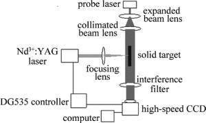
  • 实验装置可分为毫秒激光与靶材相互作用光路和探测光路两部分,如图 1所示。毫秒激光与靶材相互作用光路为高能毫秒激光束经过聚焦透镜辐照在靶材上,聚焦透镜的焦距为152mm,靶材表面的光束半径为0.2mm。实验中铝靶厚度为4mm,硅靶厚度为0.3mm, Nd3+: YAG毫秒激光器型号为Beamtech Melar 50,输出波长为1064nm,脉宽为0.5ms~2.5ms可调,激光能量调节范围为0J~50J。实验中,采用的激光脉宽为1ms,单脉冲激光能量分别选取7.38J和16.00J。探测光路中的探测激光的波长为532nm,功率为500mW。探测激光束经过扩束透镜、准直透镜、靶材以及带通干涉滤光片后,并由Southern Vision System公司的Gigaview高速CCD记录整个相互作用过程,最后由计算机存储图像。经过扩束镜和准直透镜后的激光束光斑半径为2cm。Gigaview高速CCD在分辨率为1280×1280时,拍摄帧率为4261frame/s。532nm的带通干涉滤光片的半带宽为30nm。实验中使用DG535控制器调节毫秒高能激光器与高速CCD进行同步触发,触发精度为0.15ns。

    Figure 1.  Experimental apparatus

2.   实验结果
  • 毫秒激光致硅靶和铝靶的熔融喷溅过程的序列阴影图对比情况如图 2所示。图 2中左侧为毫秒激光致硅靶熔融喷溅过程序列阴影图,右侧为毫秒激光致铝靶熔融喷溅过程序列阴影图。在实验中,脉冲为1ms、能量为7.38J的毫秒激光从左至右辐照在靶材上,其中硅靶的厚度为0.3mm,而铝靶的厚度为4mm。在图 2左侧的序列阴影图中,当激光作用233μs时,激光作用区域中熔融硅的亮度高于背景光(背景光为探测激光束);当激光作用466μs时,硅靶前表面和后表面均出现了熔融喷溅物;当激光作用699μs时,硅靶前表面和后表面出现了更多的熔融喷溅物;当激光作用932μs时,可见硅靶前表面和后表面熔融喷溅物逐渐分散开,呈现液滴状,硅靶产生的熔融喷溅方向与靶材前表面法线的最大夹角约为45°,熔融喷溅物分布于两最大喷溅角之间,且硅靶前后表面熔融喷溅物的喷溅方向相反。在整个毫秒激光与硅靶相互作用过程中,熔融喷溅物的亮度总是高于背景光。在图 2右侧的序列阴影图中,当激光作用233μs时,激光作用区域中熔融铝的亮度低于背景光,铝靶前表面出现了气化喷溅物,并且气化喷溅物的亮度高于背景光;当激光作用466μs时,可见气化喷溅物在空气中传播,气化喷溅物的喷溅方向与激光入射方向相反;在激光作用1165μs时,可见气化喷溅物逐渐消散。在整个毫秒激光与铝靶相互作用过程中,气化喷溅物的亮度高于背景光,并且直接观测到气化喷溅物产生、传播和逐渐消失的过程。
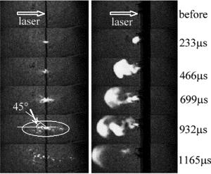
    Figure 2.  Sequence shadow pictures about the process of molten liquid ejection produced by millsecond laser interaction with silicon and aluminum targets

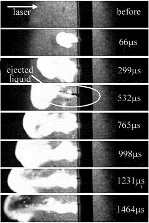
    在上述实验中,值得注意的是铝靶产生的熔融喷溅现象并不十分明显。为了得到激光作用铝靶的熔融喷溅过程,加大毫秒激光能量至16.0J,得到的序列阴影图如图 3所示。在图中,脉冲为1ms、能量为16.0J的毫秒激光从左至右照射到厚度为4mm的铝靶表面上。从序列阴影图可以看出,当激光作用66μs时,铝靶表面出现了气化的物质蒸气,并且物质蒸气的亮度明显高于背景光的亮度;当激光作用299μs时,物质蒸气在空气中逐渐扩大,并且铝板表面出现了熔融喷溅物;当激光作用532μs时,铝靶表面出现了更多的熔融喷溅物,但在靶材表面产生的物质蒸气却减少了。铝靶产生的熔融喷溅方向与靶材前表面法线的夹角大约为20°,熔融喷溅物在空间呈线状分布在喷射角所在的直线上。铝靶表面熔融喷溅方向与激光入射方向相反;当激光作用765μs时,铝靶表面又产生了物质蒸气和熔融喷溅物;当激光作用超过1ms后,物质蒸气逐渐消失。在熔融喷溅过程中,熔融喷溅物为线状、不透明的液体,其亮度低于背景光。

    Figure 3.  Sequence shadow pictures about the process of molten liquid ejection produced by millsecond laser interaction with aluminum targets

3.   分析和讨论
  • 起初在硅靶前表面和后表面均产生了熔融喷溅物,由于熔融喷溅物速度不同而逐渐分离开,最后可观测到熔融喷溅物呈现液滴状;而铝靶产生的熔融喷溅物呈线状不透明流体,并且由于喷溅速度的不同而逐渐分离开。

    在激光与靶材相互作用产生的熔融喷溅过程研究中,其可能产生熔融喷溅的机理有两种:(1)根据流体动力学,物质蒸气产生的气化压力使得熔融液体从材料表面向外喷溅[8];(2)根据热物理学理论,液-气相变过程中的过热沸腾同样可使得熔融液体从材料表面向外喷溅[10]。对于毫秒激光与铝靶相互作用,其熔融喷溅的机理应用流体力学理论[6, 11-12];而对于毫秒激光与硅靶相互作用的熔融喷溅机理未见报道,由于硅靶和铝靶的熔融喷溅现象存在诸多不同,因此考虑毫秒激光致硅靶产生过热沸腾现象。过热沸腾即体积气化,它的气化机制与面气化机制不同,主要是小气泡在过热液体中成核、长大、最后导致沸腾现象出现[13]。超过沸点的熔融硅液体内部形成小气泡,并且当小气泡膨胀至一定大小时带着周围的熔融液体离开硅靶表面,因此,在熔融喷溅过程中,熔融喷溅物呈现液滴状。而铝靶形成熔融喷溅的机理为物质蒸气产生的气化压力使得熔融液体从材料表面向外喷溅,在外力的作用下液体向离开靶材的方向移动,因此呈现线状分布。

  • 硅靶产生的熔融喷溅方向与靶材前表面法线所成夹角最大值为45°;而铝靶产生的熔融喷溅方向与靶材前表面法线的夹角较小,约为20°。对于硅靶而言,当熔融喷溅现象出现时,气泡自身产生的气化压力要大于外力,气泡必然向外力最小的方向运动[14]。在激光作用区域,硅靶的径向温度逐渐降低,而气化饱和蒸气压随温度的降低而减小[13],因而,在径向上气化饱和蒸气压强是逐渐减小的。在激光作用区域的边缘附近,在自身产生的气化压力、气化饱和蒸气压力和固-液交界面的共同限制下,融熔喷溅物以一定角度离开靶材。实验中,熔融喷溅的角度最大值大约为45°。而对于铝靶而言,其融熔喷溅方向主要是熔融液体受到外力的合力方向,这其中包括气化蒸汽压力、表面张力等作用力[6],在实验中,靶产生的熔融喷溅方向与靶材前表面法线的夹角大约为20°。

  • 硅靶产生熔融喷溅物分布在两个最大喷溅角之间,铝靶产生的熔融喷溅物在空间呈线状分布在喷溅方向所在的直线周围。对于硅靶而言,过热沸腾过程中产生的气泡是服从Boltzmann[15]分布的,在这种分布下,小气泡布满在激光作用区域,在自身产生的气化压力,周围气泡压力和硅靶表面饱和蒸汽压力的共同作用下形成液态喷溅。因此,在实验中看到融熔喷溅物分布在两个最大喷溅角之间。而对于铝靶而言,熔融液体受到合力的方向确定以后,其融熔喷溅方向也确定,因此,铝靶产生的熔融喷溅物在空间呈线状分布在喷溅方向所在的直线周围。

  • 硅靶产生熔融喷溅物的亮度高于背景光,而铝靶产生的熔融喷溅物亮度低于背景光。由于实验所用的高速CCD前放置了波长为532nm的带通干涉滤波片,因而高速CCD记录的主要是波长为532nm±15nm光波。在实验中,硅靶产生的融熔喷溅物的亮度高于背景光,因此高温融熔液体硅存在热辐射现象。这里假设将发生过热沸腾现象,即融熔液体的温度要超过其沸点,而硅的沸点温度为3514K,在计算中假定熔融喷溅物的温度为3500K,根据黑体辐射辐射强度的定义和液态硅的发射率ε=0.27[16],温度为3500K的液态硅在带通干涉滤光片透光波段517nm~547nm的辐射强度为:

    式中,λ是波长,Eb表示黑体辐射强度。实验中使用波长为532nm的连续激光器,输出功率500mW,半径为2cm,对应背景光辐射强度为:

    由以上计算结果可见,液态硅在517nm~547nm波段的辐射强度约为背景光源的78.7(M=E/Ib=78.7)倍。可见,高温液态硅辐射光强度远高于背景光,由此可推知在毫秒激光作用下硅的熔融液体温度高于其沸点温度。而对于铝靶而言,毫秒激光的能量密度大于铝靶的熔融喷溅阈值[6],整个熔融层的液体在气化压力的作用下离开铝靶表面。由于发射率和吸收率近似相等[17],而液态铝对波长532nm的吸收率为0.25[18]。根据黑体辐射辐射强度的定义和背景光的强度,融熔液态铝辐射的光强度和背景光相等时,融熔铝的温度为2250K。铝靶的熔点为933K,温度为933K~2250K的融熔铝离开靶材时,其亮度低于背景光。因此,在实验中,观察到的熔融喷溅物的亮度低于背景光,即毫秒激光作用下铝的熔融液体温度低于其沸点温度。

4.   结论
  • 将脉宽为1ms的激光致硅靶和铝靶的熔融喷溅过程的阴影图进行对比,研究了硅靶和铝靶熔融喷溅过程。在研究过程中,将过热沸腾的机理引入到毫秒激光与硅靶相互作用过程中,进而根据毫秒激光致硅靶和铝靶融熔喷溅产生的机理分析硅靶和铝靶产生熔融喷溅现象的不同。

    (1) 2种靶材熔融喷溅物的形态不同。熔融液态硅内部形成气泡并膨胀直至离开硅靶表面,形成液滴状融熔喷溅物;而铝靶在外力的作用下液体离开靶材的方向移动,因此呈现线状分布。

    (2) 熔融喷溅夹角与和融熔喷溅物的分布不同。硅靶产生的气泡服从Boltzmann分布,气泡离开硅靶后形成融熔喷溅物分布在两个最大喷溅角之间,最大喷溅角约为45°;而铝靶融熔喷溅物的方向为所受外力的合力方向,因此融熔喷溅物分布在喷溅方向所在的直线周围,喷溅角度约为20°。

    (3) 熔融喷溅物的亮度不同。硅的融熔喷溅物是温度大于沸点的液体,高温融熔液态喷溅物可辐射可见光谱,因此其亮度高于背景光;而铝靶融熔喷溅物是温度大于熔点的液体,低温融熔液态铝是不能辐射可见光谱的,因此其亮度低于背景光。毫秒激光可应用于激光打孔,激光切割等。

    本文中的实验结果将对毫秒激光致固体靶材熔融喷溅的机理研究提供理论依据。

Reference (18)

Catalog

    /

    DownLoad:  Full-Size Img  PowerPoint
    Return
    Return