Advanced Search

ISSN1001-3806 CN51-1125/TN Map

Volume 42 Issue 3
Mar.  2018
Article Contents
Turn off MathJax

Citation:

Radio-over-fiber transmission based on ultra-long distributed 2-order Raman amplifier

  • Corresponding author: JIN Xiaofeng, jinxf00@zju.edu.cn
  • Received Date: 2017-08-11
    Accepted Date: 2017-09-20
  • In order to improve the link gain and transmission distance of radio-over-fiber (RoF) frequency transmission link, ultra-long distributed second-order Raman amplifier structure in L band was used to amplify the light signal. The principle of the distributed 2-order Raman amplifier and the RoF transmission link were explained theoretically. The relationships among them were analyzed by using the coupling equations between signal light, 1-order pumping light, 2-order pumping light and noise. The 1-order radio frequency (RF) signal gain of a RoF transmission system based on ultra-long distributed 2-order Raman amplifier was also obtained. Through numerical simulation and system experiment, the effect of pumping power on on-off gain of ultra-long distributed 2-order Raman amplifier, frequency response and RF gain of RoF transmission system in the range of 0GHz~7GHz, and phase noise of RoF transmission link after the application of ultra-long distributed 2-order Raman amplifier were obtained. The results show that the link gain of 28.1dB is obtained by RoF transmission after the application of an ultra-long distributed 2-order Raman amplifier. Approximate lossless transmission is achieved in optical link with a distance of 80.94km. The on-off gain of RF signal is independent of the frequency of RF signal. The study has important application value in long distance transmission of optical radio frequency links.
  • 加载中
  • [1]

    SEEDS A J, WILLIAMS K J. Microwave photonics[J]. Journal of Lightwave Technology, 2006, 24(12):4628-4641. doi: 10.1109/JLT.2006.885787
    [2]

    YAO J. Microwave photonics[J]. Journal of Lightwave Technology, 2009, 27(3):314-335. doi: 10.1109/JLT.2008.2009551
    [3]

    WAKE D, WEBSTER M, WIMPENNY G, et al. Radio over fiber for mobile communications[C]//2004 IEEE International Topical Meeting on Microwave Photonics. New York, USA: IEEE, 2004: 157-160.
    [4]

    SONG H J, LEE J S, SONG J I. All-optical frequency upconversion of radio over fibre signal with optical heterodyne detection[J]. Electronics Letters, 2004, 40(5):330-331. doi: 10.1049/el:20040219
    [5]

    NAJI A W, HAMIDA B A, CHENG X S, et al. Review of Erbium-doped fiber amplifier[J]. International Journal of Physical Sciences, 2011, 6(20):4674-4689.
    [6]

    BOUZID B. Analysis and review of erbium doped fiber amplifier[C]//2013 Saudi International Electronics, Communications and Photonics Conference.New York, USA: IEEE, 2013: 1-5.
    [7]

    LI Z, NIRMALATHAS A, BAKAUL M, et al. Performance of WDM fiber-radio network using distributed Raman amplifier[J]. IEEE Photonics Technology Letters, 2006, 18(4):553-555. doi: 10.1109/LPT.2005.863179
    [8]

    CHANDRA S, VARDHANAN A V, GANGOPADHYAY R. Simultaneous dispersion and non-linearity compensation with OPC-DRA combination for a mm-wave radio-over-fiber transmission system[C]//2006 IFIP International Conference on Wireless and Optical Communications Networks.New York, USA: IEEE, 2006: 5.
    [9]

    CHEN M L, QU P F, SUN L J, et al. Performance analysis in ultra-long-haul repeaterless microwave photonic link with Raman amplifier[J]. Optoelectronic Technology, 2014, 34(4):283-287(in Chinese).
    [10]

    SU B L. Investigation on quasi-lossless transmission system based on hybrid pumping Raman amplification[J]. Laser Technology, 2017, 41(2):265-269(in Chinese).
    [11]

    ANIA-CASTAÑÓN J D, TURITSYN S K. Noise and gain optimisation in bi-directionally pumped dispersion compensating amplifier modules[J]. Optics Communications, 2003, 224(1):107-111.
    [12]

    ANIA-CASTAÑÓN J D. Quasi-lossless transmission using second-order Raman amplification and fibre Bragg gratings[J]. Optics Express, 2004, 12(19):4372-4377. doi: 10.1364/OPEX.12.004372
    [13]

    ELLINGHAM T J, ANIA-CASTAÑÓN J D, IBBOTSON R, et al. Quasi-lossless optical links for broad-band transmission and data processing[J]. IEEE Photonics Technology Letters, 2006, 18(1):268-270. doi: 10.1109/LPT.2005.862001
    [14]

    ANIA-CASTAÑÓN J D, KARALEKAS V, HARPER P, et al. Simultaneous spatial and spectral transparency using ultra-long fibre laser transmission[C]//33rd European Conference and Exhibition of Optical Communication.Berlin, Germany: Verband der Elektrotechnik, 2007: 1-2.
    [15]

    KARALEKAS V, ANIA-CASTAÑÓN J D, HARPER P, et al. Ultra-long Raman fibre laser transmission links[C]//200911th International Conference on Transparent Optical Networks.New York, USA: IEEE, 2009: 1-4.
    [16]

    CUI Y, XU K, DAI J, et al. Overcoming chromatic-dispersion-induced power fading in ROF links employing parallel modulators[J]. IEEE Photonics Technology Letters, 2012, 24(14):1173-1175. doi: 10.1109/LPT.2012.2192422
    [17]

    LI J, NING T, PEI L, et al. An improved radio over fiber system with high sensitivity and reduced power degradation by employing a triangular CFBG[J]. IEEE Photonics Technology Letters, 2010, 22(7):516-518. doi: 10.1109/LPT.2010.2041772
    [18]

    ELREFAIE A F, WAGNER R E, ATLAS D A, et al. Chromatic dispersion limitations in coherent lightwave transmission systems[J]. Journal of Lightwave Technology, 1988, 6(5):704-709. doi: 10.1109/50.4056
    [19]

    SMITH G H, NOVAK D, AHMED Z. Overcoming chromatic-dispersion effects in fiber-wireless systems incorporating external modulators[J]. IEEE Transactions on Microwave Theory and Techniques, 1997, 45(8):1410-1415. doi: 10.1109/22.618444
    [20]

    CORRAL J L, MARTI J, FUSTER J M. General expressions for IM/DD dispersive analog optical links with external modulation or optical up-conversion in a Mach-Zehnder electrooptical modulator[J]. IEEE Transactions on Microwave Theory and Techniques, 2001, 49(10):1968-1976. doi: 10.1109/22.954816
  • 加载中
通讯作者: 陈斌, bchen63@163.com
  • 1. 

    沈阳化工大学材料科学与工程学院 沈阳 110142

  1. 本站搜索
  2. 百度学术搜索
  3. 万方数据库搜索
  4. CNKI搜索

Figures(9)

Article views(5386) PDF downloads(421) Cited by()

Proportional views

Radio-over-fiber transmission based on ultra-long distributed 2-order Raman amplifier

    Corresponding author: JIN Xiaofeng, jinxf00@zju.edu.cn
  • College of Information Science & Electronic Engineering, Zhejiang University, Hangzhou 310027, China

Abstract: In order to improve the link gain and transmission distance of radio-over-fiber (RoF) frequency transmission link, ultra-long distributed second-order Raman amplifier structure in L band was used to amplify the light signal. The principle of the distributed 2-order Raman amplifier and the RoF transmission link were explained theoretically. The relationships among them were analyzed by using the coupling equations between signal light, 1-order pumping light, 2-order pumping light and noise. The 1-order radio frequency (RF) signal gain of a RoF transmission system based on ultra-long distributed 2-order Raman amplifier was also obtained. Through numerical simulation and system experiment, the effect of pumping power on on-off gain of ultra-long distributed 2-order Raman amplifier, frequency response and RF gain of RoF transmission system in the range of 0GHz~7GHz, and phase noise of RoF transmission link after the application of ultra-long distributed 2-order Raman amplifier were obtained. The results show that the link gain of 28.1dB is obtained by RoF transmission after the application of an ultra-long distributed 2-order Raman amplifier. Approximate lossless transmission is achieved in optical link with a distance of 80.94km. The on-off gain of RF signal is independent of the frequency of RF signal. The study has important application value in long distance transmission of optical radio frequency links.

引言
  • 微波光子学作为当前研究的热点,它具有传输损耗低、带宽高以及抗干扰能力强的优点,为射频信号的长距离传输提供了新的研究方向[1-2]。光载射频传输(radio-over-fiber,RoF)作为微波光子学的一个典型研究领域[3-4],受到了众多研究人员的青睐,在室内无线通信、宽带的无线通信技术以及军事领域等都有广泛的应用与发展。尽管光纤本身已经是一种低传输损耗的介质,射频信号在长距离传输时仍会受到很大的损耗。

    传统的方法是采用电放大器在电接收端对接收到的微小电信号进行放大,容易受到环境中干扰信号的影响。利用掺铒光纤放大器(erbium doped fiber amplifier,EDFA)在光接收端对经过长距离传输的光信号进行放大是一种更好的方法,它具有增益高、偏振影响小以及对温度不敏感的优点[5-6]。然而,EDFA可提供的增益带宽较窄,对于某些宽带系统不太适用。

    为了更好利用光纤高带宽的优点,喇曼放大器被大量地用于提升RoF系统性能,它具有噪声低、线性失真度小、增益带宽宽以及结构简单的优点[7-11]。2014年,CHEN等人提出了一种基于反向抽运喇曼放大器解决超长距离光传输的方法[9],并对典型参量进行了仿真分析。结果表明,反向喇曼抽运放大器能够极大改善链路的综合性能。而2004年,ANIA-CASTAÑÓN等人提出了一种近似无损传输系统[12],其中采用的分布式2阶喇曼放大器可以提升抽运转化效率,并且有效降低传输系统中的放大自发辐射(amplified spontaneous emission,ASE)噪声,比传统的喇曼放大器更有优势;接着,他们又通过实验验证了理论模型[13];然后,他们又研究了该系统对宽带信号的影响[14-15]

    本文中对于L波段的超长分布式2阶喇曼放大器进行了研究,并提出了一种基于超长分布式2阶喇曼放大器的光载射频传输方案。从理论上对分布式2阶喇曼放大器以及光载射频传输链路进行了分析,并通过数值仿真以及系统实验对该结构进行了验证。最终,光载射频传输在超长分布式2阶喇曼放大器的作用下在80.94km的传输距离上实现了近似无损传输。

1.   超长分布式2阶喇曼放大器
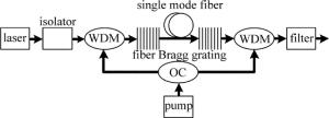
  • 超长分布式2阶喇曼放大器是通过使信号光在光纤传输系统中均匀传输来抑制放大自发辐射噪声的。它的系统结构如图 1所示。

    Figure 1.  Ultra-long distributed second-order Raman amplifier

    抽运光经过一个功率均分的光耦合器(optical coupler, OC)分为两路光分别通过两个波分复用器(wavelength division multiplexing, WDM)进入光纤。而进入光纤的抽运光在传输的过程中发生了受激喇曼散射效应,产生了1阶斯托克斯光。产生的1阶斯托克斯光的波长恰好等于所用光纤光栅的中心波长,这样在整个传输光纤上便可以产生大量该波长的激光。接着,光信号再经过隔离器之后通过波分复用器进入光纤。随着信号光在光纤上进行传输,产生的波长等于1阶斯托克斯光的大量激光通过受激喇曼散射效应对信号光进行放大。最后,在光纤的另一端,信号光经过一个中心波长等于信号光波长的光滤波器进行滤波。

    在传输的过程中,除了信号光与抽运光本身功率的衰减之外,放大自发辐射以及双瑞利散射也是需要考虑的会对功率产生影响的因素。对于以上提到的这些因素,各信号光、抽运光以及噪声的之间的关系可以见下式[12]:

    式中,下标+和-分别代表前向和背向传输方向,下标1, 2, s分别代表1阶抽运、2阶抽运和信号光,Pi(i=1, 2), Ps, Ns分别代表抽运功率、信号功率以及噪声功率,νi(i=1, 2, s)表示抽运光与信号光的频率值,Δνi(i=2, s)代表了信号与2阶抽运的有效带宽,gi(i=1, 2)是每一个喇曼转换的喇曼增益系数,αi(i=1, 2, s)是各频率的衰减系数,h是普朗克常数,KB是玻尔兹曼常数,T是绝对温度,εi(i=1, 2, s)是各频率的双瑞利散射系数。

    上述耦合方程组的边界条件如下:

    式中,P0表示前向以及背向抽运功率大小,一般情况下如(6)式所示两者相等,Pin表示信号光的初始功率、N0表示信号光的初始噪声功率,R1R2分别代表光纤两端的光纤光栅的有效反射率,L是传输光纤的长度。

2.   基于超长分布式2阶喇曼放大器的光载射频传输
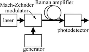
  • 将上述分布式2阶喇曼放大器用于光载射频传输,其结构如图 2所示。

    Figure 2.  Radio-over-fiber transmission link model based on ultra-long distributed second-order Raman amplifier

    对该系统采用的调制方式为一臂强度调制,另一臂光信号直接通过,则光信号和射频信号经过调制器,可以得到:

    式中,αMZM是调制器的插入损耗因子; E0为光源输出场强的最大值; ω0为光信号频率; $ \mathit{\Phi} \left( t \right) = \frac{{{\rm{ \mathsf{ π} }}{V_{{\rm{DC}}}}}}{{{V_{\rm{ \mathsf{ π} }}}}} + \frac{{{\rm{ \mathsf{ π} }}{V_{{\rm{RF}}}}(t)}}{{{V_{\rm{ \mathsf{ π} }}}}} $为调整后光信号的相位变化,其中,Vπ为调制器的半波电压,VDC是加在调制器上直流偏置电压,本文中取$ {V_{{\rm{DC}}}} = \frac{1}{2}{V_{\rm{ \mathsf{ π} }}} $,VRF(t)=VRFcos(ωRFt)为所调射频信号,ωRF是射频信号频率。

    在RoF链路中,信号光在光纤中的色散会对RoF系统造成影响[16-20]。链路中,射频信号调制到光信号的上下边带上,这两个边带之间有一定的频率,那么由于色散的影响将会产生相应的相位差。结合光纤损耗,并考虑光纤色散的影响,那么系统的传输函数可以写成[19]:

    式中,αloss=αlinkαMZM,整个RoF链路的总损耗,包括调制器的影响和光链路及其连接处引入的损耗; β2为光纤的2阶色散参量。

    对(7)式做贝塞尔展开,仅保留直流信号与1阶信号,做傅里叶变换,与(8)式的系统传输函数作用,将结果进行傅里叶逆变换,再考虑链路损耗以及超长分布式2阶喇曼放大器的增益,根据光电探测器的原理,可以得到光电探测器上产生1阶信号输出电流为:

    式中,η为光电探测器的响应度,P0=E02为光信号的光强,GR为喇曼放大器引入的增益,J1(m)为1阶贝塞尔函数,其中$ m = \frac{{{\rm{ \mathsf{ π} }}{V_{{\rm{RF}}}}(t)}}{{{V_{\rm{ \mathsf{ π} }}}}} $为调制度。

    1阶射频信号增益为[20]:

    式中,R为阻抗匹配时的电阻值。

3.   数值仿真
  • 首先,对1阶喇曼放大在80.94km范围内抽运光、信号光以及噪声的功率变化情况进行仿真分析,可以得到数值仿真结果如图 3所示,耦合方程见参考文献[11]。设置的仿真条件如下:传输距离L=80.94km、前向抽运光初始功率P+1(0)=267.1mW、背向抽运光初始功率P-1(L)=304.2mW、信号光初始功率Ps(0)=1.3mW、前向噪声初始功率N+s(0)=1.3×10⁻⁵mW、抽运光波长λ1=1537nm, 信号光波长λs=1625nm、1阶喇曼增益系数g1=0.279W-1·km-1、抽运光衰减系数α1=0.201dB·km-1、信号光衰减系数αs=0.206dB·km-1、抽运光双瑞利散射系数ε1=4.3×10⁻⁵km-1、信号光双瑞利散射系数εs=3.1×10⁻⁵km-1、信号光有效带宽Δνs=22.0GHz。
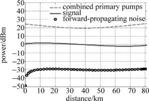
    Figure 3.  Relationship between distance and power of pumps, signal and noisewithin 80.94km under the first-order Raman amplifier

    在80.94km的传输距离上,总1阶抽运光整体对称,先下降再上升,信号光先上升再下降再上升,噪声则是先快速上升,再缓慢上升。整个过程中,信号光从1.13dBm下降到-1.01dBm,信号衰减为2.14dB,信号波动为3.83dB,前向噪声从-48.87dBm上升到了-29.05dBm,噪声恶化了20.95dB。此时的抽运波长为1537nm,抽运总功率为29.2dBm。

    接着,对80.94km范围内抽运光、信号光以及噪声的功率变化情况进行仿真分析。利用(1)式~(5)式中的耦合关系以及(6)式的边界条件,对L波段的超长分布式2阶喇曼放大器进行分析,可以得到数值仿真结果如图 4所示。设置的仿真条件如下:L=80.94km, P+1(0)=508.9mW, P-1(L)=579.6mW, Ps(0)=1.3mW, N+s(0)=1.3×10⁻⁵mW, R1=R2=0.99, λ1=1455nm, λ2=1537nm, λs=1625mm, g1=0.366W-1·km-1, g2=0.279W-1·km-1, α1=0.210dB·km-1, α2=0.201dB·km-1, αs=0.206dB·km-1, ε1=6.0×10⁻⁵km-1, ε2=4.3×10⁻⁵km-1, εs=3.1×10⁻⁵km-1, Δν2=55.5GHz, Δνs=22.0GHz。
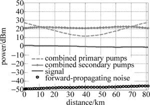
    Figure 4.  Relationship between distance and power of pumps, signal and noise within 80.94km under the second-order Raman amplifier

    在80.94km的传输距离上,总1阶抽运光及其产生的总2阶抽运光整体对称。总1阶抽运光先下降再上升,总2阶抽运光则分布比较均匀,在20dBm附近波动。信号光缓慢下降而噪声则缓慢上升,在80.94km的传输距离上实现了近似无损传输。在整个过程中,信号光从1.13dBm下降到-1.04dBm,信号衰减为2.17dB,信号波动为2.17dB,前向噪声从-48.87dBm上升到-45.57dBm,噪声恶化了3.30dB。与1阶喇曼放大的情况相比,达到同样的放大效果的抽运功率更高,即能量转化效率更低。但是,信号光的波动范围更小,放大器所产生的ASE噪声更小,即噪声性能更差。

    然后,对0GHz~7GHz范围内RoF系统的频率响应及其射频增益进行仿真分析。根据(10)式,通过数值计算可以得到图 5。能清晰地看到在该范围内,射频信号功率受光纤色散的影响较小,并且喇曼放大器的放大后的结果较明显。取η=0.4A/W,αloss=-19.17dB,GR=14.49dB,P0=1.27dBm,R=50Ω,Vπ=6V,β2=27.8ps2·km-1L=80.94km,可以得到抽运功率为32dBm时0GHz~7GHz范围内的频率响应。而取GR=0dB,可以得到抽运功率为0dBm时0GHz~7GHz范围内的频率响应。这两条曲线在0GHz~7GHz范围内均是先上升再下降,3dB带宽为5.9GHz,这是由于光信号在光纤中传输时发生了色散,造成了作为边带的射频信号功率的衰落,其衰落程度受射频信号频率的影响。而点划线则表示射频信号开关增益受射频信号频率的影响,在0GHz~7GHz范围内射频信号开关增益均为29.0dB,即该系统的射频增益在较宽的范围内保持平坦。

    Figure 5.  Simulation relationship between frequency and the first-order gain of radio-over-fiber transmission link ranging from 0GHz to 7GHz

4.   实验验证
  • 图 6是基于超长分布式2阶喇曼放大器的光载射频传输的实验结构图。即将图 1所示的放大器部分作为RoF系统的传输链路,实验中所用器件的参量如图 6中标注所示。
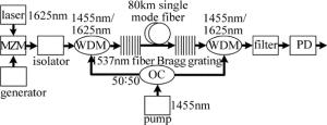
    Figure 6.  Radio-over-fiber transmission links based on ultra-long distributed second-order Raman amplifier

    保持射频信号频率为1GHz,射频信号功率为0dBm,设置抽运功率从30.0dBm~32.6dBm进行变化,可以得到图 7图 7表示抽运功率大小对超长分布式2阶喇曼放大器的开关增益的影响,其中实线为数值计算的结果,散点为实验测试的结果。从数值计算结果可以看到,随着抽运功率的不断增大,放大器的开关增益变得越来越大,且与抽运功率增加的大小成比例关系。从实验测得的结果可以较好地与数值计算的结果相互匹配。实验中测量得到的放大器的开关增益与数值计算的结果有1dB左右的差距,这可能是由于所使用的抽运光源输出功率不稳定造成的。在抽运功率为32.0dBm处,实验测量的开关增益为14.1dB,而抽运功率为0dB时整个光链路的损耗为17.8dB,那么整个光链路的损耗为3.7dB,说明该光载射频传输系统在80.94km的传输距离上可以实现信号光近似无损的传输。
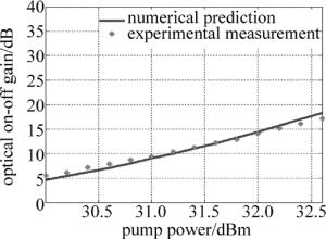
    Figure 7.  Relationship between on-off gain of ultra-long distributed second-order Raman amplifier and pump power

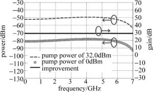
    保持抽运功率为32.0dBm,设置射频信号频率从100MHz~7GHz进行变化,可以得到图 8图 8为0GHz~7GHz范围内RoF系统的频率响应及其射频增益的实验结果。从图 8中可以看到,当不接抽运光源以及接入抽运光源时,RoF系统的频率幅度响应在0GHz~7GHz范围内均是先上升再下降,3dB带宽为5.8GHz,与图 4中数值仿真结果符合。对比两种情况,得到射频增益曲线,其射频增益约为28.1dB,与其数值仿真结果有0.9dB的差距,这也是由于所使用的抽运光源输出功率不稳定造成的,基本可以说明射频增益在较宽的范围内保持平坦。
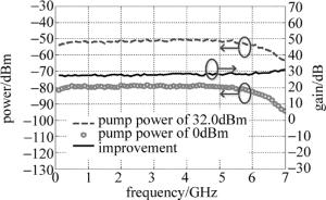
    Figure 8.  Experimental relationship between frequency and the first-order gain of radio-over-fiber transmission link ranging from 0GHz to 7GHz

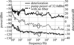
    图 9为RoF链路的在射频频率为1GHz、抽运功率为32.0dBm以及无传输光纤时的相位噪声情况。从图 9中可以看到,加入超长分布式2阶喇曼放大器后,链路的相位噪声性能在整体范围内均有恶化,这是由于抽运光源的不稳定以及光纤中色散带来的。但是也可以看到,随着与中心频率偏移量的增大,相位噪声恶化的程度从37.6dB下降到12.8dB,说明该RoF系统导致相位噪声的恶化在远离中心频率处较小。

    Figure 9.  Phase noise of radio-over-fiber transmission link with pump power of 32.0dBm and 0dBm

5.   结论
  • 针对L波段的超长分布式2阶喇曼放大器进行了研究,并提出了一种基于超长分布式2阶喇曼放大器的光载射频传输方案。从理论上对分布式2阶喇曼放大器以及光载射频传输链路进行了分析,得到了信号光、抽运光以及噪声之间的耦合方程和光载射频传输系统的1阶射频信号增益。通过数值仿真以及系统实验对该结构进行了验证。数值仿真以及实验结果均表明,该系统在光链路上实现了近似无损传输,射频增益在较宽的范围内保持平坦。实验结果也表明,该RoF系统导致相位噪声的恶化在远离中心频率处较小。最终,光载射频传输在超长分布式2阶喇曼放大器的作用下在80.94km的传输距离上获得了28.1dB的链路增益。

Reference (20)

Catalog

    /

    DownLoad:  Full-Size Img  PowerPoint
    Return
    Return