Advanced Search

ISSN1001-3806 CN51-1125/TN Map

Volume 42 Issue 1
Jan.  2018
Article Contents
Turn off MathJax

Citation:

Study on characteristics of bent photonic crystal waveguides with resonant cavities

  • Received Date: 2017-01-22
    Accepted Date: 2017-04-13
  • In order to study high performance filters based on photonic crystal waveguide, some methods such as adjusting the structures of resonant cavities and optimizing the coupling regions were adopted in the paper. Three kinds of bent photonic crystal waveguides were designed based on the coupled-mode theory in square dielectric rod photonic crystal. After theoretical analysis and experimental verification, the performance characteristics in the S-band and C-band were studied by the time-domain finite-different method. The results show that, 3 kinds of waveguides have good band stop or band pass characteristics at different wavelengths. Cutoff transmission wavelength and passband transmission wavelength shift toward longer wavelengths with the increase of relative dielectric constant of the overall dielectric column. Cutoff wavelength and transmission wavelength are increased by about 6nm with the increase of dielectric constant εr by 0.3. The study has potential value in the designs of micro optical sensors, micro optical communication devices, optical integrated circuits, etc.
  • 加载中
  • [1]

    YABLONOVITCH E. Inhibited spontaneous emission in solid-state physics and electronics[J]. Physical Review Letters, 1987, 58(20):2059-2062. doi: 10.1103/PhysRevLett.58.2059
    [2]

    SAJEEV J. Strong localization of photons in certain disordered dielectric superlattices[J]. Physical Review Letters, 1987, 58(23):2486-2489. doi: 10.1103/PhysRevLett.58.2486
    [3]

    HEMANT S D, AMIT K G, VARUN S, et al. Coupling light in photonic crystal waveguides:A review[J]. Photonics and Nanostructures Fundamentals and Applications, 2016, 20(1):41-58.
    [4]

    BABA T. Slow light in photonic crystals[J]. Nature Photonics, 2008, 2(8):465-473. doi: 10.1038/nphoton.2008.146
    [5]

    ZHOU J, TIAN H P, YANG D Q, et al. Ultra-broadband and ultra-low-loss photonic crystal with band-flatness waveguide 60 bend obtained based on lattice-shifted optimization[J]. Optics Communications, 2014, 322(1):227-233.
    [6]

    YUAN J H, YANG J, SHI D, et al. Design optimization of a low-loss and wide-band sharp 120° waveguide bend in 2-D photonic crystals[J]. Optics Communications, 2016, 367(1):356-363.
    [7]

    DANAIE M, ATTARI A R, MIRSALEHI M M, et al. Design of a high efficiency wide-band 60° bend for TE polarization[J]. Photonics and Nanostructures-Fundamentals and Applications, 2008, 6(3):188-193.
    [8]

    ROSA L, SAITOH K, KAKIHARA K, et al. Genetic-algorithm assisted design of C-band CROW-miniaturized PCW interleaver[J]. Journal of Lightwave Technology, 2009, 27(14):2678-2687. doi: 10.1109/JLT.2009.2014883
    [9]

    LU M F, YANG Y L, HUANG Y T. Numerical study of transmission improvement in a photonic crystal waveguide bend by mode-matching technique[J]. IEEE Photonics Technology Letters, 2008, 20(24):2114-2116. doi: 10.1109/LPT.2008.2006918
    [10]

    BETTINI P, BOSCOLO S, SPECOGNA R B, et al. Design optimization of waveguide bends in photonic crystals[J]. IEEE Transactions on Magnetics, 2009, 45(3):1630-1633. doi: 10.1109/TMAG.2009.2012761
    [11]

    TEE D C, YU G, SHEE N Z, et al. Structure tuned, high transmission 180° waveguide bend in 2-D planar photonic crystal[J]. IEEE Photonics Technology Letters, 2013, 25(15):1443-1446. doi: 10.1109/LPT.2013.2266893
    [12]

    LIU Y F, LIU B, CHEN J, et al. Study on filtering characteristics based on tooth-shaped photonic crystal waveguide[J]. Laser Technique, 2016, 40(2):237-240(in Chinese).
    [13]

    ESPINOLA R, AHMAD R, PIZZUTO F, et al. A study of high-index-contrast 90°waveguide bend structures[J]. Optics Express, 2001, 8(9):517-528. doi: 10.1364/OE.8.000517
    [14]

    PEI H Ch, LI B, DANNER A J, et al. Design and modeling of 2-D photonic crystals based hexagonal triple-nano-ring resonators as biosensors[J]. Microsystem Technologies, 2013, 19(1):53-60. doi: 10.1007/s00542-012-1610-1
    [15]

    POPESCU D, STERIAN P. FDTD analysis of photonic crystals with square and hexagonal symmetry[J]. Journal of Advanced Research in Physics, 2011, 2(2):1-5.
    [16]

    CHANG K, LIU Ch Y. Electro-optical channel drop switching in a photonic crystal waveguide-cavity side-coupling system[J]. Optics Communications, 2014, 316(7):10-16.
    [17]

    HUANG H, OUYANG Zh B. General method for eliminating wave reflection in 2-D photonic crystal waveguides by introducing extra scatterers based on interference cancellation of waves[J]. Optics Communications, 2016, 370(9):55-59.
    [18]

    PILEHVAR E, KAATYZIAN H, DANAIE M. Design of a high-transmission waveguide bend for Kagome photonic crystal lattice[J]. Optik-International Journal for Light and Electron Optics, 2015, 126(19):1914-1917. doi: 10.1016/j.ijleo.2015.05.042
    [19]

    ZHU Zh M, BROWN T G. Full-vectorial finite-difference analysis of microstructured optical fibers[J]. Optics Express, 2002, 10(17):853-864. doi: 10.1364/OE.10.000853
    [20]

    LÜ Sh Y, ZHAO H. Design and research of wavelength division demultiplexer based on slow light waveguides. Laser Technology, 2015, 39(5):617-620(in Chinese).
    [21]

    HALL K, LENZ G, DARWISH M A, et al. Subpicosecond gain and index nonlinearities in InGaAsP diode lasers[J]. Optics Communications, 1994, 111(5):589-612.
    [22]

    GHAFFARI A, DJAVID M, MONIFI F, et al. Photonic crystal power splitter and wavelength multi/demultiplexer based on directional coupling[J]. Journal of Optics, 2008, A10(7):75203-75209.
    [23]

    GHAFFARI A, MONIFI F, DIAVID M, et al. Photonic crystal bends and power splitters based on ring resonators[J]. Optics Communications, 2008, 281(23):5929-5934. doi: 10.1016/j.optcom.2008.09.015
    [24]

    GHAFFARI A, MONIFI F, DIAVID M, et al. Analysis of photonic crystal power splitters with different configurations[J]. Journal of Applied Sciences, 2008, 8(8):1416-1425. doi: 10.3923/jas.2008.1416.1425
    [25]

    DINESH K V, TALABUTTULA S, SELVARAJAN A. Investigation of ring resonators in photonic crystal circuits[J]. Photonics and Nanostructures-Fundamentals and Applications, 2004, 2(3):199-206.
    [26]

    GHAFARI A, DJAVID M, MONIFI F, et al. A numeric analysis of photonic crystal tunable add-drop filters based on ring resonators[C]//IEEE LEOS Annual Meeting. New York, USA: IEEE, 2007: 351-352.
    [27]

    GOLDBERG M. Stability criteria for finite difference approximations to parabolic systems[J]. Applied Numerical Mathematics, 2000, 33(1/4):509-515.
    [28]

    BERENGER J P. A perfectly matched layer for the absorption of electromagnetic waves[J]. Journal of Computational Physics, 1994, 114(2):185-200. doi: 10.1006/jcph.1994.1159
  • 加载中
通讯作者: 陈斌, bchen63@163.com
  • 1. 

    沈阳化工大学材料科学与工程学院 沈阳 110142

  1. 本站搜索
  2. 百度学术搜索
  3. 万方数据库搜索
  4. CNKI搜索

Figures(12)

Article views(8075) PDF downloads(387) Cited by()

Proportional views

Study on characteristics of bent photonic crystal waveguides with resonant cavities

  • School of Physics Science & Information Engineering, Liaocheng University, Liaocheng 252059, China

Abstract: In order to study high performance filters based on photonic crystal waveguide, some methods such as adjusting the structures of resonant cavities and optimizing the coupling regions were adopted in the paper. Three kinds of bent photonic crystal waveguides were designed based on the coupled-mode theory in square dielectric rod photonic crystal. After theoretical analysis and experimental verification, the performance characteristics in the S-band and C-band were studied by the time-domain finite-different method. The results show that, 3 kinds of waveguides have good band stop or band pass characteristics at different wavelengths. Cutoff transmission wavelength and passband transmission wavelength shift toward longer wavelengths with the increase of relative dielectric constant of the overall dielectric column. Cutoff wavelength and transmission wavelength are increased by about 6nm with the increase of dielectric constant εr by 0.3. The study has potential value in the designs of micro optical sensors, micro optical communication devices, optical integrated circuits, etc.

引言
  • 光子晶体能把带隙中的电磁波信号约束在设定好的波导内传输[1-4],并将其传输到指定位置,以便对传送的信号进行分析处理。因此,设计高品质工作性能的波导结构在信号接收与传递、超低功耗、高带宽等方面具有重要的研究意义[5-6]。近年来,很多研究都是围绕着解决2维光子晶体波导弯折角设计开展的,有的学者[7-8]采用了改变弯折处空气孔或介质棒半径的方法来改变通过性能;有的研究[9-10]同时改变了光子通道半径及弯折处介质棒的位置,达到了更佳的通过性;还有学者[11-12]提出引入孔洞缺陷的方法,通过缺陷产生共振频率实现了窄带滤波或宽带滤波的良好效果。经典集成光学通过在波导弯折处采用隅角反射镜结构或开放式谐振腔结构来改善其传输性能,其类似结构也可以应用于改善光子晶体波导对电磁波的传输性能[13-18]。在上述研究的基础上,在正方格介质柱光子晶体中通过设置谐振腔等结构来调节波导的工作性能,通过耦合模理论优化设计了L型、U型、S型弯折波导。有学者应用时域有限差分法[19-20]编程研究了这3种波导结构对平行极化波的传输特性,通过分析3种波导结构的传输谱、输入反射谱、电场强度分布图发现,3种结构在不同的波段均具有良好的带阻滤波特性和带通滤波特性,且其截止传输波长和通带传输波长随整体介质柱相对介电常数增加向长波方向移动。这些性质在微型光滤波器设计、微型光传感器、微型光通信器件设计及集成光路设计中具有较大研究意义。

1.   耦合模理论设计弯折波导上的应用
  • 运用时域耦合模理论(coupled-mode theory, CMT)[21-24]进行了谐振腔与波导之间理论上的耦合特性分析,设计了3种带有谐振腔的弯折波导结构。瞬时CMT理论基于输入及输出的电磁场通量平衡的一瞬时微分方程, 在理想传输状况下没有损耗,设在谐振腔内场的振动频率是ω0,振幅是a(t),S+1描述了波导端口P1的电磁波输入能量,S-1S-2分别描述了波导端口P1和P2的电磁波输出能量。取振幅a(t)时间导数得:

    式中, 1/τ1, 1/τ2为耦合到输入和输出两波导模式振幅衰减率,1/τ0为腔损耗衰减率, K1为耦合系数。相关的外部耦合因子为:

    谐振腔固有品质因子为:

    固有品质因子Q0描述了由于谐振腔可向周围结构传输功率泄露而造成的能量固有损耗,外部耦合因子Qe, 1Qe, 2描述了腔与波导耦合作用时能量的泄露。耦合系数K1依赖于输入波导模式振幅衰减率1/τ1,两个量之间的关系为:

    通过波导模式与谐振器模式的强耦合作用辐射效应被削弱,在腔与波导模式强耦合的状况下,耦合模理论为这个概念提供了一种定性描述。按照耦合模理论能获得如下的关系式,端口P1的反射率为:

    式中,ω为腔外频率。端口P2的传输率为:

    在一无损耗介质和对称的系统中,1/τ0=0,1/τ1=1/τ2=1/τe=ω0/(2Qe),系统具有100%的传输率,1/τ0≠0时,数值比τe/τ0=Qe/Q0决定最大传输率与最小反射率,得到如下的公式:

    传输损耗率为:

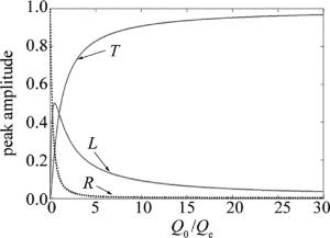
    图 1中给出传输率、反射率、传输损耗率随Q0/Qe变化的关系图像。很明显,如果谐振器无辐射损耗,在谐振频率上能实现没有反射的完全传输,然而辐射损失是不可避免的,将会减小传输率,通过制作非常大的Q0/Qe,来实现波导模式与谐振腔模式间的强耦合作用,以提高传输率。

    Figure 1.  Transmission, reflection and losses with the change of Q0/Qe

2.   带有谐振腔的弯折光子晶体波导
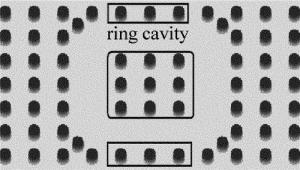
  • 从正方格介质柱光子晶体中抽取其中的部分介质柱,形成介质柱围绕的环形结构腔,并在环形腔的4个拐角半个晶格常数处分别放置一支相同散射介质柱[25],形成图 2所示的一种典型的近圆环形结构谐振腔。腔内有一个3×3介质柱结构,画在圆角长方框内部,腔外侧两排耦合区域介质柱画在两个长方框内部。也可在光子晶体结构内部直接抽取其中的一排介质柱,形成形式上更为简化的线形谐振腔结构。

    Figure 2.  Rring cavity of photonic crystal

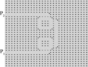
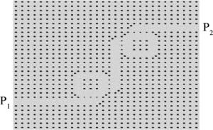
    在晶格常数a=541nm、介质柱半径r=0.2a, 30×30的2维正方格子介质柱光子晶体中,通过调节环形谐振腔和线形谐振腔结构、波导与谐振腔耦合区域、谐振腔间耦合区域及其介电常数设值等,优化设计了波导的工作特性。根据耦合模理论设计了具有轴对称、中心对称结构的弯折波导。图 3~图 11是在光子晶体中设计的L型、U型、S型波导结构示意图。圆斑代表介质柱,其相对介电常数εr=11.6,介质柱周围区域为空气,其εr值近似为1。为改善其传输特性[26],在光子晶体中波导拐角和线形谐振腔拐角的半个晶格常数处分别放置了半径为r的介质柱,且使波导与谐振腔耦合区域,及谐振腔之间的耦合区域介质柱半径为rc=0.8r。把该结构的每个正方格子原胞分成20×20等分,使其数值计算满足Courant稳定性条件[27],并在其结构周围使用了完全匹配层(perfectly matched layer,PML)[28]作为吸收边界,以便将透射的电磁波吸收掉。

    Figure 3.  Structure block of L-shaped bent photonic crystal waveguide

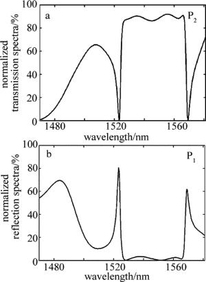
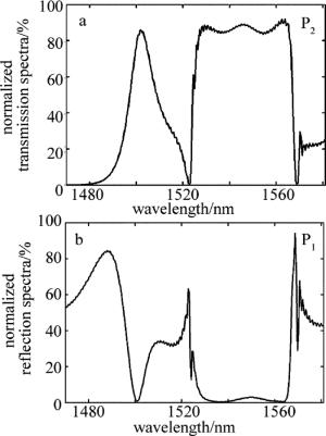
    Figure 4.  Normalized spectra of L-shaped bent photonic crystal waveguide

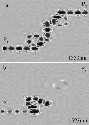
    Figure 5.  Structure block and characteristic graph of L-shaped bent photonic crystal waveguide

    Figure 6.  Structure block of U-shaped bent photonic crystal waveguide

    Figure 7.  Normalized spectra of U-shaped bent photonic crystal waveguide

    Figure 8.  Structure block and characteristic graph of U-shaped bent photonic crystal waveguide

    Figure 9.  Structure block of S-shaped bent photonic crystal waveguide

    Figure 10.  Normalized spectra of S-shaped bent photonic crystal waveguide

    Figure 11.  Structure block and characteristic graph of S-shaped bent photonic crystal waveguide

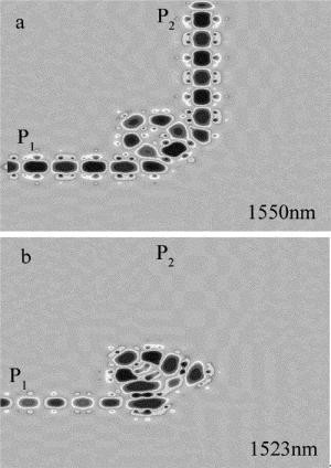
  • 利用一个环形结构谐振腔和2支波导,设计了图 3所示L型波导结构。图 4a图 4b给出了L型波导P2端口归一化功率传输谱和P1端口归一化功率反射谱,即波导中归一化传输功率和归一化反射功率随波长的变化关系。如图 4a所示, 在1523nm波长处传输率为0.3%,波导工作于截止传输状态。该波长左侧有一S波段(1460nm~1523nm)上的通带,其传输率最大值与对应传输波长分别为66.7%, 1502nm;该波长右侧有一传输通带1525nm~1568nm,在整个C波段(1525nm~1568nm)上其反射率最大值为3.4%、传输率最小值为86.1%。图 5a图 5b给出了L型光子晶体波导传输状态和截止传输状态的电场强分布图,其输出波长1550nm与截止传输波长1523nm在图中已标出。图 5所示波导结构工作于传输状态,该波通过环形腔弯折90°后输出;图 5b所示其结构工作于截止传输状态,由图 4a图 4b可知:输入的波经环形谐振腔后绝大部分沿输入波导返回。

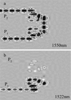
  • 在两环形结构谐振腔上下端水平方向放置了两支波导,并在其右侧放置了一个线形结构谐振腔,组成了图 6所示的U型波导结构。图 7a图 7b给出了U型光子晶体波导的功率传输谱及其反射谱。由图可得输出端口在1522nm波长处传输率为1.4%,该波导工作于截止传输状态。该波长左侧有一S波段上的通带,其传输率最大值与对应传输波长分别为88.2%, 1503nm;该波长的右侧通带也处于1525nm~1568nm,在整个C波段上,其反射率最大值为3.2%,传输率最小值为86.2%。图 8a所示U型波导工作于1550nm波长的传输状态,两次通过环形腔,弯折180°后输出。图 8b所示在1522nm波长,波导工作于截止传输状态。

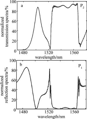
  • 在两环形结构谐振腔上下端水平方向放置了两支波导,并在其中间放置了一个线形结构谐振腔,组成了图 9所示的S型波导结构。图 10a图 10b给出了S型光子晶体波导的功率传输谱及其反射谱。由图可知,输出端口在1523nm波长处传输率为1.4%,该波导工作于截止传输状态。该波长左侧有一S波段上的通带,其传输率最大值与对应传输波长分别为85.9%, 1503nm;该波长的右侧通带也处于1525nm~1568nm,在整个C波段上,其反射率最大值为2.9%,传输率最小值为83.6%。图 11a所示S型波导工作于1550nm波长的传输状态,先后两次通过环形谐振腔,逆时针方向和顺时针方向各弯折90°后输出。图 11b所示波导工作于1523nm波长,处于截止传输状态。

    当L型、U型、S型波导结构的整体介质柱相对介电常数值为11.6,通过计算给出了TM波在波导输出端口P2处功率传输谱和输入端口P1处功率反射谱及其电场强度分布图。通过比对L型、U型、S型3种波导的输出谱曲线和反射谱曲线,不难发现在1460nm~1523nm波段(属S波段),3种波导均具有一定的带通滤波特性。其中,L型波导曲线变化更缓,具有较大的通带,而U型和S型因发生了两次90°弯折,因此传输谱曲线变化更陡峭,具有更好的选频特性,通带较窄。在1522nm~1523nm波长附近,3种波导结构均具有优良的窄带带阻滤波特性,使波导处于截止传输状态。其中,L型带阻滤波通带较窄,传输率为0.3%,U型和S型带阻通带较宽,传输率均为1.4%。在第三通信窗口1525nm~1568nm波段(属C波段),3种波导的传输谱特性相似,具有优良的带通滤波特性,波导工作与传输状态,所在的通带具有带边沿陡峭、幅度平稳、通带波长宽裕、传输率高、大角度弯折传输等特性。其中,L型和U型波导传输率最小值分别为86.1%和86.2%,而S型波导略低,为83.6%。它们工作时产生的电场强度分布图,在其背景上都有轻微的波纹,这是一小部分电磁波泄露产生的结果,最后被设置在周围的PML层吸收掉。因此,可根据上述3种波导传输特性的不同,在对通带及滤波效果不同的需求中选择使用。

3.   整体介质柱介电常数改变对波导传输特性的影响
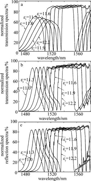
  • 图 12依次给出了L型、U型、S型波导整体介质柱不同相对介电常数εr值时端口P2输出功率传输谱的变化特征(其不同相对介电常数值已用不同线型标出)。图 12a给出了L型波导整体介质柱εr值分别为11.0, 11.3, 11.6, 11.9, 12.2时,输出端口对应的传输通带波长为1512nm~1555nm, 1518nm~1561nm, 1525nm~1568nm, 1531nm~1574nm, 1537nm~1580nm,且变化过程中1550nm波长的传输率位于86.9%到91.8%之间;对图 12b图 12c可进行同样的分析。结果表明:这3种波导在设置的介电常数取值范围中,对1550nm波长始终保持高传输率、及其通带边沿陡峭、幅度平稳的工作特性,且波导的通带波长移动和截止传输波长移动随εr值每增加0.3向长波方向移动6nm左右,近似成正比例关系。在1510nm~1536nm波长上,两紧邻传输率峰值之间具有优良的窄带带阻滤波特性,使波导截止传输其对应波长。制作波导材料的介电常数受到外界环境的影响(如温度、电磁场等)会产生变化,可利用外界环境变化产生的影响(热光效应、电光效应等)去调制结构中εr的值,使端口P2截止输出波长发生移动。因此,其波导结构可作为微型带阻传感器、或光学开光来使用,以检测周围的环境状况。

    Figure 12.  Normalized transmission spectra at the output port P2

4.   结论
  • 根据耦合模理论在2维正方格子介质柱光子晶体中,通过调节谐振腔结构、波导与谐振腔耦合区域、谐振腔间耦合区域、介电常数设值等方式优化设计了L型、U型、S型波导的工作特性。利用时域有限差分法研究了其结构整体介质柱相对介电常数εr在11.0~12.2时波导结构对TM波的传输特性。结果表明:在结构整体介质柱εr=11.6时,在1460nm~1523nm波段,3种波导均具有一定的带通滤波特性。其中,L型波导具有较大的通带,而U型和S型波导具有更好的选频特性,通带较窄。在1522nm~1523nm波长附近,3种波导结构均具有优良的窄带带阻滤波特性。其中,L型带阻滤波通带较窄,传输率为0.3%,U型和S型带阻通带较宽,传输率均为1.4%。在1525nm~1568nm波段,3种波导的传输谱特性相似,具有良好的带通滤波特性。其中,L型和U型波导传输率最小值分别为86.1%和86.2%,而S型波导略低,为83.6%。因此,可根据3种波导的传输特性,设计成不同需求的滤波器。此外,这3种波导在设置的εr取值范围中对1550nm波长始终保持高传输率、及其通频带左右边沿陡峭的工作特性,且波导的截止传输波长和通带传输波长随εr值每增加0.3向长波方向移动6nm左右,其变化近似成正比例关系。其结构在微型光传感器制作、微型光通信器件制作、集成光路的设计等方面具有潜在价值。

Reference (28)

Catalog

    /

    DownLoad:  Full-Size Img  PowerPoint
    Return
    Return