Advanced Search

ISSN1001-3806 CN51-1125/TN Map

Volume 42 Issue 1
Jan.  2018
Article Contents
Turn off MathJax

Citation:

Monitoring scheme of polarization mode dispersion based on pulse position modulation system

  • Corresponding author: LUO Fengguang, fgluo@mail.hust.edu.cn
  • Received Date: 2017-03-24
    Accepted Date: 2017-04-01
  • In order to monitor polarization mode dispersion (PMD) of the fiber communication channel in a pulse position modulation (PPM) transmission system dynamically, a novel PMD monitoring method was proposed based on single sideband polarization phase difference detection technology, and the mathematical model of the method was built in accordance with monitoring principle. The structure of the method was simple, so it can be realized easily at very low cost. The simulation results indicate that the method can realize dynamic PMD monitoring including differential group delay (DGD) and polarization state of output light, and the technique can monitor DGD accurately in the range of 0ps to 100ps. It is proved that the operation of proposed PMD monitor method is independent of data rates, which shows the proposed method can satisfy the need of real time PMD monitoring for PPM transmission systems. It indicates that the proposed method is feasible and effective for PMD monitoring.
  • 加载中
  • [1]

    LI B. Investigation of dispersion monitoring technology for ultra-high speed optical transmission link[D].Wuhan: Huazhong University of Science and Technology, 2012: 75-102(in Chinese).
    [2]

    ZHANG L, CHRISTEN L C, ZHANG B, et al. Polarization-mode dispersion monitoring for phase-modulated signals using DGD-genera-ted interferometric filter[J]. IEEE Photonics Technology Letters, 2008, 20(2):150-152. doi: 10.1109/LPT.2007.912505
    [3]

    DENG N, CHAN C K, CHEN L K. A hybrid OTDM scheme with enhanced demultiplexing performance[J]. IEEE Photonics Technology Letters, 2007, 19(19):1454-1456. doi: 10.1109/LPT.2007.903967
    [4]

    ZHAO J, CHEN L K, CHAN C K. A novel re-modulation scheme to achieve colorless high-speed WDM-PON with enhanced tolerance to chromatic dispersion and re-modulation misalignment[C]//Optical Fiber Communication and the National Fiber Optic Engineers Conference, 2007. New York, USA: IEEE, 2007: 1-3.
    [5]

    LEE J H, YOSHIKANE N, TSURITANI T, et al. In-band OSNR monitoring technique based on link-by-link estimation for dynamic transparent optical networks[J]. Journal of Lightwave Technology, 2008, 26(10):1217-1225. doi: 10.1109/JLT.2008.917060
    [6]

    LEE J H, GUO H, TSURITANI T, et al. Field trial of all-optical networking controlled by intelligent control plane with assistance of optical performance monitors[J]. Journal of Lightwave Technology, 2009, 27(2):94-100. doi: 10.1109/JLT.2008.928522
    [7]

    GRUPP W. Monitoring requirements for optical transparent networks[C]//Optical Fiber Communication Conference, 2006 and the 2006 National Fiber Optic Engineers Conference. New York, USA: IEEE, 2006: OWN5.
    [8]

    FLORIDIA C, SIMÕES G C, FERES M M, et al. Simultaneous optical signal-to-noise ratio and differential group delay monitoring based on degree of polarization measurements in optical communications systems[J]. Applied Optics, 2012, 51(17):3957-3965. doi: 10.1364/AO.51.003957
    [9]

    YANG J, YU C, CHENG L, et al. CD-insensitive PMD monitoring based on RF power measurement.[J]. Optics Express, 2011, 19(2):1354-1359. doi: 10.1364/OE.19.001354
    [10]

    BUCHALI F, BAUMERT W, BULOW H, et al. A 40Gb/s eye monitor and its application to adaptive PMD compensation[C]//Optical Fiber Communication Conference and Exhibit. New York, USA: IEEE, 2002: 202-203.
    [11]

    LI Z, LI G. In-line performance monitoring for RZ-DPSK signals using asynchronous amplitude histogram evaluation[J]. IEEE Photonics Technology Letters, 2006, 18(3):472-474. doi: 10.1109/LPT.2005.861968
    [12]

    KOZICKI B, TAKUYA O, HIDEHIKO T. Optical performance monitoring of phase-modulated signals using asynchronous amplitude histogram analysis[J].Journal of Lightwave Technology, 2008, 26(10):1353-1361. doi: 10.1109/JLT.2008.917374
    [13]

    JARGON J A, WU X, WILLNER A E. Optical performance monitoring by use of artificial neural networks trained with parameters derived from delay-tap asynchronous sampling[C]//Optical Fiber Communication-Incudes Post Deadline Papers, 2009. New York, USA: IEEE, 2009: 1-3.
    [14]

    HE Ch, LUO F G, LI B. Dispersion measuring technique based on second order lowest power of radio frequency signal[J]. Laser Technology, 2017, 41(2):169-173(in Chinese).
    [15]

    CAO X. Optimization of dispersion compensation in optical fiber communication systems[J]. Laser Technology, 2014, 38(1):101-104(in Chinese).
    [16]

    HU J B, LI M P. Design of novel tunable semiconductor lasers in optical fiber communication systems[J]. Laser Technology, 2016, 40(2):280-283(in Chinese).
  • 加载中
通讯作者: 陈斌, bchen63@163.com
  • 1. 

    沈阳化工大学材料科学与工程学院 沈阳 110142

  1. 本站搜索
  2. 百度学术搜索
  3. 万方数据库搜索
  4. CNKI搜索

Figures(8)

Article views(5801) PDF downloads(223) Cited by()

Proportional views

Monitoring scheme of polarization mode dispersion based on pulse position modulation system

    Corresponding author: LUO Fengguang, fgluo@mail.hust.edu.cn
  • School of Optoelectronic and Electronic Information, Huazhong University of Science and Technology, Wuhan 430074, China

Abstract: In order to monitor polarization mode dispersion (PMD) of the fiber communication channel in a pulse position modulation (PPM) transmission system dynamically, a novel PMD monitoring method was proposed based on single sideband polarization phase difference detection technology, and the mathematical model of the method was built in accordance with monitoring principle. The structure of the method was simple, so it can be realized easily at very low cost. The simulation results indicate that the method can realize dynamic PMD monitoring including differential group delay (DGD) and polarization state of output light, and the technique can monitor DGD accurately in the range of 0ps to 100ps. It is proved that the operation of proposed PMD monitor method is independent of data rates, which shows the proposed method can satisfy the need of real time PMD monitoring for PPM transmission systems. It indicates that the proposed method is feasible and effective for PMD monitoring.

引言
  • 信息时代的到来,使得人们对于高速通信系统的要求越来越迫切。光通信系统凭借其高速率、大容量、低损耗、抗干扰、保密性强和材料来源充足等优势,在通信领域得到广泛应用。然而在超高速光传输链路中,偏振模色散(polarization mode dispersion,PMD)效应极大地限制了系统性能[1]。传统的PMD监测方案无法满足高速传输链路的要求[2],因此光性能监测成为一个热点问题[3-6]。PMD监测解决方案可以分为主动式和被动式[7]。被动式主要是采用特殊的传输方式和高级调制格式等方式,提高系统的PMD容限,以尽量降低PMD效应对系统性能的影响;但被动式方案难以起到良好的监测效果,故而研究者多采用主动式补偿方案。

    由于PMD是随机变化的,并且对于环境变化十分敏感,因此必须进行动态补偿才能达到理想的效果。对实时的PMD动态监测的研究具有重要的意义。大多PMD补偿方案都是基于反馈调节以实现动态的补偿,这使得PMD补偿变得异常复杂。基于反馈调节补偿的PMD补偿方案主要有:频谱分析法、眼图法、相位差法、副载波导频法等[8-13]。频谱分析法分为单频法和频带法,前者不适用于传输速率较高的传输系统;后者通用性差,升级困难。眼图法缺点是当信号的误比特率较低时,对差分群延时探测的灵敏度不足,难以适应高速链路下PMD监测的要求。相位差法监测范围较小,对较大的PMD或者较小的PMD难以进行有效监测。副载波导频法是基于性能最差的信道进行补偿,因此对于其它信道补偿效果难以保证。

    本文中研究的主要目的是进行链路PMD实时监测,以此给动态补偿提供补偿[14-15]依据。因此作者提出了一种基于单边带频谱内不同偏振信号相位差的PMD监测方案,针对脉冲位置调制(pulse position modulation,PPM)系统的1阶PMD进行实时监测。仿真结果表明, 该方案对于PMD的实时监测,受链路速率的影响较小,适应性较好, 且该方案结构简单、对器件性能要求低、监测范围相对较广、能有效降低PMD实时监测的成本。

1.   PMD监测原理
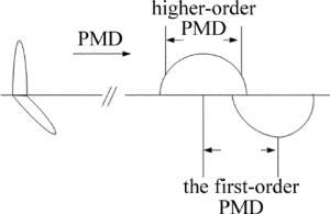
  • 图 1为PMD对可调谐激光器[16]产生的光信号的脉冲影响示意图。PMD会造成不同偏振信号间的时延,进而使脉冲展宽,最终降低系统传输性能。在高速通信系统中,1阶PMD效应是造成的传输性能劣化的主要原因,因此本文中针对1阶PMD效应的监测提出了一种有效的方案。PMD效应对信号的影响主要是改变信号的相位值,通常情况下,会用光纤中不同偏振信号的群时延差来表示光纤中PMD的大小,即差分群延时(differential group delay,DGD)。基于单边带频谱内不同偏振信号相位差的PMD监测方案,其原理为通过计算不同偏振光信号的相位差值,以实现PMD监测的目的。

    Figure 1.  The impact of PMD on optical signal

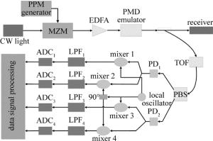
    本文中所提出的监测系统原理如图 2所示。首先通过马赫-曾德尔调制器将产生的PPM调制信号调制到光载波上,然后使用PMD模拟器对信号加载DGD,以模拟PMD对信号的影响。再通过偏振分离器(polarizing beam splitter,PBS)分离出快轴(F轴)、慢轴(S轴)的光信号,使信号被探测器接收。探测器输出的电信号最终被分成两路,分别与I路和Q路的本振射频信号混频,并通过低通滤波器(low-pass filter,LPF)滤出下混频信号,最后经模数转换(analog to digital converter, ADC)后,将采样数据输入数字信号处理(digital signal processing,DSP)。通过DSP对信号进行处理,最终计算出F轴偏振信号与S轴偏振信号的相位差Δφ。由于系统的DGD与Δφ线性相关,因此,最终可以实现对PMD的监测。

    Figure 2.  PMD monitoring system for PPM signal

    由PMD效应所造成的不同偏振方向信号的相位差Δφ[1]

    式中, ΔφS是慢轴信号与载波间的相位差,ΔφF是快轴信号与载波间的相位差,IISS轴电信号与I路本振射频信号混频后信号的幅值,IQSS轴电信号与Q路本振射频信号混频后信号的幅值,IIFF轴电信号与I路本振射频信号混频后信号的幅值,IQFF轴电信号与Q路本振射频信号混频后信号的幅值。

2.   仿真实验与分析
  • 基于OPTISYSTEM 14和MATLAB 2014a对本方案进行仿真。仿真系统首先通过脉冲位置调制信号产生器生成PPM信号,然后通过马赫-曾德尔调制器(Mach-Zehnder modulator,MZM)将信号调制到光域上,产生调制光信号。调制光信号先通过掺铒光纤放大器(erbium doped fiber amplifier,EDFA)实现增益,以应对之后链路中的功率衰减,并掺入噪声。然后通过PMD模拟器加载不同的差分群延时值,模拟PMD对光信号的影响。之后光信号通过可调光滤波器,选取对应信道的单边带光谱。最后,可调光滤波器所滤出的光信号,通过PBS来实现不同偏振信号的分离。分离后不同偏振的信号分别与本振射频信号混频,通过LPF滤出下混频信号,最后将采样数据输入MATLAB,计算出F轴偏振信号与S轴偏振信号的相位差Δφ

  • 10Gbit/s速率下仿真实验系统关键参量如下:连续光源的中心频率设定为193.1THz,线宽为10MHz,发射功率为3dBm;EDFA增益设置为20dB;可调谐滤波器的半波带宽为10GHz;本振射频信号频率为3GHz;低通滤波器3dB截止频率为10MHz;PMD模拟器加载的色度色散为85ps/nm,并分别加载不同的DGD。可以通过观测不同差分群延时下的PPM系统性能,以及所测得的F轴与S轴信号的相位差来验证本方案的正确性。

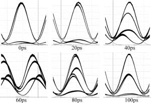
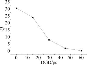
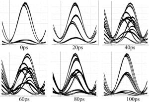
    图 3为接收端在不同DGD值下的眼图。图 4为不同DGD值对应的系统最大Q值曲线图。根据眼图可知,系统传输性能随着DGD值的增大不断变差。当DGD值为0ps时,眼图的眼开度很高,表示此时系统传输性能良好。当DGD值不断增大后,眼开度不断变小,说明PMD效应对PPM信号性能的影响越来越强。根据Q值曲线图,总体上看,系统最大Q值随着DGD值的增大而减小,且在DGD处于15ps至30ps间迅速下降;随后Q值减小的速度放缓,当DGD值为60ps时,系统最大Q值降为0,此时的系统传输性能已经很差了。

    Figure 3.  Eye diagram of different DGD at the rate of 10Gbit/s

    Figure 4.  Q vs. DGD at the rate of 10Gbit/s

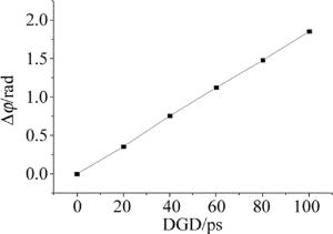
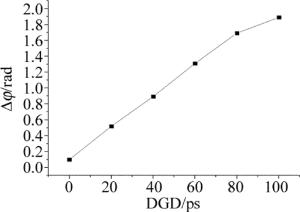
    图 5为不同DGD下F轴与S轴相位差Δφ绝对值的曲线。虽然相位差Δφ的符号反映的是F轴与S轴中哪个轴的信号滞后的情况,但在实际应用中,F轴和S轴是难以分辨的。因此选取PBS的一个输出轴作为参考,将其视作F轴,并以此计算相位差,取相位差Δφ的绝对值进行分析即可。前面对于PMD监测的原理分析提到了,Δφ与DGD线性相关。由图可知,Δφ的绝对值随着DGD的增大近似线性递增,与理论相符。这表明,本方案可以实现对0ps~100ps范围内PMD的监测。

    Figure 5.  Δφ vs.DGD at the rate of 10Gbit/s

  • 40Gbit/s速率下仿真实验系统的关键参量如下:连续光源的中心频率设定为193.1THz,线宽为10MHz,发射功率为3dBm;EDFA增益设置为20dB;可调谐滤波器的半波带宽为10GHz;本振射频信号频率为3GHz;低通滤波器3dB截止频率为10MHz;PMD模拟器加载的色度色散为10ps/nm,并分别加载不同的DGD。

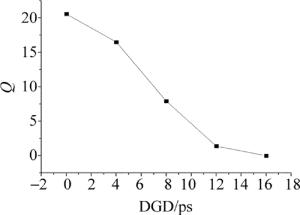
    图 6为接收端在不同DGD值下的眼图。图 7为不同DGD值对应的系统最大Q值曲线图。很明显,在相同DGD值下,40Gbit/s系统眼图的品质均不如10Gbit/s系统,这表明在速率更高的条件下,PPM信号传输性能更容易受色散的影响。由Q值曲线可知,40Gbit/s链路的系统最大Q值始终随DGD的增大快速下降。当DGD为16ps时,系统最大Q值已降为0。以上现象说明,40Gbit/s传输链路的性能劣化速度要远远大于10Gbit/s传输链路。这是因为随着传输速率的增大,系统的色散容限会相应减小。

    Figure 6.  Eye diagram of different DGD at the rate of 40Gbit/s

    Figure 7.  Q vs. DGD at the rate of 40Gbit/s

    图 8为不同DGD下F轴与S轴相位差Δφ绝对值的曲线。由图可知,Δφ的绝对值随着DGD的增大几乎线性增加,其线性程度依然保持得较好。这说明本方案受PPM传输速率影响较小,适用性广,可以实现不同传输速率系统的PMD在线监测。

    Figure 8.  Δφ vs. DGD at the rate of 40Gbit/s

3.   结论
  • 提出了针对PPM调制信号的偏振模色散监测方案,对其基本原理进行了分析,并进行了仿真验证与实验分析。该方案采用单边带频谱内两个偏置信号的位相差来测量光纤链路中的PMD,可以实现范围在0ps~ 100ps内的PMD监测。因为实际情况下,链路中的PMD不会无限累加,故本方案可以监测大部分情形下的PMD,而且其实现过程相对简单,无需加载额外信号,对器件性能要求较低,测量结果受信号速率影响较小,适应性好。本方案能实现针对PPM系统的实时动态监测。

Reference (16)

Catalog

    /

    DownLoad:  Full-Size Img  PowerPoint
    Return
    Return