Advanced Search

ISSN1001-3806 CN51-1125/TN Map

Volume 41 Issue 6
Sep.  2017
Article Contents
Turn off MathJax

Citation:

Numerical study on output characteristics of single-pulse mode-locked fiber lasers

  • Corresponding author: DING Yingchun, dingyc@mail.buct.edu.cn
  • Received Date: 2016-11-15
    Accepted Date: 2016-12-22
  • In order to analyze the output characteristics in single-pulse mode-locked fiber lasers with different net cavity dispersion, a numerical model based on the nonlinear Schr dinger equation is conducted to analyze the pulse evolution in the cavity by using the split-step Fourier method. According to the numerical simulation, the relationship between some parameters in fiber lasers and the net cavity dispersion is proven theoretically, and in the case that the net cavity dispersion is positive, the output pulse is compressed outside the cavity numerically and the compression ratio reaches up to ten times. Then the values of the required dispersion and the pulse width after compression are calculated. The results show that the maximum small-signal gain coefficient is proportional to the net cavity dispersion in general. And when the small-signal gain coefficient reaches the maximum value, the pulse width and the time-bandwidth product(TBP) increase gradually, and the 3dB bandwidth increases first and then decreases with the increase of the net cavity dispersion. The conclusion can provide reference for optimizing passively mode-locked fiber lasers.
  • 加载中
  • [1]

    FERMANN M E, HARTL I. Ultrafast fiber laser technology[J].IEEE Journal of Selected Topics in Quantum Electronics, 2009, 15(1):191-206. doi: 10.1109/JSTQE.2008.2010246
    [2]

    SIBBETT W, LAGATSKY A A, BROWN C T. The development and application of femtosecond laser systems[J]. Optics Express, 2012, 20(7):6989-7001. doi: 10.1364/OE.20.006989
    [3]

    KALISKY Y. Cr4+:YAG as passive Q-switch and Brewster plate in a pulsed Nd:YAG laser[J]. IEEE Journal of Quantum Electronics, 1995, 31(10):1738-1741. doi: 10.1109/3.466043
    [4]

    DEMARIA A J, STETSER D A, HEYNAU H. Self mode-locking of lasers with saturable absorbers [J]. Applied Physics Letters, 1966, 8(7):174-176. doi: 10.1063/1.1754541
    [5]

    ZHAO Y, LIU Y Zh, ZHAO D Sh, et al. Evolution of mode-locked technology of fiber lasers[J]. Laser Technology, 2009, 33(2):162-165(in Chinese).
    [6]

    CABASSE A, MARTEL G, OUDAR J L. High power dissipative soliton in an Erbium-doped fiber laser mode-locked with a high modulation depth saturable absorber mirror[J]. Optics Express, 2009, 17(12):9537-9542. doi: 10.1364/OE.17.009537
    [7]

    TANG D Y, ZHAO L M. Generation of 47fs pulses directly from an erbium-doped fiber laser[J]. Optics Letters, 2007, 32(1):41-43.
    [8]

    SAKAKIBARA Y, TATSUURA S, KATAURA H, et al. Near-infrared saturable absorption of single-wall carbon nanotubes prepared by laser ablation method[J]. Japanese Journal of Applied Physics, 2003, 42(5A):L494-L496.
    [9]

    SUN Z, HASAN T, TORRISI F, et al. Graphene mode-locked ultrafast laser[J]. ACS Nano, 2009, 4(2):803-810.
    [10]

    XIA H D, LI H P, WANG Z G, et al. Nanosecond pulse generation in a graphene mode-locked erbium-doped fiber laser[J]. Optics Communications, 2014, 330:147-150. doi: 10.1016/j.optcom.2014.05.048
    [11]

    WANG J, CAI Z, XU P, et al. Pulse dynamics in carbon nanotube mode-locked fiber lasers near zero cavity dispersion[J]. Optics Express, 2015, 23(8):9947-9958. doi: 10.1364/OE.23.009947
    [12]

    LU H T, WANG F, DENG T. Study of the self-similar evolution for optical pulse in nonlinearity-increasing fibers[J]. Laser Technology, 2010, 34(2):218-220(in Chinese).
    [13]

    JEON J, LEE J, JU H L. Numerical study on the minimum modulation depth of a saturable absorber for, stable fiber laser mode locking[J]. Journal of the Optical Society of America, 2015, B32(1):31-37.
    [14]

    AGRAWAL G P. Nonlinear fiber optics[M]. 3th ed. San Diego, California, USA: Academic Press, 2001:39-51.
    [15]

    WISE F W, CHONG A, RENNINGER W H. High-energy femtosecond fiber lasers based on pulse propagation at normal dispersion[J]. Laser & Photonics Reviews, 2008, 2(1/2):58-73.
  • 加载中
通讯作者: 陈斌, bchen63@163.com
  • 1. 

    沈阳化工大学材料科学与工程学院 沈阳 110142

  1. 本站搜索
  2. 百度学术搜索
  3. 万方数据库搜索
  4. CNKI搜索

Figures(7) / Tables(1)

Article views(9198) PDF downloads(218) Cited by()

Proportional views

Numerical study on output characteristics of single-pulse mode-locked fiber lasers

    Corresponding author: DING Yingchun, dingyc@mail.buct.edu.cn
  • Department of Physics, School of Science, Beijing University of Chemical Technology, Beijing 100029, China

Abstract: In order to analyze the output characteristics in single-pulse mode-locked fiber lasers with different net cavity dispersion, a numerical model based on the nonlinear Schr dinger equation is conducted to analyze the pulse evolution in the cavity by using the split-step Fourier method. According to the numerical simulation, the relationship between some parameters in fiber lasers and the net cavity dispersion is proven theoretically, and in the case that the net cavity dispersion is positive, the output pulse is compressed outside the cavity numerically and the compression ratio reaches up to ten times. Then the values of the required dispersion and the pulse width after compression are calculated. The results show that the maximum small-signal gain coefficient is proportional to the net cavity dispersion in general. And when the small-signal gain coefficient reaches the maximum value, the pulse width and the time-bandwidth product(TBP) increase gradually, and the 3dB bandwidth increases first and then decreases with the increase of the net cavity dispersion. The conclusion can provide reference for optimizing passively mode-locked fiber lasers.

引言
  • 近年来,超短脉冲在一些重要领域得到了广泛的应用和研究,如超快诊断、生物工程、超连续谱产生以及光学测量等[1-2]。为了获得超短脉冲,通常有调Q[3]和锁模[4]两种方法,相较于调Q技术,锁模技术能获得脉宽更窄、功率更高的超短脉冲。自20世纪60年代实现激光锁模以来,锁模光纤激光器得到了飞速的发展。现阶段的锁模技术通常分为主动锁模和被动锁模[5]。相较于主动锁模需要加入声光调制器或者电光调制器等复杂元件,被动锁模则具有良好的稳定性和简单性。被动锁模只需要在环形谐振腔加入具有等效可饱和吸收作用的器件就可以形成锁模,如半导体可饱和吸收镜[6](semiconductor saturable absorber mi-rror, SESAM)、非线性偏振旋转[7](nonlinear polarization rotation, NPR)、单壁碳纳米管[8](single-walled carbon nanotubes, SWCNTs)和石墨烯[9-10]等。

    在锁模光纤激光器中,腔内色散的控制是十分重要的因素[11]。通过控制腔内净色散的值可以使光纤激光器工作在不同的锁模区域。在净腔色散为负时,由于色散和非线性效应的作用,激光器工作在传统孤子锁模区域;而在净腔色散为正时,由于色散、非线性效应、增益和损耗的共同作用,激光器会工作在自相似脉冲或者耗散孤子锁模区域。当净腔色散不同时,脉冲能够承受的能量也不同,当脉冲能量过高时,脉冲就会不稳定进而发生分裂,由单脉冲转化为多孤子脉冲。

    为了避免光波分裂,使激光器保持单脉冲输出,本文中从脉冲在光纤中演化的实际出发,建立了同时包含色散、非线性效应、增益以及损耗的理论模型,分析了在不同净腔色散下,通过控制小信号增益系数来保证锁模激光器保持单脉冲输出,进而得到最大的小信号增益系数。在净腔色散为正时,由于脉冲具有较大的啁啾[12],对输出脉冲进行腔外压缩,分析计算了净腔色散对压缩所需色散以及压缩后脉宽的影响,具有实际的研究意义。

1.   理论模型
  • 基于可饱和吸收体的锁模光纤激光器的实验装置图如图 1所示。其中由一个976nm半导体激光器(laser diode,LD)作为抽运源,通过一个980nm/1550nm的波分复用器(wavelength division multiplexer, WDM)进入环形腔,环形腔中使用一段掺铒光纤(erbium-doped fiber, EDF)作为增益介质,而两段标准单模光纤(single-mode fiber, SMF)以及一段色散补偿光纤(dispersion compensating fiber, DCF)来控制环形腔内的色散,隔离器(isolator,ISO)和偏振控制器(polarization controller, PC)分别控制脉冲的传播方向和偏振方向,可饱和吸收体(saturable absorber,SA)是锁模激光器重要的锁模器件,最后激光器通过一个分光比为20/80的输出耦合器作为激光的输出。数值计算中的各项参量分别列在表 1中,表中SMF2控制腔内净色散,g0保证激光器单脉冲输出。

    Figure 1.  Schematic of mode-locked fiber laser

    fiber type β2/(ps2·km-1) γ/(W-1·km-1) L/m g0 /m
    EDF 38 5.3 4 variable
    SMF1 -22 1.1 4 0
    SMF2 -22 1.1 variable 0
    DCF 123 3.8 2 0

    Table 1.  Parameters of numerical simulation[10, 13]

    光脉冲在光纤中的演化过程可以用以下非线性薛定谔方程描述[14]

    式中,A(z, τ)是脉冲包络的慢变振幅,z是沿光纤的传输距离,τ是时间参量,β2γ分别为群速度色散参量和非线性系数,Ω为增益带宽,g为增益系数。在SMF和DCF中,g=0;在EDF中,g可以用以下公式表示:

    式中,g0为小信号增益系数,EEsat分别表示脉冲能量和增益饱和能量。这里忽略了光纤的损耗、高阶色散以及其它非线性效应。

    这个模型中的锁模器件是可饱和吸收体,它的非线性透过率可以表示为:

    式中,ΔT, PsPsat分别表示可饱和吸收体的调制深度、脉冲功率以及可饱和吸收体的饱和功率,α为可饱和吸收体的固有损耗。通过这个表达式可以发现,可饱和吸收体的透过率在脉冲功率高的部分透过率高,而在脉冲功率低的位置透过率低,如图 2所示[15]

    Figure 2.  a—transmission of saturable absorber b—effect of saturable absorber on pulse

    本次模拟中主要采用分步傅里叶的方法进行数值求解,将一个随机噪声信号作为模拟的初始信号,在谐振器内不断循环直至达到稳定的自洽状态。假定连续两次循环输出脉冲强度的相对误差不大于0.1%时,激光器达到稳定状态。模拟中采用的参量为:Esat=10pJ,ΔT=20%,Ω=40nm,Psat=72W,α=0.55,其余参量参照表 1

2.   数值模拟
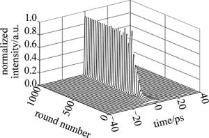
  • 锁模光纤激光器内脉冲的演化过程如图 3所示。一个随机噪声信号在腔内不断地自洽演化,循环1000圈后,得到稳定的锁模脉冲。

    Figure 3.  Evolution of output pulses in mode-locked fiber lasers

    通过调整SMF2的长度从27.5m到0.5m来控制腔内的净色散,使其在约-0.3ps2到约+0.3ps2的范围内变化。然后在每一个净腔色散下,改变小信号增益系数g0的值,使激光器保持在单脉冲锁模的状态,不断调整g0,得到激光器在保持单脉冲输出时g0的最大值,如图 4所示。从图中可以看出,在净腔色散为负时,激光器所承受的g0的最大值很小;而在净腔色散为正时,激光器所承受的g0相对较大。这是由于在负色散区,锁模激光器输出为传统孤子,能量很小;在正色散区,激光器输出为自相似脉冲,能量较高。

    Figure 4.  Maximum small-signal gain as a function of the net cavity dispersion

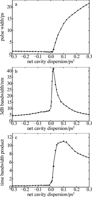
    图 5中给出了当g0取最大值时,不同净腔色散下输出脉冲的脉宽、3dB带宽以及相应的时间带宽积(time bandwidth product, TBP)的变化。图 5a中,脉宽在负色散区域变化较小,在正色散区域随腔内净色散的增加明显增大。从图 5b中可以看出,脉冲的3dB带宽随着腔内净色散的增加呈先增大后减小的趋势,并在零色散附近时达到最大值,这是由于在零色散附近,色散的影响相对较小,而非线性的影响相对较大。从图 5c中可以看出,时间带宽积在负色散区域非常小,接近转换极限;在正色散区域很大,存在很大的啁啾,可以进行腔外解啁啾压缩。

    Figure 5.  Parameter variation of output pulse with different net cavity dispersions

    在腔内净色散为正时,输出脉冲的频率啁啾信息如图 6a所示,此时脉冲具有较大的正啁啾,可以通过在腔外加一段负色散光纤来进行解啁啾压缩,压缩后的脉冲如图 6b所示,脉冲宽度由压缩前的5.15ps压缩到530fs。

    Figure 6.  Temporal shape and chirp information

    此外,进一步分析了压缩后脉冲宽度以及压缩所需色散值与腔内净色散的关系,如图 7所示。图 7a中展示了脉冲在压缩前后脉宽的对比,发现脉冲压缩后脉宽能降低10倍以下。由图 7b可以看出,随着净腔色散的增大,脉冲进行腔外压缩所需的负色散也越来越大,这是由于净腔色散增大,积累的啁啾也增大,进行脉冲压缩需要补偿的负色散量也随着增加。

    Figure 7.  a—pulse width before compression and after compression b—the required net dispersion outside the cavity with different net cavity dispersions

3.   结论
  • 通过数值计算分析了单脉冲锁模光纤激光器所能承受的小信号增益系数g0的最大值与腔内净色散的变化关系,这种变化主要是由于激光器在不同净腔色散下锁模区域不同、输出脉冲的承受能量不同导致的。同时,计算了当g0取最大值时,脉宽、3dB带宽以及TBP随腔内净色散的变化关系,发现在正色散区域,脉冲的TBP的数值很大,脉冲具有非常大的啁啾。通过对正色散区域的输出脉冲进行腔外压缩,得到压缩所需的色散值、压缩后的脉宽,压缩比达到10倍以上。

Reference (15)

Catalog

    /

    DownLoad:  Full-Size Img  PowerPoint
    Return
    Return