Advanced Search

ISSN1001-3806 CN51-1125/TN Map

Volume 41 Issue 6
Sep.  2017
Article Contents
Turn off MathJax

Citation:

Non-scanning active imaging lidar based on APD planar array detector

  • Received Date: 2016-12-22
    Accepted Date: 2017-01-12
  • In order to obtain high-precision 3-D range images of target regions, a non-scanning active imaging lidar was developed by using avalanche photodiode (APD) array detector assembly with readout circuit developed by ourselves. Pulse laser at wavelength of 1.064μm was used to irradiate target areas and an APD array detector module was used to receive target diffuse reflection laser echo signal. After information processing, the target area 3-D range images were obtained. The experiment study was carried out on typical targets 3-D imaging. The results show that, the developed non-scanning active imaging lidar can obtain good target area 3-D range images with imaging distance of 1.2km, range resolution of 0.45m and imaging frame rate of 20Hz. The technology of non-scanning active imaging lidar based on APD array detector has made a breakthrough.
  • 加载中
  • [1]

    CAI X P, YU Ch B, CHEN L, et al. State-of-the-art of three-dimensional imaging laser radar[J]. OME Research Forum, 2008, 25(7):31-35(in Chinese).
    [2]

    VAIDYANATHAN M, BLASK S, HIGGINS T, et al. Jigsaw phase Ⅲ:a miniaturized airborne 3-D imaging laser radar with photon-counting sensitivity for foliage penetration[J]. Proceedings of the SPIE, 2007, 6550:65500N. doi: 10.1117/12.722880
    [3]

    SUDHARSANAN R, YUAN P, BOISVERT J, et al. Single photon counting geiger mode ingaas(p)/inp avalanche photodiode arrays for 3-D Imaging[J]. Proceedings of the SPIE, 2008, 6950:69500N. doi: 10.1117/12.778278
    [4]

    GUO Y, HUANG G, SHU R. 3-D imaging laser radar using geiger-mode apds:analysis and experiments[J]. Proceedings of the SPIE, 2010, 7684:7684021.
    [5]

    YUAN P Sh, LIU Q. Non-scanning 3-D range-gated imaging lidar experiment system[J]. Journal of Atmospheric and Environmental Optics, 2008, 3(2):147-150(in Chinese).
    [6]

    LI S N, LIU Y, ZHANG F H, et al. Simulation research of laser three-dimensional imaging system based on range gated technology[J]. Chinese Journal of Lasers, 2009, 36(s2):331-334(in Chin-ese).
    [7]

    LIU Y. Experimental study based on the range-gated laser imaging[D]. Harbin: Harbin Institute of Technology, 2010: 45-47(in Chin-ese).
    [8]

    JIN C, ZHAO Y, ZHANG Y, et al. Scannerless Three-dimensional imaging using a pulsed laser and an intensified charge-coupled device with linearly modulated gain[J]. Applied Optics, 2009, 48(19):3823-3829. doi: 10.1364/AO.48.003823
    [9]

    WANG F, ZHAO Y, ZHANG Y, et al. Multi pulse gain-modulated three-dimensional imaging system[J]. Chinese Journal of Lasers, 2010, 37(9):1961-1966(in Chinese).
    [10]

    YAN H M, HU J, ZHANG X D, et al. The staring imaging laser radar based on plane array detector[J]. Opto-Electronic Engineering, 2013, 40(2):8-16(in Chinese).
    [11]

    LIU J B, LI S N, WANG Q, et al. System design and experiment of multiple streak tube imaging lidar[J]. Chinese Journal of Lasers, 2009, 36(9):1991-1994(in Chinese).
    [12]

    WEI J S, WANG Q, SUN J F, et al. High-resolution imaging of a long-distance target with a single-slit streak-tube lidar[J]. Journal of Russian Laser Research, 2010, 31(4):307-312(in Chinese). doi: 10.1007/s10946-010-9149-z
    [13]

    STANN B L, ALIBERTI K, CAROTHERS D, et al. A 32×32 pixel focal plane array ladar system using chirped amplitude modulation[J]. Proceedings of the SPIE, 2004, 5412:264-272. doi: 10.1117/12.542549
    [14]

    REDMAN B C, STANN B, LAWLER W, et al. Chirped AM ladar for anti-ship missile tracking and force protection 3-D imaging:update[J]. Proceeding of the SPIE, 2006, 6214:62140O. doi: 10.1117/12.666961
    [15]

    VERGHESE S, MCINTOSH K A, LIAU Z L, et al. Arrays of 128×32 InP-based geigermode avalanche photodiodes[J]. Proceedings of the SPIE, 2009, 7320:73200M. doi: 10.1117/12.821875
    [16]

    JACK M, CHAPMAN G, EDWARDS J, et al. Adances in LADAR Components and Subsystems at Raytheon[J]. Proceedings of the SPIE, 2012, 8353:8352F.
    [17]

    DAI Y J. Laser radar techniques[M]. Beijing:Publishing House of Electronics Industry, 2010:179-183(in Chinese).
  • 加载中
通讯作者: 陈斌, bchen63@163.com
  • 1. 

    沈阳化工大学材料科学与工程学院 沈阳 110142

  1. 本站搜索
  2. 百度学术搜索
  3. 万方数据库搜索
  4. CNKI搜索

Figures(8)

Article views(8503) PDF downloads(227) Cited by()

Proportional views

Non-scanning active imaging lidar based on APD planar array detector

  • Southwest Institute of Technical Physics, Chengdu 610041, China

Abstract: In order to obtain high-precision 3-D range images of target regions, a non-scanning active imaging lidar was developed by using avalanche photodiode (APD) array detector assembly with readout circuit developed by ourselves. Pulse laser at wavelength of 1.064μm was used to irradiate target areas and an APD array detector module was used to receive target diffuse reflection laser echo signal. After information processing, the target area 3-D range images were obtained. The experiment study was carried out on typical targets 3-D imaging. The results show that, the developed non-scanning active imaging lidar can obtain good target area 3-D range images with imaging distance of 1.2km, range resolution of 0.45m and imaging frame rate of 20Hz. The technology of non-scanning active imaging lidar based on APD array detector has made a breakthrough.

引言
  • 由于激光主动成像雷达可获得目标的距离图像,具有极强的目标分类识别能力,甚至可识别被部分遮挡或伪装目标,近年来该技术获得了长足的发展。早期的激光主动成像雷达通过机械扫描装置逐点扫描获取目标的3维(three dimensional, 3-D)信息,其优势是成像距离较远,对激光器输出功率要求不高,但系统大而笨重,存在成像速度慢,对运动目标易造成图像模糊等缺点。非扫描激光主动成像雷达采用面阵探测器接受目标反射激光回波信号,具有成像帧频高、对运动目标无图像模糊问题等特点。目前,非扫描激光主动成像探测技术主要有基于雪崩光电二极管(avalanche photodiode,APD)阵列3维成像技术[1-4]、距离选通3维成像技术[5-7]、增益调制3维成像技术[8-10]、基于条纹管的3维成像技术[11-12]和连续波3维成像技术[13-14]等几种方式。由于APD面阵灵敏度高(甚至能达到单光子量级),基于APD面阵探测器组件的非扫描激光主动成像雷达具有成像距离远、系统结构简单及易于小型化等特点,是当今激光主动成像雷达的热点发展方向之一。

    APD探测器分线性和盖革两种工作模式,即线性模式雪崩光电二极管探测器(line-mode avalanche photodiode, LM-APD)和盖革模式雪崩光电二极管探测器(Geiger-mode avalanche photodiode, GM-APD)。目前,国外GM-APD阵列器件规模已达256×32[15]和256×64,甚至计划开展1024×1024器件的研制,且已有单光子LM-APD阵列器件的研究报道[16]

    本文中基于自研带读出电路LM-APD面阵探测器组件构建非扫描激光成像雷达系统,成像距离达1.2km,成像实验表明,一个脉冲照明即可获得目标一帧3维距离图像,国内在基于APD面阵探测器组件的非扫描激光主动成像雷达技术取得了关键性突破。

1.   激光成像雷达系统设计
  • 激光主动成像雷达组成原理框图如图 1所示。它由收发(transmit/receive,T/R)光学系统、全固态激光器、激光电源、带读出电路LM-APD面阵探测器组件、信息处理板、系统控制板和图像显示器等构成。全固态激光器在系统控制板触发信号作用下,发射激光脉冲泛光照明目标场景区域,目标漫反射的激光信号经接收光学系统会聚于APD面阵探测器组件的光敏面上,经光电转换后触发时间间隔测量电路,记录回波到达时间,在系统控制板的控制下,有序读出APD面阵探测器各像元中的激光脉冲飞行时间信息,经信息处理及图像重构获得3维距离图像,图像送显示器显示。

    Figure 1.  Principle diagram of active imaging lidar

    根据雷达方程,探测器单像元所接收到的激光回波功率Pd可由下式给出[17]

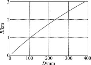
    式中, P0为发射激光峰值功率;θ为激光束照射角;θd为单像元接收视场角;D为接收光学系统直径;R为成像距离;ρ为目标激光满反射率;α为大气衰减系数;τt为发射光学系统透过率;τ0为窄带虑光片透过率;τr为接收光学系统透过率。给定RD和面阵探测器像元的最小可探测功率Pmin(即探测灵敏度)值,从(1)式(令Pd=Pmin)则可推得达成像距离R所需的激光照射峰值功率。从(1)式可知,增大接收光学系统口径D,可有效增加雷达的成像距离,其它参量恒定条件下成像距离RD的变化曲线如图 2所示。可见,R较小时,约为线性关系。

    Figure 2.  Relationship between R & D

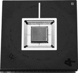
  • 带读出电路LM-APD面阵探测器组件工作于线性模式,由InGaAs雪崩光电二极管面阵芯片和时间计数型CMOS读出电路芯片(readout-integrated circuit, ROIC)构成,APD面阵芯片采用InGaAs外延材料通过扩散方式制作,ROIC采用硅CMOS专用集成电路,主要由前放电路、主放大器、比较器、高精度计时电路等模块构成,通过In柱阵列与APD面阵芯片倒装互联形成探测器组件。图 3为APD面阵探测器组件。系统工作时,通过外控触发信号,启动ROIC内部计数器开始计数,当激光回波被探测到后,电路产生stop终止信号停止计数,有序读出计数器的值即为激光脉冲往返飞行时间值,实现像元级独立距离测量功能。多行信号并行读出,每一列信号串行读出。主要技术指标为:(1)工作波长1.064μm;(2)像元数32×32;(3)像元直径Ø50μm;(4)像元间距150μm;(5)最小可探测功率400nW;(6)时间分辨率1ns。

    Figure 3.  Assembly of APD planar array detector

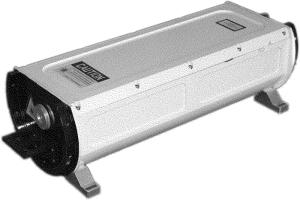
  • 全固态激光照射器是激光主动成像雷达的关键模块之一,因激光成像雷达要求具有较高的距离分辨率(小于0.5m),而带读出电路面阵探测器组件的集成测距定时电路较简单,要实现较高的距离分辨率,则要求照射激光脉冲的脉冲宽度较窄,通常小于3ns。全固态激光照射器采用高增益LD抽运Nd:YAG模块+快速电光Q开关技术获得高功率窄脉冲激光输出。窄脉冲全固体激光器如图 4所示。其主要技术指标为:(1)工作波长1.064μm;(2)脉冲宽度2ns;(3)单脉冲能量40mJ;(4)重复频率20Hz。

    Figure 4.  All-solid-state laser with narrow pulse-width

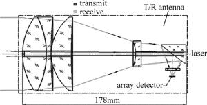
  • 为了尽量减小激光成像雷达体积、重量,激光收发光学系统采用共轴一体化设计,并采用摄远光学系统技术进一步缩小光学系统的长度,光学系统原理框图如图 5所示。激光脉冲经光学系统中心光轴孔发射,目标回波信号经接收物镜组、摄远负透镜、折反棱镜会聚于面阵探测器光敏面上。探测器附近的激光发射通道采取屏蔽隔离措施有效降低激光发射对面阵探测器的干扰。

    Figure 5.  optical receiving and transmitting system with coaxial integrated design

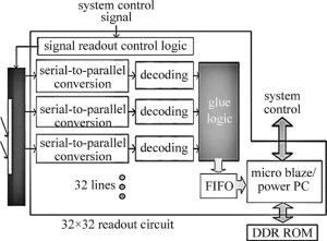
  • 采用FPGA技术实现雷达信息的高速读出和处理,在系统控制信号作用下,按照既定的时序关系,有序读出面阵探测器组件各像元的激光脉冲飞行时间信息值,32行信息并行读出,每一列的信息串行读出。由于面阵探测器组件采用线性反馈移位寄存器实现时间数字转换(time digtal convert, TDC),读出的信息值先进行译码转换为线性编码,并进行数据重排,送后续电路处理。因每像素数据为13bit,读出时钟为10MHz,则每帧读出时间约42s,读出速率可以达到2.3×10⁴frame/s。信号读出的硬件框图如图 6所示。

    Figure 6.  Diagram of detector signal readout hardware

    将原始数据转换成3-D输出。首先,将单脉冲角度-角度-距离图像转换至笛卡尔坐标系,坐标转换时,每像素对应的激光脚点在本地坐标系中可表示如下:

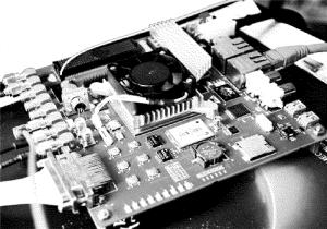
    式中, (xi, j, k, yi, j, k, zi, j, k)T表示第k个搜索视场中,探测器上第i行、第j列对应像素测定距离ri, j, k对应激光脚点的坐标转换值, T表示转置;αj表示探测器上第j列对应的瞬时方位角,βi表示探测器上第i行对应的瞬时俯仰角,δk为第k次搜索瞬时视场中心对应的方位角。坐标定义为:激光脚点在以观察点为原点,以搜索视场中心激光发射指向为z坐标, 与之垂直为x-O-y平面,设探测器行列方向分别与x轴和y轴平行,搜索平台转轴平行y轴。其次,把成像场景对应的3维空间按照相应的分辨率划分成一个个的小体积元,然后将x-y-z坐标点放置到对应的体积元中,从而将连续坐标转换为离散坐标。再其次,通过预处理滤波,可移除噪声点从而改善图像质量。对面阵探测器中的坏点,通过双线性内插来完成哑元补偿。最后,利用OpenGL双缓存技术实现点云图像的实时显示,可通过距离深度RGB颜色编码,突出显示效果。图 7是雷达信息处理板。

    Figure 7.  Board of lidar signal processing

2.   成像实验及结果
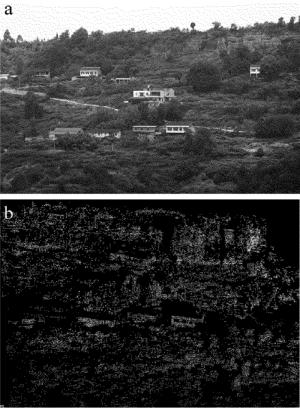
  • 根据激光主动成像雷达组成原理框图(见图 1),采用自研的带读出电路LM-APD面阵探测器组件,集成了一台非扫描激光主动成像雷达原理装置,雷达最大照射激光脉冲能量约为40mJ,照射激光重复频率为20Hz,接收光学系统有效孔径Ø140mm。目标成像验证实验表明,一个激光脉冲即可获得一帧稳定的3-D距离图像,激光雷达成像帧频达20Hz,其成像距离约为1.2km。图 8为成都市某地楼房群照片和雷达对其所成的3-D距离图像。距离分辨率实验(错位前后放置木板作为模拟目标)表明, 激光成像雷达可分辨的最小木板间距为0.45m,即雷达的距离分辨率为0.45m。

    Figure 8.  The photo of target area and 3-D cloud point range image of lidar

3.   结论
  • 采用1.064μm脉冲激光泛光照明,自研带读出电路APD面阵探测器组件接收,研制了一台非扫描激光主动成像雷达系统,开展了目标3-D成像实验研究。大量的成像实验显示,激光成像雷达可获得较好的目标3维距离图像,表明国内在带读出电路LM-APD面阵探测器组件技术和基于APD面阵探测器组件的非扫描激光主动成像雷达技术等领域取得了关键性突破。下一步拟在典型目标3-D图像特征提取、目标设别和典型目标3-D图像特征库建立等方面开展研究工作,并优化APD面阵探测器组件性能,拟在提高探测灵敏度、提高填充率、缩小组件尺寸和降低单元间光电子串扰等方面进一步开展研究工作。

Reference (17)

Catalog

    /

    DownLoad:  Full-Size Img  PowerPoint
    Return
    Return