-
激光熔覆是一种在基体材料表面通过激光技术熔上一种特殊涂层的技术[1]。涂上涂层的基体能够大大地改善基体材料的表面性能,提高设备的使用寿命[2]。为了提高熔覆材料与基体的结合力,需对激光熔池的温度进行检测。激光熔池的温度检测方法分为接触式和非接触式两种[3]。接触式测量一般采用热电偶测量方法,该方法不能对熔池温度进行直接测量,测量结果不能直接用于系统反馈[4]。非接触式测量主要包括单色或双色高温计[5]和CCD工业相机测量方法[3]。利用CCD与图像处理的方法应用较广,该方法具有成本低、操作简单、检测速度快等特点[6],但利用CCD采集得到的图像数据噪声较多,容易产生较大的系统误差,数据处理也较为复杂。现阶段利用CCD与图像处理结合测量熔池温度的方法已经进行了部分研究,但大都处于实验室研究阶段[3]。
本文中采用OpenCV和VS2013搭建了温度检测系统[7],利用CCD与图像处理相结合的方法检测熔池温度场的温度,采用中值滤波方法去除图像噪声,结合黑体辐射公式计算激光熔池温度。该检测系统在工业现场实现了实际的应用,对粉末材料、送粉速率等参量选择有一定的反馈和指导作用。
-
黑体的光谱辐射强度与其波长和温度有关[8]。物体的光谱辐射通量密度与温度、波长的数学公式与黑体的类似[9]。由普朗克定律得知,黑体的热辐射通量密度Db(λ, T)与辐射物体的温度T、辐射波长λ的数学关系式如下:
${D_{\rm{b}}}\left( {\mathit{\lambda , T}} \right) = \mathit{\varepsilon }\left( {\mathit{\lambda , T}} \right)\frac{{{N_1}}}{{{\mathit{\lambda }^5}}}\exp \left( { - \frac{{{N_2}}}{{\lambda T}}} \right) $
(1) 式中, N1,N2为辐射常数,ε(λ, T)是辐射率。
由两个不同波长黑体的热辐射通量密度之比即可得到测量物体的温度[9]:
$T = \frac{{{N_2}\left( {\frac{1}{{{\mathit{\lambda }_2}}} - \frac{1}{{{\mathit{\lambda }_1}}}} \right)}}{{\ln \left[ {\frac{{{D_{\rm{b}}}\left( {{\mathit{\lambda }_1}, T} \right)}}{{{D_{\rm{b}}}\left( {{\mathit{\lambda }_2}, T} \right)}}} \right] - LN\left[ {\frac{{\mathit{\varepsilon }\left( {{\mathit{\lambda }_1}, T} \right)}}{{\varepsilon \left( {{\mathit{\lambda }_2}, T} \right)}}} \right]5\ln \left( {\frac{{{\mathit{\lambda }_{\rm{2}}}}}{{{\mathit{\lambda }_1}}}} \right)}} $
(2) 被测对象为金属高温激光熔池,不同波长λ1和λ2对应的辐射率ε(λ1, T)与ε(λ2, T)近似相等[8],故公式可简化为:
$\begin{array}{l} T = - \\ \frac{{{N_2}\left( {\frac{1}{{{\mathit{\lambda }_{\rm{1}}}}} - \frac{1}{{{\mathit{\lambda }_2}}}} \right)}}{{\ln \left[ {{R_{12}}\left( T \right)} \right] - LN\left[ {\frac{{C\left( {{\mathit{\lambda }_1}, T} \right)\mathit{\eta }\left( {{\mathit{\lambda }_1}, T} \right){{\left( {{m_1}\mathit{'}{\mathit{n}_{\rm{2}}}} \right)}^2}{K_{\rm{1}}}\mathit{\delta }{\mathit{\lambda }_{\rm{1}}}}}{{C\left( {{\mathit{\lambda }_2}, T} \right)\mathit{\eta }\left( {{n_2}, T} \right){{\left( {{n_{\rm{2}}}\mathit{'}{\mathit{n}_{\rm{1}}}} \right)}^2}{K_{\rm{2}}}\mathit{\delta }{\mathit{\lambda }_{\rm{2}}}}}} \right] - 5LN\left( {\frac{{{\mathit{\lambda }_{\rm{2}}}}}{{{\mathit{\lambda }_1}}}} \right)}} \end{array} $
(3) 式中,C(λ, T)为灰度转换系数,n1和n1′为波长λ1对应的物方和像方介质折射率,n2和n2′为波长λ2对应的物方和像方介质折射率,K1和K2表示波长λ1和波长λ2对应的系统透过率,η(λ, T)为彩色CCD相机的光谱响应系数,δ为彩色CCD各像素点滤光片响应带宽。其中λ1和λ2为已知波长,R12为λ1和λ2对应图像的像素值比值,$\ln \left[ {\frac{{C\left( {{\mathit{\lambda }_{\rm{1}}}, T} \right)\mathit{\eta }\left( {{\mathit{\lambda }_1}, T} \right){{\left( {{\mathit{n}_{\rm{1}}}\mathit{'}{\mathit{n}_{\rm{2}}}} \right)}^2}{K_1}\mathit{\delta }{\mathit{\lambda }_1}}}{{C\left( {{\mathit{\lambda }_2}, T} \right)\mathit{\eta }\left( {{\mathit{\lambda }_2}, T} \right){{\left( {{\mathit{n}_2}\mathit{'}{\mathit{n}_1}} \right)}^2}{K_2}\mathit{\delta }{\mathit{\lambda }_2}}}} \right]$为定值,可通过黑体炉的标定实验得出。
彩色CCD相机拍摄得到的真彩色图像包含λR,λG,λB3个通道的波长值及对应通道的像素值。由双比色原理可知,选取两个不同波长黑体的热辐射通量密度之比即可得到测量物体的温度,故选择彩色图像中两个通道的数据信息进行比较,可推算得到激光熔池的温度[8]。红光R通道的波长为700nm,绿光G通道的波长为546nm,蓝光B通道的波长为436nm[8]。
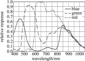
本文中采用DALSA-C2050彩色CCD工业相机拍摄数据,相机帧率为38,满足数据采集的速度需求。相机波长与相对响应系统关系如图 1所示。相机的采集波段为400nm~1000nm,满足检测436nm~700nm的实际需求,并且相机在要求波长的相对系数较高,得到的图像质量效果较好。此型号工业相机的重复精度很高,误差可以忽略。
在波长相近时,激光熔池的辐射率也大致相同,两个波长对应的方介质折射率与光谱相应系数比值近似为1[8]。由(3)式可知,选取波长相近的通道数据可减少计算量。由比较得知,|λR-λB|>|λR-λG|>|λG-λB|,故CCD彩色相机的G通道波长和B通道波长最相近,因此选择这两个波段相关数据代入(3)式计算熔池温度。
-
由于现场环境、拍摄角度、周围环境光等方面的影响,由彩色CCD相机拍摄得到的图像含有较多的噪声,对处理结果产生较大的影响。为了提高测量的精度,需要对原始采集图像进行预处理操作[10-12]。
中值滤波能够有效去除图像的噪声、提高采集图像的质量,方便后续的图像处理。中值滤波的原理为将图像中某一个像素点值用其邻域各个点值经过排序后的中值代替[13]。中值滤波的数学定义为:图像数据点为x1, x2, x2, …, xm(m为自然数),将此部分数据从小到大排列,得到X1, X2, X2, …, Xm。设y为此邻域点的中值,计算公式如下:
$y = \left\{ \begin{array}{l} {X_\mathit{i}}\left( {\frac{{m + 1}}{2}} \right), \left( {m{\rm{\;is\;an\;odd\;number}}} \right)\\ \frac{{{X_\mathit{i}}\left( {\frac{m}{2}} \right) + {X_\mathit{i}}\left( {\frac{{m + 2}}{2}} \right)}}{2}, \left( {\mathit{m}\;{\rm{is\;an\;even\;number}}} \right) \end{array} \right. $
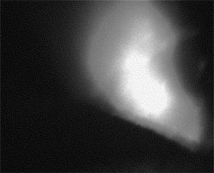
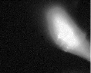
(4) 把图像中某个像素点的固定形状或长度作为窗口,窗口中的像素值用窗口内邻域点的中值代替。本文中以现场拍摄的熔池为例,熔池的温度大约在2250℃,将图像经中值滤波后,原图与滤波后的效果图对比如图 2和图 3所示。
由图 2与图 3分析比较可知,图像经中值滤波可消除或者减弱在激光熔覆过程中由于粉末迸溅造成的影响,提高了图像质量,为后续图像处理奠定了良好的基础。
-
温度检测系统标定的原理为将黑体炉[14-15]辐射出的辐射能,利用彩色CCD工业相机、滤光片组成的硬件系统采集图像数据,原始图像数据经滤波去噪后,通过双比色原理比值测温法得到不同数据图像对应的温度值。
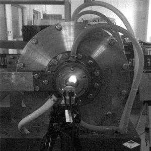
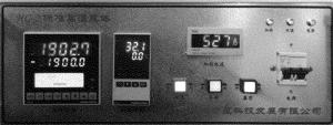
本文中利用高精度HG-2标准高温黑体炉用于检测系统的温度标定,此型号的温度范围为0℃~3000℃。搭建的硬件系统如图 4所示。设定标准温度值后黑体炉可达到设定温度并一直保持,通过搭建的硬件测温系统获取数据图像。通过黑体炉显示器设定需达到的温度及监测黑体炉中实际的温度、电流等数值,黑体炉显示器如图 5所示。
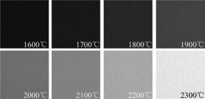
根据现场实际需求,熔池的温度大约在1800℃~2300℃之间,根据此需求,标定的数据范围在1600℃~2300℃。标定数据从1600℃开始,每隔100℃记录一次数据,即用CCD相机拍摄图像数据,并将数据通过计算机存储于硬盘指定位置。拍摄得到的图像如图 6所示。
由彩色CCD拍摄得到的标定图片可知,图像的亮度随温度的升高变亮,图像的R通道、G通道、B通道的数值随着温度的升高变化明显。图像的R通道、G通道、B通道的数值分别为R, G, B。由前面测温原理推导公式可知,只需提取图像中某像素点的绿色和蓝色通道的像素数进行比值温度计算。提取1600℃~2300℃对应图像数据中的G和B值作为数据源。由于拍摄相同温度区域,理论上得到的整幅温度图像中各个像素点对应的像素数值完全相同,为消除系统误差,任取图像中的相同温度区域的5个数据点,取平均值,得到的G, B数据见表 1。为方便后续的公式拟合,G, B数据值后对应公式所需计算值,数值取小数点后4位。
Table 1. The extracted image data and the corresponding calculation value
G B G/B ln(G/B) T/℃ 24 19 1.2632 0.2336 1600 31 22 1.4091 0.3429 1700 43 27 1.5926 0.4654 1800 62 34 1.8235 0.6008 1900 89 44 2.0227 0.7044 2000 119 56 2.1250 0.7538 2100 173 78 2.2179 0.7966 2200 241 108 2.2315 0.8027 2300 为便于通过彩色CCD相机采集得到的彩色数据快速得到熔池温度,需将表 1中的数据通过MATLAB采用最小二乘法对实验数据进行曲线拟合,得到温度T与比色值R12(${R_{12}} = \frac{G}{B} $, B和G分别表示G, B通道数据)的关系如下:
$\begin{array}{l} T = \\ \frac{{182.4576}}{{ - \ln {R_{12}} - 0.1736{R_{12}}^2 + 1.1595{R_{{\rm{12}}}} - 0.8396}} \end{array} $
(5) 表 1中的G, B通道数据为标准温度下对应的像素值,为验证公式的正确性,将表 1中的G, B通道像素值通过(5)式计算得到黑体炉内温度,将此数据与黑体炉实际标准温度对比,得到的结果如表 2所示。
Table 2. The fitting formula calculation value and the fitting point temperature error
G B calculated
temperature/℃actual
temperature/℃error/
℃resolution/
%24 19 1594.6 1600 5.4 0.34 31 22 1711.5 1700 11.5 0.68 43 27 1800.5 1800 0.5 0 62 34 1886.0 1900 14 0.74 89 44 2004.3 2000 4.3 0.22 119 56 2105.6 2100 5.6 0.27 173 78 2237.6 2200 37.6 1.71 241 108 2261.1 2300 38.9 1.70 数据标定的准确性是利用比色测温方法测量熔池温度的关键环节之一,由表 2中的计算结果可知, 拟合公式数据点的最大误差为1.71%,拟合公式满足精度需求。
-
通过现场实验发现,通过拟合公式计算得到的黑体炉温度与黑体炉显示器显示温度的数值及变化规律类似。为验证拟合公式的准确性,设置黑体炉固定温度,拍摄黑体炉内颜色图像,提取图像中的G, B通道数据,通过拟合公式计算图像数据对应温度,并将计算出的温度与设定的实际温度对比,数据的结果如表 3所示。
Table 3. The error between the fitting formula calculation value and the actual temperature
G B calculated
temperature/℃actual
temperature/℃error/
℃resolution/
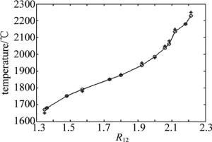
%27 20 1670.3 1650 20.3 1.23 30 22 1680.5 1680 0.5 0 37 25 1751.6 1750 1.6 0.91 44 28 1792.3 1780 12.3 0.69 52 30 1850.8 1850 0.8 0 63 35 1876.2 1880 3.8 0.20 75 39 1935.5 1950 14.5 0.74 90 45 1986.4 1980 6.4 0.32 103 50 2036.9 2050 13.1 0.64 123 59 2061.2 2080 18.8 0.90 142 67 2135.8 2150 14.2 0.66 192 88 2180.8 2180 0.8 0 208 94 2229 2250 21 0.93 将计算所得数据用MATLAB表示,效果图如图 7所示。其中横坐标为图像G通道与B通道像素值比值,纵坐标为黑体炉内温度,○点为拟合数据点,黑色线为拟合公式曲线,★点为实验数据点。
分析表 3及图 7得知,实验数据★点与其对应计算温度在拟合曲线附近,两通道比值及对应温度呈拟合公式规律变化。实验图像数据通过拟合公式计算得出的温度值与实际值最大误差为1.23%,满足现场测温要求。
-
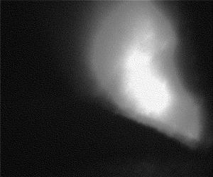
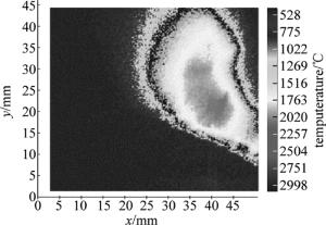
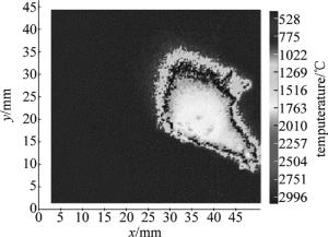
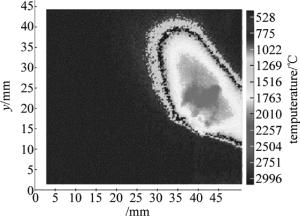
为形象描述熔池各个部分的温度,直观了解熔池各个区域的温度分布规律及变化趋势,需将滤波后的图像变换为伪彩色图像。伪彩色图像的定义为将熔池不同温度区域对应颜色变化差异明显图像[16-20]。通过彩色相机获取熔池数据后,将计算得到的温度转化为伪彩色图像。熔池彩色图像及对应计算得到的伪彩色图像效果如图 8和图 9所示。
图 9中右侧为标准颜色对准图,不同的温度对应着已定义的颜色。提取滤波后的图像中每一个像素点的R, G, B值,由(5)式计算得到图像每点对应的熔池点温度,由熔池温度推算得到图像伪彩色图。图 9中横纵坐标值能够反映出熔池的面积。由图 8与图 9对比可知,图 9能将温度明显区分,温度对比更加明显。
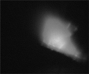
为验证系统的重复性及稳定性,通过多次实验进行数据分析,实验结果如图 10~图 13所示。
通过实验结果得知,该系统能够较准确地测量激光熔池的温度,系统的重复性及稳定性较好,实现了系统对熔池的温度检测。
-
本文中采用彩色CCD工业相机采集熔池数据图片,由于现场环境因素的影响,采用中值滤波的方法去除图像噪声,有效地提高了计算温度的精度。标定得到的图像数据采用MATLAB最小二乘法拟合得到温度计算公式。实验结果表明:通过拟合公式计算得到的黑体炉温度与黑体炉内实际温度变化规律类似;经实验数据分析比较,拟合公式满足现场测温的精度要求;将采集得到的图像经变换后得到伪彩色图像,伪彩色图像能够反映出各个区域的温度分布规律及变化趋势,增强了图像显示效果。通过图像处理技术实现了对激光熔池温度的检测。
图像处理技术在激光熔池温度检测的应用
Application of image processing technology in temperature measurement of laser pool
-
摘要: 为了提高材料的熔覆层性能,采用图像处理技术对激光熔池温度场进行了检测。利用彩色CCD工业相机采集图像数据,运用中值滤波方法去除图像噪声;处理后的图像数据经过高精度HG-2标准高温黑体炉标定后得到温度拟合公式。通过图像处理将原始图像转化为伪彩色图像,能够较好地反映熔池各个区域的温度分布及变化规律。结果表明,通过拟合公式计算得到的温度与实际温度最大误差为1.23%。检测精度满足现场需求,实现了对熔池的温度检测。Abstract: In order to improve the performance of cladding layer, image processing technology was used to detect the temperature field of laser molten pool. A color CCD industrial camera was used to collect the image data and median filtering method was used to remove the image noise. After processing, the image data were calibrated by high-precision HG-2 standard high temperature blackbody furnace, and temperature fitting formula was obtained. The original images were transformed into pseudo color images by image processing, which reflected temperature distribution and change rule in each area of the molten pool. The results show that the maximum error between the temperature calculated by the fitting formula and the actual temperature is 1.23%. The detection precision meets the demand of the field application, and temperature detection of molten pool is realized.
-
Key words:
- image processing /
- laser pool /
- pseudo color image /
- temperature detection
-
Table 1. The extracted image data and the corresponding calculation value
G B G/B ln(G/B) T/℃ 24 19 1.2632 0.2336 1600 31 22 1.4091 0.3429 1700 43 27 1.5926 0.4654 1800 62 34 1.8235 0.6008 1900 89 44 2.0227 0.7044 2000 119 56 2.1250 0.7538 2100 173 78 2.2179 0.7966 2200 241 108 2.2315 0.8027 2300 Table 2. The fitting formula calculation value and the fitting point temperature error
G B calculated
temperature/℃actual
temperature/℃error/
℃resolution/
%24 19 1594.6 1600 5.4 0.34 31 22 1711.5 1700 11.5 0.68 43 27 1800.5 1800 0.5 0 62 34 1886.0 1900 14 0.74 89 44 2004.3 2000 4.3 0.22 119 56 2105.6 2100 5.6 0.27 173 78 2237.6 2200 37.6 1.71 241 108 2261.1 2300 38.9 1.70 Table 3. The error between the fitting formula calculation value and the actual temperature
G B calculated
temperature/℃actual
temperature/℃error/
℃resolution/
%27 20 1670.3 1650 20.3 1.23 30 22 1680.5 1680 0.5 0 37 25 1751.6 1750 1.6 0.91 44 28 1792.3 1780 12.3 0.69 52 30 1850.8 1850 0.8 0 63 35 1876.2 1880 3.8 0.20 75 39 1935.5 1950 14.5 0.74 90 45 1986.4 1980 6.4 0.32 103 50 2036.9 2050 13.1 0.64 123 59 2061.2 2080 18.8 0.90 142 67 2135.8 2150 14.2 0.66 192 88 2180.8 2180 0.8 0 208 94 2229 2250 21 0.93 -
-


 网站地图
网站地图

 下载:
下载:
